MECHANIS V220-S Owner's manual

Mando de control mecánico tira-empuja.
Mechanical push-pull remote control.
V220-S V221-S
W220-S W221-S
Copyright © 2022 Mechanis S.L.
202203
Intrucciones de instalación y operación
Installation and operation instructions
Español 2
English 4
Mechanis

2
1. Introducción
Los mandos V220 Mechanis ofrecen control sobre
el inversor y la aceleración del motor, por medio
de dos palancas independientes. Pueden ser uli-
zados con diferentes cables ra-empuja pero por
los mandos están congurados de serie para ca-
bles universales 33C.
2. Caracteríscas principales
El mecanismo es apto para la operación directa de:
Aceleración tanto empujando como rando.
Inversor (cambio de marcha) tanto empujan-
do como rando.
Consulte el manual del fabricante del motor en
caso de duda.
3. Conexión de los cables.
Coloque el bulón roscado en el extremo del
cable a media carrera de la rosca.
Fije el cable al mando ulizando las abraza-
deras correspondientes suministradas con el
mando.
¡Atención!
Conecte siempre en primer lugar los cables al
mando. La conexión de los cables a los disposi-
vos sólo debe realizarse cuando el mando está
completamente instalado y se ha vericado el
correcto movimiento de los cables.
Coloque el bulón en el la posición de recorrido
deseado según la sección 6 de este manual.
Ponga el pasador del bulón.
Compruebe el recorrido y el correcto funcio-
namiento operando la palanca y ajústelo si es
necesario.
Asegúrese de que los terminales del cable
llegan rectos a los puntos de trabajo y no
existen curvas o tensiones.
Ulice suciente longitud de cable y evite
curvas pronunciadas.
Siga las instrucciones de instalación del fabri-
cante del cable para asegurarse un correcto
rendimiento del cable.
Conecte los terminales del cable a los disposi-
vos de acción del motor/disposivo.
4. Instalación.
Al elegir el lugar donde se vaya a realizar a instala-
ción, tenga en cuenta el ángulo máximo que puede
hacer la palanca y la longitud del mecanismo. Com-
pruebe que no existen elementos interiores o exte-
riores que puedan impedir el correcto funciona-
miento del mecanismo. Véase dimensiones princi-
pales al nal de este manual.
¡Antes de arrancar!
Verique la correcta operación del mando, con
el motor/disposivo parado, comprobando que
no hay resistencias ni funcionamientos inco-
ATENCIÓN: Las siguientes instrucciones conenen información de seguridad importante y deben ser
entregadas al propietario nal de la embarcación.
INFORMACION DE SEGURIDAD :
Lea estas instrucciones con detenimiento antes de la instalación.
El uso incorrecto o una instalación incorrecta puede resultar en la pérdida del control sobre el
propulsor con potenciales daños a cosas o personas.
Mechanis S.L. no acepta responsabilidades sobre instalaciones donde no se ulicen mecanismos o
instrumentos Mechanis S.L.
Mechanis S.L. no acepta responsabilidades sobre mecanismos que hayan sido manipulados o modi-
cados parcial o totalmente sin el consenmiento expreso de Mechanis S.L.
¡Atención!
Asegurese que selecciona el agujero correcto
según las caracteríscas del cable. Una selec-
ción incorrecta puede dañar el cable y/o el
mando.

3
V220S & V221S
Una vez seleccionado el lugar adecuado para la instalación realice el vaciado ulizando las planllas
de recorte incluidas.
En el vaciado resultante coloque el mando sin la tapa y céntrelo correctamente. Antes de marcar
los agujeros de jación compruebe colocando la tapa que la disposición es la correcta y el mando queda
bien centrado y el vaciado completamente tapado.
Marque los agujeros de jación y rere el mando para taladrar.
Taladre los agujeros con una broca de 6 mm.
Limpie la zona y je el mando con tornillos M6 de longitud adecuada a la consola.
Siga los pasos indicados en “3. Conexión de los cables”.
Ajustar la fricción de la palanca según “7. Ajuste de fricción”.
Engrase la transmisión si es necesario.
Coloque la tapa protectora y jela a la base mediante los tornillos suministrados.
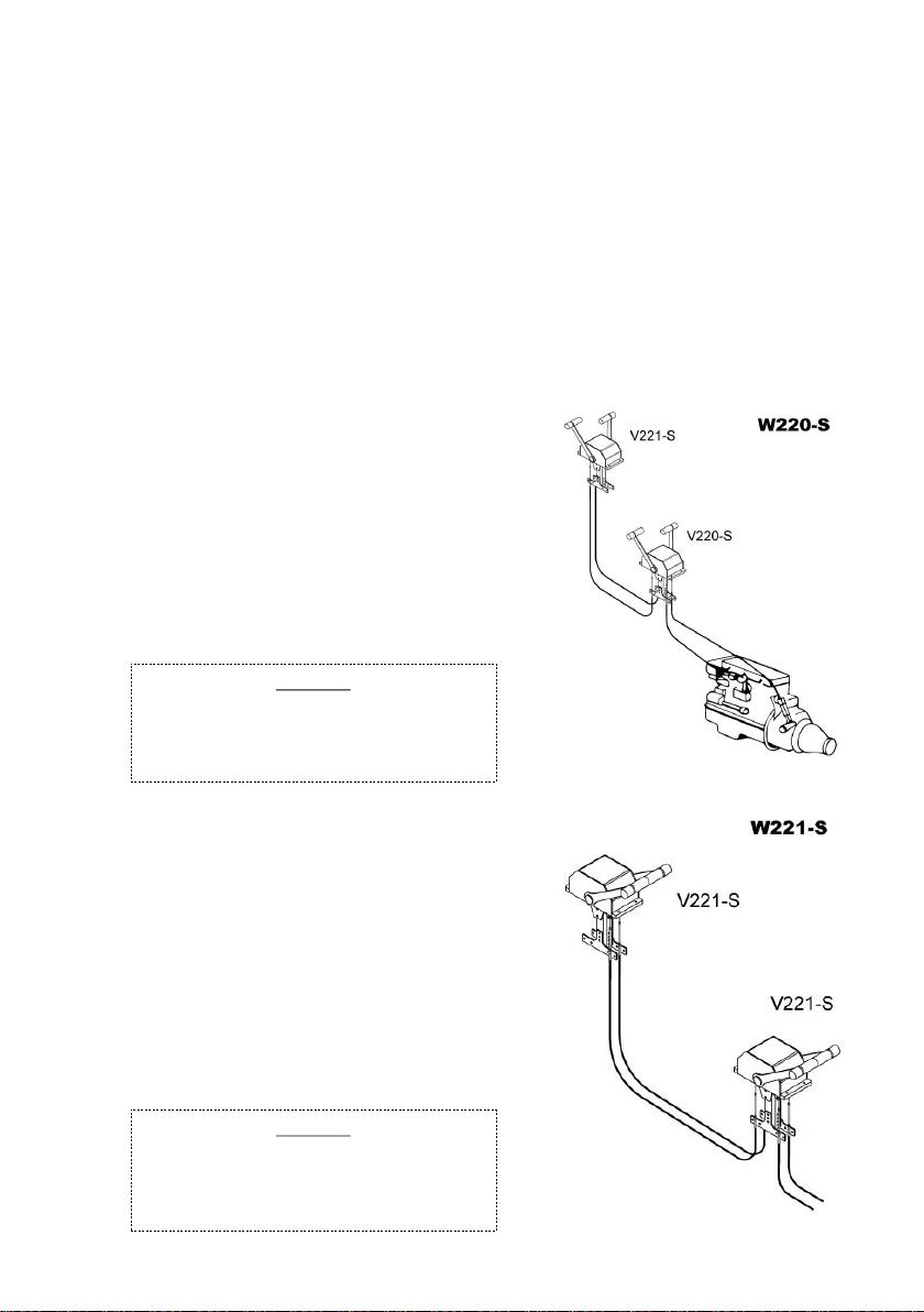
Conexión de mandos W220-S
En el conjunto W220-S para la operación de un motor
desde dos estaciones conectadas entre sí, el mando V220-S
funcionará como mando maestro y el V221-S funcionará como
mando esclavo.
Una vez instalados los dos mandos que forman los con-
juntos W220-S en las estaciones deseadas proceda a conectar
los cables siguiendo el dibujo adjunto.
Conecte los cables en las carreras correspondientes y
permiendo la conguración ra-empuja necesaria para ope-
rar el motor de forma correcta.
Conexión de mandos W221-S
En el conjunto W221-S para la operación de un propulsor
jet desde dos estaciones conectadas entre sí, uno de ellos fun-
cionará de master y otro de esclavo.
Una vez instalados los dos mandos que forman los conjun-
tos W221-S en las estaciones deseadas proceda a conectar los
cables siguiendo el dibujo adjunto.
Conecte los cables en las carreras correspondientes y per-
miendo la conguración ra-empuja necesaria para operar el
motor de forma correcta.
¡Atención!
Asegúrese que la conexión de los cables es la
correcta y verique el corrector funcionamiento
antes de arrancar el propulsor.
¡Atención!
Asegúrese que la conexión de los cables es la
correcta y verique el corrector funcionamiento
antes de arrancar el motor.

4
1. Intro.
The engine controls Mechanis allows the operator
a full control over the gear box and the engine
throle operang just one lever. Our controls can
be used by dierent push-pull cable but as default
controls are set for 33C universal cables.
2. Main features.
The control allows to the operator direct operaon
over:
Throle by pulling or pushing.
Gear box by pulling or pushing.
Please check the engine manufacturer manual in
case of doubt.
3. Cable connecon.
Place the pivot end on the cable terminal,
about half way of the thread.
Attach the cable to the control using the
cable clamps included in the equipment.
Place the pivot end on the desired hole as
shown in section 6 of this manual.
Aenon!
Always connect rst the cables to the control.
The throle and gear box connecon in the
engine must be done when the control has
been installed and the correct cable movement
is fully veried.
Secure the pivot end by seng the spindle.
Check the cable travel and movement by
operang the lever. Adjust if necessary.
Make sure that the cable terminals arrive
straight at their working ends and there are
no curves or excessive bends on them.
Use enough cable length. Avoid excessive
bends or curves in the cable.
Follow cable manufacturer instrucons at all
mes.
Connect the cable end terminals to the acon
devices of engine or equipment.
4. Instalación.
When selecng the place where the control will be
mounted, take into account for the maximum swing
that the lever can make and its total height. Make
sure that there are no internal or external elements
that could interfere the correct movement of the
mechanism. See drawing “Principal dimensions” at
the en of this manual.
Before turn on!
Verify the control correct operaon, with the
engine/equipment stopped. Check that there
are no undesirable fricons or malfuncons.
ATTENTION: The following instrucons contains important informaon that must be handle over to the
nal owner or operator of the engine control.
SAFETY INFORMATION:
Read this instrucons carefully before the installaon.
The incorrect use or an incorrect installaon may lead in the loss of control over the propulsionn
with a potencial damages to persons or things.
Mechanis S.L. does not accept responsibilies over installaons where Mechanis equipment or
devices has been used.
Mechanis S.L. does not accept responsibilies over equipment or devices modied partly or en-
rely without the wrien approval of Mechanis S.L.
Aenon!
Be sure that you choose the correct hole as per
cable features. An incorrect selecon could
lead in a cable and/or control damage.
5
V220S & V221S
Once the place has been selected, cut-o a mounng gap using the templates included.
Place the control in the resulng gap without the top cover and adjust as required.
Before marking the holes, put back the top cover to check the posion of the control is well cen-
tered and the gap fully covered.
Mark the holes, set aside the control and make the holes with a 6 mm drill.
Clean the area and install rmly the control on the console with the screws provided.
Set the cables as shown in “3.Cable connecon”.
Verify the correct funconing by operang the lever ahead and astern.
Adjust the lever fricon as shown “7.Fricon adjusng”.
Use some lubricant in order to keep the mechanism lubricated.
Install the top cover.
Control connecons for W220-S
The W220-S soluon is a two set control combinaon de-
signed for one engine instalaon for operated from two diferent
staons: one master and one slave. Such combinaon is form by
one V220-S (main staon) which will work as master and one
V221-S will work as slave (secondary staon).
Once both controls have been installed in their desered
staos, following above instrucons, cable connecons can be
done following aached drawing.
Connect the cables to their corresponding travels allowing
the push-pull seng required for the correct operaon of the
engine.
Control connecons for W221-S
The W221-S soluon is a two set control combinaon desig-
ned for one engine instalaon for operated from two diferent
staons: one master and one slave. Such combinaon is form by
one V221-S (main staon) which will work as master and one
V221-S will work as slave (secondary staon).
Once both controls have been installed in their desered
staos, following above instrucons, cable connecons can be
done following aached drawing.
Connect the cables to their corresponding travels allowing
the push-pull seng required for the correct operaon of the
engine.
Aenon!
Make sure that the cable connecon is the co-
rrect one and verify the correct funconing befo-
re start the engine.
Aenon!
Make sure that the cable connecon is the co-
rrect one and verify the correct funconing befo-
re start the engine.

6
5. Opciones de conexión de cables / Cable connecon sengs.
Opciones de conexión sólo cambiando pivotes de anclaje .
Connecon opons by changing pivot connector.
6. Recorrido disponibles / Travel opons.
Opciones / Opons Cambio-Avante / Gear box-Ahead Aceleración / Throle
1Tira / Pull Empuja / Push
2Empuja / Push Tira / Pull
Posición pivote
Pivot posion
Recorrido
Travel
Cable
137.5 (75) mm 33C & 43C
245/45 (90)
mm

7
7. Ajuste de la fricción / Fricon adjusng.
Ajuste la sensibilidad de fricción del mando apretando o aojando los tornillos de fricción según lo desea-
do.
Sensivity in the lever can be adjusted by ghtening or loosening the fricon adjusng nuts as desired.
8. Mantenimiento / Maintenance
Endulce el mando si está a la intemperie o si ha estado en contacto con agua de mar.
Controle regularmente el mecanismo para detectar piezas sueltas y el desgaste de las partes móviles.
Engrase periódicamente las partes móviles con un aceite lubricante hidrófugo.
Controle con regularidad los cables y sus conexiones para prevenir fallos.
Rinse with fresh water if the control is or has been in contact with sea water. Check periodically the me-
chanism in order to detect loose pieces and/or excessive wear in the moving parts. Use water-resistant
lubricant on the moving parts when necessary. Check regularly the cables and their connecons in order
to prevent failures.

8
9. Dimensiones principales / Principal dimensions.
This manual suits for next models
3
Table of contents
Other MECHANIS Remote Control manuals


