Mechatronics Eurosens Direct PH 100 User manual

`phone:+375(1771)7‐13‐00
e‐mail:office@mechatronics.by
Eurosensflowmetersoperationmanual

EUROSENSFuelflowmeters.Operationmanual.ver.1.6
www.mechatronics.by Page2|30
TABLEOFCONTENTS
TABLEOFCONTENTS ......................................................................................................................2
1. INTRODUCTION ..........................................................................................................................3
2. DESCRIPTIONANDOPERATIONOFFLOWMETERS ...................................................................3
2.1. Use..............................................................................................................................................................3
2.2. Designation..............................................................................................................................................4
2.3. Application...............................................................................................................................................4
2.4. Operationparametersandrecommendationsformodelselection....................................5
2.5. Dimensions..............................................................................................................................................6
2.6. Specification............................................................................................................................................6
2.7. Contentsofpackage..........................................................................................................................10
2.8. Flowmeterdesignandoperation................................................................................................11
3. WARRANTY...............................................................................................................................15
4. INSTALLATIONRECOMMENDATIONSFOREUROSENSFLOWMETER ......................................16
4.1. Visualinspectionoffuelflowmeter............................................................................................16
4.2. Estimationofvehiclecondition.....................................................................................................16
4.3. Commoninstallationrecommendations...................................................................................17
4.4. InstallationschemesofEurosensfuelflowmeters................................................................18
5. DIAGNOSTICSANDTROUBLESHOOTING..................................................................................24
6. STORAGE ..................................................................................................................................28
7. TRANSPORTATION....................................................................................................................28
8. UTILIZATION/RECYCLING..........................................................................................................29
9. DIMENSIONS.............................................................................................................................29

EUROSENSFuelflowmeters.Operationmanual.ver.1.6
www.mechatronics.by Page3|30
1. INTRODUCTION
TheOperationManualcontainsguidelinesandruleswhichrefertoEurosensfuelflow
meters(hereinafterFlowmeter),developedbyJSCMechatronics,Vilejka,Belarus
(mechatronics.by).
TheManualisintendedforspecialistswhoarefamiliarwithautomobilerepair,mounting
andmaintenanceandpossessprofessionalknowledgeinthefieldofelectricalandelectronic
equipmentofvariousvehicles.
Forqualityinstallationandoperationitisrecommendedtotraininstallersinthe
manufacturingcompanyorinthespecializedcenters.Theinstallerandthepersonresponsiblefor
themaintenanceofflowmetersshouldknowthestructureoffuelsystemsandtheiroperating
features.
Thesourcesofdangerduringtheinstallationandoperationoftheflowsensorsare
electricalcurrentandworkingfluid,whichcanbepressurizedto2.5MPaandhavetemperature
upto85°C.
WARNING!
Themanufacturerreservestherighttochangethetechnicalcharacteristicsoftheflow
sensorswithoutcompromisingwiththeconsumer,withoutleadingtoadeteriorationintheir
consumerqualities.
Installationanddeinstallationofflowsensorsmustbecarriedoutwithcompletelyno
excesspressureinthepipeline.
2. DESCRIPTIONANDOPERATIONOFFLOWMETERS
2.1. Use
Eurosensflowmetersaredesignedtocontrolavolumeflowandthevolumeofoil
productsthatflowthroughtheflowsensor,operateinfrigidandmildclimate.Thesensorsare
installedonstationaryormobileunitsforfuelconsumptioncontrolandforautomaticflowcontrol
andregulationindifferentbranchesofindustry,agricultureandtransport.

EUROSENSFuelflowmeters.Operationmanual.ver.1.6
www.mechatronics.by Page4|30
2.2. Designation
Table1
BrandTypeInterfacetypeAutonomous
feature
FlowrateДоп.
функция
EUROSENSDeltaPNA25005.I
Numberof
measuring
chambers
OutputinterfaceAutonomous
operation
without
externalpower
supply
Maxfuelflow
rateineach
measuring
chamber,
liters/hour
Improved
precision:
maxerror
+‐0,5%
I–LCD
display
Delta–2PorPH–
unnormalized
pulse(onlyfor
Direct)
А–possible100Nosymbol
–LCDis
not
installed
Direct–1PN–normalized
pulse
Nosymbol–
notpossible
250
232–normalized
pulse+RS232
interface
500
485–normalized
pulse+RS485
interface
RS–normalized
pulse+interface
RS232andRS485
CAN–normalized
pulse+CAN
interface
Nosymbol–
withoutinterface
2.3. Application
UseofEurosensflowmeters:
currentfuelconsumptionrecords;
registrationofmachineryworkingtime;
normalizingoffuelconsumptionlimitations;
fueltheftdetectionandprevention;
real‐timemonitoringandfuelconsumptionoptimization;
fuelconsumptiontestsforengines.

EUROSENSFuelflowmeters.Operationmanual.ver.1.6
www.mechatronics.by Page5|30
2.4. Operationparametersandrecommendationsformodelselection
FuelflowmetersEurosenscanmeasureflowofthefollowingliquids:
Table2
Dieselfuel
heatingoil
motorfuel
biofuels
Otherliquidfuelsandmineraloilwithakinematicviscosityof1.5to6mm2/s.
WARNING!
1)Alltheflowmetersarecalibratedfordieselfuelbythemanufacturer.Ifyouorderitto
measureanothertypeoffluid,pleaseindicateitsviscosity.
2)Whenworkingwiththeliquidkinematicviscosityofwhichismorethan6mm2/s,the
upperlimitofthemeasuringrangeofflowmeterspassportwillbelower,andthepressuredrop
acrosstheflowsensor‐higher.
3)Theamountofimpuritiesintheliquidshouldbenomorethan0.1mm.
4)Flowmeterismadeofmaterialsresistanttogasoline.However,whenworkingwith
gasolineoperationlifeofflowmetermaybeshorter.Allrisksassociatedwiththesafeoperationof
theEurosenssensorsonpetrolenginesareassignedtotheinstalleroftheequipment.
FuelflowmetersEurosensDirect(Delta)РN(RS)isauniqueequipmentthatallowstoset
individuallyanyvehicle(orothertypeoffuel)withthehelpofservicekitEurosensDestination,
takingintoaccounttheirindividualcharacteristics(airinthereturnline,hammering,temperature
inthesupplyandreturnlines,etc.).
FlowsensorsEurosensDeltacanbeusedindifferentialmode(defaultsetting),andinthe
summationmodeordirectsignalsdeliveryfromtheworkingchambers(inthiscasedifferential
flowmetercanmeasureupto1000liters/hourtotalfuelrate).Methodsofsettingsaredescribed
intheservicemanual(seepara.6).
RecommendationsforEurosensDirectmodelsselectiondependingonthepowerofthe
engineorboilerproductivity.
Table3
Powerofengine,KW(HP)Boilerproductivity,KWRecommendedmodelsDirect
XXXPN(PNI,P,RS)
Less100(136)Less600100
From100(136)to250(340)From600to1200250
From250(340)to600(816)From1200to3500500
WARNING!
1)Itisnotrecommendedtousetheflowmeterwiththemax.upperlimit.

EUROSENSFuelflowmeters.Operationmanual.ver.1.6
www.mechatronics.by Page6|30
2)Itisrecommendedtotakeafinaldecisiononthechoiceofthemodelafter
engine/boilerinspection.
3)Beforechoosingthemodelofflowmeteryoumustchooseinstallationschemeinfuel
line(directmeasurementordifferential).
RecommendationsforEurosensDeltamodelsselectionsdependingonthevaluesoffuel
consumptioninthesupplyandreturnfuellines
Table4
Minimumflowrate,
l/h
Maximumflowrate,
l/h
Recommendedmodels
DeltaXXXPN(PNI),XXX
5100100
10250250
25500500
WARNING!
1)Itisnotrecommendedtousetheflowmeterwiththemax.upperlimit.
2)Itisrecommendedtotakeafinaldecisiononthechoiceofthemodelafter
engine/boilerinspection.
3)Itisnotrecommendedtoinstalltheflowmeterwhenthereisanairinthesupplyor
returnline,andalsointhefuelsystemwithhigh‐capacitypomp,whenthefuelconsumptionisnot
large.
2.5. Dimensions
Seepara.10.
2.6. Specification
Table5.Eurosensflowmetermodifications
Eurosens
flowmeters
Qstart,
liters/hour
Qmin,
liters/hour
Qnom,
liters/hour
Qmax,
liters/hour
Amount
pulses/literAccuracy
DirectPH1000,525010098…102±2%
DirectPH2500,5512525098…102±2%
DirectPH5001,01025050048…52±2%
Single‐gateDirectPHmetershaveapulseoutput.Areusedinthedesignofthesensorsof
DirectPHofWaiting.Thismakestheminsensitivetotheeffectsoftheexternalmagneticfieldand
increasesthereliabilityoftheflowmeter.
Table5.‐continue
Eurosens
flowmeters
Qstart,
liters/hour
Qmin,
liters/hour
Qnom,
liters/hour
Qmax,
liters/hour
Amount
pulses/literAccuracy
DirectPN1000,5150100200±1%
DirectPN2500,52125250100±1%
DirectPN5001,0525050050±1%

EUROSENSFuelflowmeters.Operationmanual.ver.1.6
www.mechatronics.by Page7|30
Eurosens
flowmeters
Qstart,
liters/hour
Qmin,
liters/hour
Qnom,
liters/hour
Qmax,
liters/hour
Amount
pulses/literAccuracy
DirectPN100.050,5150100200±0,5%
DirectPN250.050,52125250100±0,5%
DirectPN500.051,0525050050±0,5%
DirectPN100I0,5150100200±1%
DirectPN250I0,52125250100±1%
DirectPN500I1,0525050050±1%
DirectPN100.05I0,5150100200±0,5%
DirectPN250.05I0,52125250100±0,5%
DirectPN500.05I1,0525050050±0,5%
I‐integratedLCDdisplay05‐higheraccuracy
PN‐meterwithanelectroniccircuitinapowerfulSTM32microprocessor.
Theelectroniccircuitprovidesthefollowingbenefits:
1.Improvedaccuracy.
2.SmartprocessingsignalsfromHallsensors.
3.Thecontrolinterventionintheoperationofthemeter.
4.Theflowmetercanmeasurenotonlythefuelconsumption,butalsothederived
parameters:theengineisrunning(boiler),thefuelconsumptionandtheoperatingtimein
differentmodes,duringthehandling,etc.TheseparameterscanbeconsideredeitherviatheK‐
lineinterface(PN.)OrviaRS232/RS485/CANinRS/CANflowmeters.
5.PNflowunlikeallcompetitivesamplescanbeinstalledwithouttheuseofacheck
valve,sincethealgorithmdeterminesthedirectionofthefuelflow.Thissignificantlyincreasesthe
reliabilityoftrouble‐freeengineoperationwiththemodifiedfuelcircuit.
Table5.‐continue
Eurosens
flowmeters
Qstart,
liters/hour
Qmin,
liters/hour
Qnom,
liters/hour
Qmax,
liters/hour
Amount
pulses/literAccuracy
Direct100I0,5150100‐ ±1%
Direct250I0,52125250‐ ±1%
Direct500I1,05250500‐ ±1%
DirectA100I0,5150100‐ ±1%
DirectA250I0,52125250‐ ±1%
DirectA500I1,05250500‐ ±1%
DirectPNA100I0,5150100200±1%
DirectPNA250I0,52125250100±1%
DirectPNA500I1,0525050050±1%
A‐autonomouscounter,built‐inbatterypowerI‐integratedLCDdisplay

EUROSENSFuelflowmeters.Operationmanual.ver.1.6
www.mechatronics.by Page8|30
Directmodelflowmeterswereintendedtodisplaylocalinformation,havenopulse
output.Requiresanexternalpowersupply.FlowmeterswithindexAarealsobuiltintothebattery
andallowthemetertooperateindependentlywithinthreeyears.DirectConsumptionIndicatorsA
singlemeofthefullrangeofbladeswitchesfunctioninsteadoftheHallsensor,whichiscausedby
considerationsofminimalpowerconsumption.DirectconsumptionindicatorsPNAIcanbe
poweredeitherbyexternalpowersupplyandtheinternalbattery.Haveapulseoutputand
display.
Table5.‐continue
Eurosens
flowmeters
Qstart,
liters/hour
Qmin,
liters/hour
Qnom,
liters/hour
Qmax,
liters/hour
Amount
pulses/literAccuracy
DeltaPN1000,51050100200±1,2%*
DeltaPN2500,520125250100±1,2%**
DeltaPN5001,04025050050±1,5%***
DeltaPN100I0,51050100200±1,2%*
DeltaPN250I0,520125250100±1,2%**
DeltaPN500I1,04025050050±1,5%***
DeltaPNA100I0,51050100200±1,2%*
DeltaPNA250I0,520125250100±1,2%**
DeltaPNA500I1,04025050050±1,5%***
Flowstosupply/consumptioninliters/hour:*45/10**90/20***160/30
A‐autonomouscounter,built‐inbatterypowerI‐integratedLCDdisplay
PN‐Normalizedpulse.Processorbuilt‐in.
TheEurosensDeltaDifferentialThesaurushasthefollowinguniquecharacteristics:
1.Paymentfueltemperaturediffersinbothchambers.
2.TheuseofHallsensorsprovideshighreliabilityandresistancetotheexternalmagnetic
field.
3.MaterialsHighqualitycameraandmachiningallowsyoutoseta3yearwarranty
periodwithoutlimitingthecameraresource.
4.Abilitytoaddfuelflowinsteadofsubtraction.
5.Measuringnotonlythefuelconsumption,butalsotheoperatingtimer,andthe
operatingtimeandfuelconsumptioninthepartialengineoperatingmodes,whicharesetlimit.
Table5.‐continue
Eurosens
flowmeters
Qstart,
liters/hour
Qmin,
liters/hour
Qnom,
liters/hour
Qmax,
liters/hour
Amount
pulses/literAccuracy
DirectRS1000,5150100200±1%
DirectRS2500,52125250100±1%
DirectRS5001,0525050050±1%
DirectCAN1000,5150100200±0,5%
DirectCAN250.050,52125250100±0,5%

EUROSENSFuelflowmeters.Operationmanual.ver.1.6
www.mechatronics.by Page9|30
Eurosens
flowmeters
Qstart,
liters/hour
Qmin,
liters/hour
Qnom,
liters/hour
Qmax,
liters/hour
Amount
pulses/literAccuracy
DirectCAN500.051,0525050050±0,5%
DirectRS100I0,5150100200±1%
DirectRS250I0,52125250100±1%
DirectRS500I1,0525050050±1%
DirectCAN100I0,5150100200±0,5%
DirectCAN250I0,52125250100±0,5%
DirectCAN500I1,0525050050±0,5%
DeltaRS100 0,51050100200±1,2%*
DeltaRS250 0,520125250100±1,2%**
DeltaRS5001,04025050050±1,5%***
DeltaRS100I0,51050100200±1,2%*
DeltaRS250I0,520125250100±1,2%**
DeltaRS500I1,04025050050±1,5%***
DeltaCAN100 0,51050100200±1,2%*
DeltaCAN250 0,520125250100±1,2%**
DeltaCAN500 1,04025050050±1,5%***
DeltaCAN100I0,51050100200±1,2%*
DeltaCAN250I0,520125250100±1,2%**
DeltaCAN500I1,04025050050±1,5%***
Flowstosupply/consumptioninliters/hour:*45/10**90/20***160/30
I‐CANLCDintegrateddisplay‐CANinterfaceRS‐RS232/RS485interface
EurosensflowmeterscanalsohaveaseriesofRS232/RS485datainterfaces,aswellas
theCANinterfacebyRS232/RS485operationofthedatainterfaceprotocolispossibleEurosens
DeltaorMODBUS.CANinterfaceisinaccordancewiththeSAEJ1939specification.
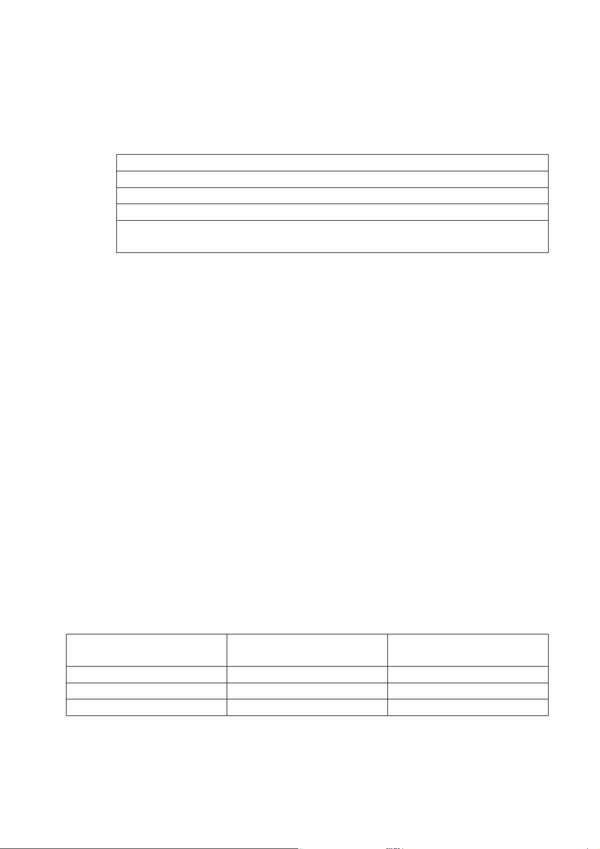
Table.6.Mainspecifications
Parameter,measurementunitsValue
Maxpressure,MPa2.5
Nominalpressure,MPa0.2
Filteringdegreeofmeasuredfluid,mm,notmore
than
0.08
ConnectionthreadM14x1.5M16x1.5
Pressuredropatmaximumflowrate,nominal
pressure,dieselfuelat20°С,MPa,notmorethan
0.02
Supplyvoltagerange,Vfrom10to50(from9to32)*

EUROSENSFuelflowmeters.Operationmanual.ver.1.6
www.mechatronics.by Page10|30
Parameter,measurementunitsValue
Currentconsumptionat12V,mA,notmorethan50
Currentconsumptionat24V,mA,notmorethan25
Temperaturerange,°С from‐40to+80**
Environmentrelativehumidityatt40°C,%,not
morethan
95
VibrationresistanceMax.accelerationto100m/s2inthe
frequencyrangefrom
5to250Hz
ResistancetoaggressiveenvironmentsOilandpetrolresistance
ElectromagneticcompatibilityECERegulations10.04
OveralldimensionsSeepara.10
*forflow
meterstypesDirectP(PH).
**Dataisdisplayedinenvironmenttemperaturerangefrom‐20to+60°Cforflow
meterswithbuilt‐indisplay.
2.7. Contentsofpackage
Table7
№ PositionQuantity
1. Flowmetereurosens1
2. Passport1
3. Cable*1
*Canbesuppliedseparately.

EUROSENSFuelflowmeters.Operationmanual.ver.1.6
www.mechatronics.by Page11|30
2.8. Flowmeterdesignandoperation
2.8.1.Operationprinciple
Theflowsensormeasurestheamountoffuelflowingthroughthemeasuringchamber.
Pressurizedfluidcomingthroughtheinletnozzleflowsensorintheinletofthemeasuring
chamber,thepistonslidesalongtheinnersurfaceofthechamberandsimultaneouslyslidesalong
thejumper.Thepistondisplacesfluidenclosedinitinsideandoutsideofthepistonchamber
throughitsoutlettotheoutletport(see.Fig.1).
Theenclosureprovidestheorientationoftherotationaxesofthecoverpinwiththe
magnetsandthehubofthepiston,thankstothenumberofdimensionsofthecoverandthe
housingwhichprovidestheoptimumrotationoftheringchamber.
Duringonerotationofthepistonvolumeofliquidequaltothevolumeofchamberis
displaced.Inthiscase,theelectronicpositionsensorsgeneratepulsesastheturnoverofthe
piston,whicharetransmittedtotheelectroniccontrolunitfortheselectedinterface.
Fig.1.EUROSENSmeasuringchamberoperation:
1–inlet,2–outlet,‐fluidisenteringthemeasuringchamber,‐fluidin
measurementprocess,‐fluidisgoingtoleavethemeasuringchamber.
2.8.2.Operationmodes
Table8
Flowmeter
modification
Flowrate,l/hourInterference
eurosensXYZV,
гдеY(max.flow
rate)=
l/hour
NormalflowrateQ
0
<Q≤Qma
x
Tampering
Theimpactof
constant
magnetic
field
formorethan
10seconds
Idle Normal
operation
Overload
100<2 2‐7070‐100>100Attemptsare
fixed
250<5 5‐200200‐250>250
500<1010‐400400‐500>500

EUROSENSFuelflowmeters.Operationmanual.ver.1.6
www.mechatronics.by Page12|30
2.8.3.Informationscreens(flowmeterswithLCDdisplay)
Table9
DirectI*DeltaI*
№
Screen
Parameter №
Screen
Parameter
1
2
3
4
5
6
7
8
9
10
11
12
Totalconsumption,l
Idleconsumptionl
Consumptionundernominalload,l
Overloadconsumptionl
Cheatconsumption,l/h
Negativevolume,l
Totaloperatingtime,Hour**
Interventiontime,hour***
Flowrate
Chambertemperature,deg.,C
Batterycharge,%
Firmwareversion
1
2
3
4
5
6
7
8
9
10
11
12
13
14
15
16
17
18
19
Totalconsumption,l
Idleconsumptionl
Consumptionundernominalload,l
Overloadconsumption,l
Cheatconsumption,l
Negativevolume,l
Totaloperatingtime,h**
Interventiontime,h***
Supplyflowrate,l/h
Thetotalvolumeofsupply,l
Cheatvolumeofsupplychamber,l
Supplyflowrate,l/h
Temperatureinsupplychamber,C
Thetotalvolumeofreturn,l
Cheatvolumeofreturnchamber,l
Returnflowrate,l/h
Temperatureinreturnchamber,C
Batterycharge,%
Firmwareversion
*Theseparameters(plussomeadditional)arealsodisplayedinconfigurationsoftwareon
allflowmetersPN(RS)(EurosensDestinationservicekitisneeded).
**forallmodels,asideAutonomous
***onlyforAutonomousmodifications
2.8.4.Cheatprotectionfeatures.
Inordertoavoidcheatingofflowsensor,itsdamageorblockingDeltaandDirectPN,RS
modelshasthefollowingmodesofprotectionagainstcheatingactionsofthirdparties:
1)Mode"Cheat"‐protectionagainstcheatinginordertoincreasethecountervalueof
theconsumedfuel(eg.airblowing).Cheatusuallyleadstoarapidincreaseinfuelconsumption
thatexceedsthemaximumone.Electroniccircuitboardofaflowsensordetectsoverstatedcosts,
whilefuelmeteroperationisstoppedandcounter"Cheat"isactivated,whichrecordstheamount
offuelflownthroughtheflowsensorathighspeed.
Mode"Cheat"isautomaticallyexitedinfewsecondsafterthenormalizationofconditions
offlowsensorwork.

EUROSENSFuelflowmeters.Operationmanual.ver.1.6
www.mechatronics.by Page13|30
2)Mode"Intervention"‐undertheinfluenceofanexternalmagneticfield,theflow
sensordetectsanattempttointerfereandastheresultthesensoritselfisoperatinginstandard
modeandtheexposuretimeisrecordedinaspecialcounter"Interventiontime."
Mode“Intervention”isautomaticallyexitedinfewsecondsaftertheendofattemptsto
interfere.
3)Sealingofconnections‐mountingaccessories(fuelconnectors,clamps,etc.)supplied
byJSCMechatronicshaveholesforsealing,thatallowstodeterminethefactsofunauthorized
interferenceinthefuelsystemaftertheinstallationoftheflowsensor.
2.8.5.CharacteristicsofthepulsesignalofEurosens
Flowmeterwithnon‐standardpulse(modelP)hasanoutputpulsesignalshowninFig.2.
Foreachflowmeterthenumberofpulsesgeneratedbyflowingof1literoffuelthrough
themeasuringchamberisshowninthedatasheetfortheproduct(passport).
ThetypeandcharacteristicsoftheoutputsignalsEUROSENSXP(PN)ZVareshownin
Figures2,3andtables10,11(seebelow).CharacteristicsoftheoutputsignalsEUROSENSXRSZV
matchthespecifiediteminthedigitalprotocols.
Fig.2.OutputsignalofEUROSENSXР(PH)ZV(alsoseetables10,11).

EUROSENSFuelflowmeters.Operationmanual.ver.1.6
www.mechatronics.by Page14|30
Fig.3.OutputsignalofEUROSENSXРN(RS)ZV(alsoseetables10,11)
Table10OutputsignalofEUROSENSXРN(PH,Р)ZV
ModificationUhigh,VUlow,V
DirectP(PH)1000.9Ubat*0.7V
DirectP(PH)2500.9Ubat*0.7V
DirectP(PH)5000.9Ubat*0.7V
DirectPN(A)1000.7(Ubat–0.4)**1.4V
DirectPN(A)2500.7(Ubat–0.4)**1.4V
DirectPN(A)5000.7(Ubat–0.4)**1.4V
DeltaPN(A)1000.6(Ubat–0.8)***0.7V
DeltaPN(A)2500.6(Ubat–0.8)***0.7V
DeltaPN(A)5000.6(Ubat–0.8)***0.7V
*Whentheinputloadresistance(forexample,theinputofgps‐trackerisnear50
kiloohm)
**Whenthepull‐upoutputtopowercircuit(Ubat)isonforDirectPN.
***Whenthepull‐upoutputtopowercircuitison(Ubat)forDeltaPN.Inthelatest
versionsofsensors0.8(Ubat–0.8).

EUROSENSFuelflowmeters.Operationmanual.ver.1.6
www.mechatronics.by Page15|30
Table11.OutputsignalofEUROSENSXРN(P)ZV
Modification Signalparameters,ms
Tpulse
max
Tpulse
min
T
lowmax
(0,6Tpuls)
T
lowmax
(0,5Tpuls)
T
lowmax
(0,4Tpuls)
T
lowmin
(0,6Tpuls)
T
lowmin
(0,5Tpuls)
T
lowmin
(0,4Tpuls)
DirectP10090001805400450036001089072
DirectP250720014443203600288086,47257,6
DirectP500720014443203600288086,47257,6
DirectPH10090001804500 90
DirectPH25072001443600 72
DirectPH50072001443600 72
DirectPN(A)10018000180500 90
DirectPN(A)2507200144500 72
DirectPN(A)5007200144500 72
DeltaPN(A)10018000180500 90
DeltaPN(A)25036000144500 72
DeltaPN(A)50072000144500 72
Theactualinformationaboutthecompatibilityofparticularmodelsofgps‐trackerwith
Eurosensfuelflowmetersandalsotherecommendationsontheirconnectionandadjustmentyou
canseeonourweb‐site–www.mechatronics.by
3. WARRANTY
1) ThemanufacturerguaranteesthecomplianceofEurosensfuelflowmeterswiththe
presenttechnicalrequirements,providedthatstorage,transportandoperationconditionsare
observed,andalsotheinstructionsforusethatsetoutinthistechnicalrequirementareobserved
aswell.
2) Productwarrantyperiod‐36monthsfromthemanufacturingdate.
3) Guaranteedstoragelife‐6monthsfromthemanufacturingdate.
4) Incasewhensensorsaresuppliedascomponentsbetweenenterprises,guaranteed
serviceandstoragelifeshouldbespecifiedintheContractbetweentheseenterprises.
5) Nowarrantyismade:
‐ifthereisamechanical,chemical,thermal,electricorotherdamageofdevice;
‐inthecaseofwarrantysealsandlabelsabsence;
‐ inthecaseofdevicebreakdownbecauseofinappropriatestorage,installationor
mishandling;
‐inthecaseofdevicebreakdownbecauseofitsinstallationonthevehicle(orotherfuel
consumer)thatisnotingoodrepairorbecauseofdeviceoperationonthefuelconsumersthat
arenotingoodrepair,whatleddirectlytothedamageofthedevice;
‐inthecaseofopening,repair,installationormodernizationofdevicebyunauthorized
persons;
‐ whenthedeviceoperatesunderconditionsthatdonotcorrespondtopassport
characteristicsofthedevice;
‐Inthecasewhenthereisn’theldaperiodicmaintenanceinaccordancewithpara.6of
thisoperationmanual;

EUROSENSFuelflowmeters.Operationmanual.ver.1.6
www.mechatronics.by Page16|30
‐inthecasepassportondevice(specification)absence.
4. INSTALLATIONRECOMMENDATIONSFOREUROSENSFLOWMETER
ThissectioncontainsgeneralrecommendationsonEurosensflowmeterinstallation.
4.1. Visualinspectionoffuelflowmeter
Beforestartingflowmeterinstallation,itisrequiredtoinspectitvisuallyforthepresence
ofthepossibledefectsthatcanberesultedfromtransportation,storageorcarelessuse:
‐ visibledamagesofthemeterbody,fittings,bracket,display,interfacecableand
connector;
‐theplayofcomponentpartsrelativetoeachotherandthegapsbetweenthem;
‐ immediatelybeforeinstallationitisrecommendedtochecktheconnectionof
flowmetertopowersupplybytheminimalamountoffuelorairsupplying(10‐40l\h,pressure–
notmorethan0.3atm)andcheckingtheblinkingonthesensorcoverduringthesupplyofalarm
LEds.
Contactthesupplierifanydefectsaredetected.
4.2. Estimationofvehiclecondition
Beforeflowmeterinstallationthevehicleconditionshouldbeestimatedtomakea
conclusionregardinginstallationpossibility.
Table12.Sequenceofactions
№ ActionNormalstateRecommendationsin
caseofmismatch
condition
1. Toinspectthefuellinesfor
damagesorfuelleaks
NoleaksTheCustomereliminates
theleaks
2. Tochecktheengine
operationfor(5…10)minutes
atidle
Theengineshouldworkregularly,
doesnotfail(stall);thereshouldn’t
beanylossofpowerunderload
TheCustomereliminates
themalfunctions
3. Tochecktheengine
operationfor(5…10)minutes
underloadormotion
Theengineshouldworkregularly,
foesnotfail(stall)
TheCustomereliminates
themalfunctions
4. Tocheckasystemvoltageby
voltmeter
Forthesystemvoltage12Vthe
operatingvoltageshouldbeinthe
rangeof10to18V.
Forthesystemvoltage24Vthe
operatingvoltageshouldbeinthe
rangeof10to32V.
TheCustomereliminates
themalfunctions
5. WheninstallingDeltafuel
flowmeters‐tocheckif
thereisanairinreturnline
Thereshouldn’tbeanyairItisneededtoinstall
Deaeratoror
TheCustomereliminates
themalfunctions
6. Tochecktheamountoffuel
surpluses,thatareremoved
Iftheamountoffuelsurplusesis
significant,theaccuracyof
ToinformtheCustomer;
ifpossible–tomake

EUROSENSFuelflowmeters.Operationmanual.ver.1.6
www.mechatronics.by Page17|30
№ ActionNormalstateRecommendationsin
caseofmismatch
condition
fromtheenginenozzles
throughthereturnfuelline
measurementdecreases,asfuel
surplusesflowbackinthetankand
arerecountedbyfuelflowmeter
amendmentsin
recordingsystemsetup
7. Tocheckthepressureinfuel
systemwiththehelpof
manometer
Hydraulicresistanceofthechosen
sensorinnominalmodeshouldn’t
reducethepressurebymorethan5
%
Tocomparewith
pressureafterflowmeter
installation
8. Checkthevehicleground
Theresistancebetweenconnection
pointandclamp“‐“ofbattery
terminalshouldn’texceed1Ohm.
TheCustomereliminates
malfunctions
VehicleinspectionReportshouldbemadeandsignedbasedontheinspectionresults.
Thecustomershouldeliminateanymalfunctionsrecordedtothereportbeforeflowmeter
installation.
WARNING!
1. Thevaluesofmaximumandminimalfuelconsumptioninsupplyandreturnlinescould
beknownfromthepassportoroperationcharacteristicsofcapacityofthepompthatisinstalled
atthevehicle,orbyexperimentalmethod–byconnectionoffuelflowmeterwithdisplay(for
example,DirectPNAI)tothescheme.
2. Itisnotrecommendedtoinstalldifferentialfuelflowmetersinthefuelsystemwith
high‐performancepompandsmallfuelconsumption.Forexample,ifpompperformanceis300
l\h,fuelconsumptionis(5…6)l\handrelativemeasurementerrorinsupplyandreturnlinesis1%,
thentheabsolutemeasurementerrorcanbeupto6l\h.Whatisequaltotheamountoffuel
consumedbyengine.
3. Contraindicationtodifferentialflowmeteristhefactofairpresenceinthesupplyor
returnfuelline.
4.3. Commoninstallationrecommendations
WARNING!
Thischapterprovidesthespecialcasesofengineoperationschemes.Carefullyreadthe
technicaldocumentationofthevehicleonwhichtheflowmeterisinstalled,beforemakinga
decisionofitscompatibilitywiththevehicle.
Toinstalltheflowmeteryouneed:
•aflowmeter
•ServicekitEurosensDestination
•PC
•mountingkit(soldseparately);
•Handtools(wrenches,screwdrivers).
Theflowsensorcanbemountedinanyposition:vertically,horizontallyorinclined.Do
notkinkthecableandfuelpipes(fuelsupplylines).Itisrecommendedtomountthesensor

EUROSENSFuelflowmeters.Operationmanual.ver.1.6
www.mechatronics.by Page18|30
horizontallyforthebestoperation.Thesensorshouldbesecuredbyatleastthreepointsonthe
plane.
WARNING!
Whensettinguponavehicleitisprohibitedtodrillthebaseframe!Ifit'simpossibleto
mountthemountingplatewithscrews,youcanusespotwelding.
Pleaseobservethefollowingrules:
1. Wheninstallingtheflowmeteronanyequipmentinordertoavoidtheentryofdirt,
rubberparticles,cordandmetalsthatareresultedfromlinecuttingandthreadscrewing,ITIS
NEEDEDtoinstalladditionalplastic(orifthepressureinsystemishigh–metallic)fuelfilters
justbeforeeverychamberandthefirststart‐uptomakewiththem.Afterhalfanhour’sworking
ofthesystemthefilterscouldbeaccuratelydismantled.
2. Ifthefuelsystemishighlycontaminated,itisneeded:
‐toperformamaintenanceworkwithreplacingtheregularfilter
‐toinstalladditionalfilters,iftherearenoregularones
3. Flangesandthreadedconnectionsmustbecleanduringconnection.
4. Wheninstalling,useonlynewcoppersealingfromthemountingkit.
5. Fuellinesmustbeprotectedfromexternaldestructiveeffects.
6. Itisnotallowedtoreducetheinternalcrosssectionofthefuellinesonthebends.
7. Fuelhosesonthevehiclemustbefixedevery0.5m.
8. Fuelhosesinlengthshouldhaveasmalllengthmargintocompensatetemperature
changes.
9. Donotinstallaflowsensorontheelementsofthevehicle,subjecttostrong
vibrationsandheat.
10. Therubberfuellineshouldbeconnectedtothefuelsystemelementswiththehelp
ofpivotbracketorflow‐throughfittingandtobefastenedwithclamporcrimpsleeve(itis
advisable)ofrequireddiameter.
11. Afterflowsensorisinstalleditisnecessarytoremoveairfromthefuelsystem.
12. Alldetachableandthreadedconnectionsthataresituatedonthefuellinesection
“engine–flowmeter,flowmeter–engine”(includingareliefvalve)shouldbesecurelysealed!
13. Donotuseflowmeterwithmaximumflowratelowerthantheactualoneonthe
equippedvehicleordieselgenerator.
14. Itisnotrecommendedtouseinternalorexternalfilterswithpetrolgauze(thecell
areaislessthan0.6microns)inthewiringscheme.Therecouldbefailuresinworkoffuel
systematsubzerotemperatures.
4.4. InstallationschemesofEurosensfuelflowmeters
4.4.1.Typicalfuelsupplysystem
ThemostcommonschemeofthefuelsystemofdieselengineisshownontheFig.4.

EUROSENSFuelflowmeters.Operationmanual.ver.1.6
www.mechatronics.by Page19|30
Fig.4.Typicalfuelsystem
Fuelbackuppump(hereinafter–supplypump)suppliestotheinletoffuelinjectionpump
(hereinafter‐fuelpump)significantlylargeramountoffuelthanisconsumedineachcycleof
operationoftheengine.Excessfuelfromthefuelpumpandinjectorsoftheengineisdischarged
backintothetankthroughreliefvalve.
4.4.2InstallationoffuelflowmetersEurosensDirect"Onpressureside"scheme
InstallationoffuelflowsensorEurosensDirect"Onpressureside"schemeintendsthe
installationofaflowsensorbetweenfuelfinefilterandfuelpump,wherefuelisflownunder
pressure.
Fig.5.EurosensDirectinstallation«Onpressureside».Checkvalveisnecessaryonlyfor“DirectP,
PH”series.

EUROSENSFuelflowmeters.Operationmanual.ver.1.6
www.mechatronics.by Page20|30
Fuelpumpreturnlineshouldbechangedtocirculatefuelinasmallercircle:movethe
returnlinefromtheoutputofthehighpressurepumptothefinefilterandlocktheoutputofthe
highpressurepump.
Forcorrectoperationofthemodifiedfuelsystemyouneedtomovebypassvalvefrom
fuelpumpthatmaintaintherequiredconstantpressure(1...1.5)barintheareaofthefinefuel
filterandinletofhighpressurepump.Attheoutputoftheflowsensoracheckvalve(0.15...0.5)
atmshouldbeinstalled,whichpreventsthefuelflowthroughtheflowsensorintheopposite
direction,aswellasreducestheimpactofhydrocracksinfuelsystem.
Thus,excessfuelfromsupplypumpwillgobacktothetankfromtheinletoffinefilter
andthrougheurosensDirectwillflowonlytheamountoffuelwhichisconsumedbyengine.
Advantagesofthescheme"onpressureside":
•EurosensDirectissetaftertheregularfuelfinefilter;
•Reducedflowresistanceonthesupplypumpsuctionside.
•Returnflowheatsfuelinthetank.
Disadvantagesofthescheme"onpressureside":
•coolingoffuelpumpdecreasesalittle;
•returnlinetemperatureislowerthaninthestandardfuelscheme.
4.4.3InstallationofEurosensfuelflowmeterunder"suctionscheme"
Installationoffuelmeter"onsuctionside"supposestheinstallationofaflowsensorin
theareaofthefuelsystem,wherethefuelflowisforcedbysuctioncreatedbysupplypump.
WARNING!
InstallationofEurosensDirectflowmeter"onsuctionside"requiresanadditionalfuel
filteronthefuellinefromthetanktotheflowsensor.
AspecialcaseofDirectflowmeterinstallationunder"suctionscheme":
ToinstalltheDirectunderscheme"onsuction"intheenginefuelsystemwithfuelbackup
pump(see.Fig.6),itisnecessarytousethesitebetweenthefuelpre‐filterandtheinletoffuel
backuppump.
This manual suits for next models
56
Table of contents
Popular Measuring Instrument manuals by other brands

Bacharach
Bacharach MONOXOR XR quick start guide

Leuze electronic
Leuze electronic TNT 35 Connecting and operating instructions

FISCHER
FISCHER DA30 instruction manual

KMB
KMB SMY 133 operating manual

Extech Instruments
Extech Instruments ExStik II EC400 user manual

CAMBRIDGE
CAMBRIDGE CSW-10AT-CS Setup & operation