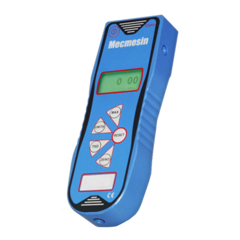
Mecmesin AFTI Installation and operating manual

AFG/AFTI Mk 4
Service and Repair Manual
Number 022-614
Issue Number: 09
Page 1 of 47
PDF copy stored in approved
location by: (click on signature for
validation)
Paper copy printed from approved PDF source
by:
Name
Signature
Date

AFG/AFTI Mk 4
Service and Repair Manual
Number 022-614
Issue Number: 09
Page 2 of 47
PDF copy stored in approved
location by: (click on signature for
validation)
Paper copy printed from approved PDF source
by:
Name
Signature
Date
1. Contents
1. Contents.............................................................................................................. 2
2. Change History.................................................................................................... 3
3. Product variants .................................................................................................. 4
4. Warnings and cautions: -..................................................................................... 5
5. Latest software version: - V1.12.......................................................................... 5
6. Inspection procedure........................................................................................... 6
7. Notes about 300-157-V03 ................................................................................... 8
8. PCB replacement (300-157-V02/3)..................................................................... 9
9. Sounder replacement (328-005)........................................................................ 12
10. Display replacement (301-028-V01)............................................................... 13
11. Configuration of display 301-028 V1.06 –V1.10............................................. 14
12. Configuration of Display 301-028-V01 (V1.12) ............................................... 19
13. Charging socket replacement (329-355)......................................................... 22
14. Keypad Membrane/Front Cover Plate replacement........................................ 23
15. Load cell removal............................................................................................ 24
16. Load cell stud fitting........................................................................................ 25
17. Load cell refitting............................................................................................. 27
18. Battery lid/insulator replacement..................................................................... 27
19. Firmware version –Identification.................................................................... 28
20. Firmware release notes .................................................................................. 28
21. PCB Conversion - AFTI to or AFG or Tornado or Orbis.................................. 34
22. Latency........................................................................................................... 35
23. Display contrast setting................................................................................... 36
24. AFG & AFTI Analogue Output. ....................................................................... 37
25. Fault finding.................................................................................................... 39
26. Spare parts list................................................................................................ 41
27. Assemblies and parts from China................................................................... 42
28. Exploded parts diagram.................................................................................. 44
29.Changes to 300-157-V03................................................................................ 46
AFG/AFTI Mk 4
Service and Repair Manual
Number 022-614
Issue Number: 09
Page 3 of 47
2. Change History
Iss.
Date
Effective
S.No.
DCR
No.
Author
Document / clarification
Change
Mechanical Change
01
04-09-07
Service
Initial issue (020)
02
17-04-09
TF
Prefix 022 & V1.07
03
05-11-09
TF
V1.09, software release, Contrast
setting, Latency & Analogue
sections added.
04
08-02-10
1661
TF
V1.10, 1000N / 2500N Pinned load
cells, Bad 8515 version error
message.
05
25-08-11
1847
1876
TF
mV offset pins to use, 1000N
Pinned load cell removal
V1.12
Config 301-028-V01 LCD
Load cell stud removal
06
26-10-12
2038
TF
LCD behaves unusually.
LCD Config 3179, 3178. EEPROM
Code 9876
06A
-S01 removed from 400-175 & 400-
034
07
23/03/15
2318
TC
Product variants added. Sub-
assemblies added.
Add digital/analogue output info
08
24/06/15
2416
SL
09
04/04/17
2748
GG
PED Open Issue 10068 - Update
service manual change history table to
include Sno. & Mechanical change
columns –Page 20 PNo. updated

AFG/AFTI Mk 4
Service and Repair Manual
Number 022-614
Issue Number: 09
Page 4 of 47
3. Product variants
850-412
Description
Capacity
Output
850-412
AFG 2.5N
2.5N
Digital
850-412-BA
AFG MK4 2.5N + CAL ANALOGUE
2.5N
Analogue
850-413
Description
Capacity
Output
850-413
AFG 5N
5N
Digital
850-413-BA
AFG MK4 5N + CAL ANALOGUE
5N
Analogue
850-414
Description
Capacity
Output
850-414
AFG 10N
10N
Digital
850-414-BA
AFG MK4 10N + CAL ANALOGUE
10N
Analogue
850-415
Description
Capacity
Output
850-415
AFG 25N
25N
Digital
850-415-BA
AFG MK4 25N + CAL ANALOGUE
25N
Analogue
850-416
Description
Capacity
Output
850-416
AFG 50N
50N
Digital
850-416-BA
AFG MK4 50N + CAL ANALOGUE
50N
Analogue
850-417
Description
Capacity
Output
850-417
AFG 100N
100N
Digital
850-417-BA
AFG MK4 100N + CAL ANALOGUE
100N
Analogue
850-418
Description
Capacity
Output
850-418
AFG 250N
250N
Digital
850-418-BA
AFG MK4 250N + CAL ANALOGUE
250N
Analogue
850-419
Description
Capacity
Output
850-419
AFG 500N
500N
Digital
850-419-BA
AFG MK4 500N + CAL ANALOGUE
500N
Analogue
850-420
Description
Capacity
Output
850-420
AFG 1000N
1000N
Digital
850-420-BA
AFG MK4 1000N + CAL ANALOGUE
1000N
Analogue
850-421
Description
Capacity
Output
850-421
AFG 2500N
2500N
Digital
850-421-BA
AFG MK4 2500N + CAL ANALOGUE
2500N
Analogue

AFG/AFTI Mk 4
Service and Repair Manual
Number 022-614
Issue Number: 09
Page 5 of 47
4. Warnings and cautions: -
NEVER DISCONNECT THE LOAD CELL FROM THE PCB WITH THE POWER
"ON"
NEVER REMOVE THE BATTERIES FROM THE PCB WITH THE POWER "ON"
IF APPLICABLE, CORRESPONDENCE FROM THE CUSTOMER SHOULD BE
READ BEFORE EXECUTING ANY FORM OF TEST
Antistatic procedures are to be used throughout this work instruction and at all times
when handling populated printed circuit boards (PCBs). Refer to Mecmesin
Procedure 010-016 (Mecmesin internal document).
This manual describes the inspection procedure, where specific keys will need to be
pressed to enter certain modes of the software. Words typed in bold and italic
represent the keys on the keypad, i.e. ENTER or UNITS.
5. Latest software version: - V1.12
The version of software is displayed on the gauge start-up screen (bottom left-hand
corner).
Mecmesin Limited recommends that instruments have the latest version of
software installed.
AFG/AFTI software can be upgraded to the latest version (see section 18 for
software history) using the following:
020-332: AFG4/ORBIS2/TORNADO2 Gauge Serial Programming Work
Instruction.
840-210: Programming kit for gauges.
PLEASE NOTE: - When you have completed the reprogramming of the AFG,
Mecmesin Limited recommends verification of the product to confirm correct
instrument operation.
Note: Correct reprogramming of the unit will NOT affect the Calibration data.

AFG/AFTI Mk 4
Service and Repair Manual
Number 022-614
Issue Number: 09
Page 6 of 47
6. Inspection procedure
1) Visually inspect the instrument case, display and communication port for damage.
2) The front label and serial number label should be legible and free from damage.
3) Attach a long extension rod, checking the load cell stud thread is not damaged.
The long extension rod should protrude perpendicularly from the load cell (check
with jig ref. no: 115-001 Mecmesin internal fixture).
4) Turn the instrument on. The audible alarm should sound and the visual alarm
LED’s should light whilst the on key is depressed
5) Check the operation of each key
6) Do not inspect the gauge with the “low battery” symbol showing (see below)
If the low battery symbol is showing, either:
Replace the batteries.
Check the existing batteries are not alkaline type and use the mains
adaptor/battery charger.
If alkaline batteries are fitted, fit a serviceable set or remove them and use the
mains adaptor/battery charger.
7) Check the loadcell offset: Software pre V1.01
The Calibration menu displays a password menu and allows the user to check for
load cell offset if overload is suspected.
Lay the gauge on its back without any accessories attached on a flat level
surface.
With the gauge switched on, hold down the MENU key until the menu appears.
Press then MENU key again to go to page two. By using the UP or DOWN keys
select the CALIBRATION option. Press ENTER to select and the display will
show 0000. Press the ENTER key four times (to enter 0000 as the password). A
screen showing the % difference between the critical zero and current reading will

AFG/AFTI Mk 4
Service and Repair Manual
Number 022-614
Issue Number: 09
Page 7 of 47
appear. This can be used as an indication of overload and the current condition of
the loadcell.
Press the ESC key twice to revert to normal display.
8) Check the loadcell offset: Software post V1.01
Place the gauge horizontally on a flat level surface. With the gauge switched on, hold
down the MENU key until the menu appears. Press the MENU key again to show
menu page 2. Using up/down buttons select “CALIBRATION” and press ENTER
key. The display will show 0000. Press ENTER four times (to enter 0000 as the
password), a screen displaying the current offset of the load cell as a percentage,
and any overloads in tension and compression.
Press ESC twice to revert to normal display
If the displayed offset is between 5 and 10%, recalibration is recommended.
If the displayed offset is greater than 10%, a replacement loadcell may be required.
These values are given as an indication only –the need for calibration/repair may
vary according to the individual characteristics of the sensor.
To check the load cell mV offset:
Access the load cell connection with the PCB by removing the front case. Section 6
instructions 1 –7, do not unplug the front panel from the PCB.
With both halves of the gauge connected and the gauge switched on, measure the
load cell excitation voltage between pins 1 and 4, this should be 5V. Then measure
the load cells return signal between pins 2 & 3 (ideally this should read 0.0 mV.)
Once a reading on the voltmeter has been obtained, apply a small force to the load
cell in both directions and ensure the voltmeter display alters in both directions.
Care must be taken whilst applying any force to the load cell,

AFG/AFTI Mk 4
Service and Repair Manual
Number 022-614
Issue Number: 09
Page 8 of 47
the gauge display is to be disregarded as the reading may not be accurate.
At zero load there should be a zero mV output from the load cell.
Most load cells can be adjusted to the manufacturer's original specification with upto
a +/-0.8 mV.d.c. offset in either direction. If the offset is greater than +/-0.8 mV. d.c.
hysteresis or failure to display full scale deflection will transpire and the load cell will
have to be replaced.
The direction of the offset can be determined.
i.e. If the volt meter whilst testing without any load being applied to the cell displays
- 0.4 mV d.c. and a compressive force is applied to the cell and the reading
increase's, it can be said that the load cell has suffered a 0.4 mV d.c. overload in
compression.
If the volt meter reading decrease's when the compressive force is applied, the
gauge has an overload in tension.
7. Notes about 300-157-V03
Sensitivity of analogue gauges deemed too difficult to achieve calibration accuracy. A
note from Engineering as below:
“The designed values of the pots used in the AFG with analogue output are such that
adjustment is extremely coarse in relation to the desired tolerance. Engineering do
not consider the design to be fit for purpose and hence it is pot luck (no pun
intended) if the adjustment lands in the correct area. Coupled with variations in the
load cell sensitivity between tension and compression, this makes adjusting the
analogue output of an AFG very time consuming and sometimes impossible.
… Our best short term benefit will be gained from changing the value of the gain pot
and one resistor across the zero pot. This will allow finer adjustment but not
compensate for poor load cell performance.
Due to the coarse-ness of the gain pot, vibration may well have an adverse affect on
calibration.”
300-157-V03 –
VR2 –replace 315-503 with 315-505
R63 –replace 311-207 with 311-104
R64 –replace 311-180 with 311-012
See section 29 for details of the component changes.

AFG/AFTI Mk 4
Service and Repair Manual
Number 022-614
Issue Number: 09
Page 9 of 47
8. PCB replacement (300-157-V02/3)
1. Rear view of AFG/AFTI
2. Remove 2-off M3x6 csk slot
machine screws (420-296)
retaining the battery cover.
3. Remove 5-off batteries.
4. Remove “Guarantee void” label.

AFG/AFTI Mk 4
Service and Repair Manual
Number 022-614
Issue Number: 09
Page 10 of 47
5. Remove 1-off M3x6 pozi csk
stainless steel screw (420-357)
and 2-off M3x20 pozi csk zinc
screws (420-378) retaining the
front panel.
6. Lift off front panel
7. Unplug front panel from PCB
8. Remove 2-off stand-offs from D-
type female connector. (Removal
of the stand-off on the right-hand
side of the photograph is optional).

AFG/AFTI Mk 4
Service and Repair Manual
Number 022-614
Issue Number: 09
Page 11 of 47
9. Peel back the ESD warning label
and remove 2-off M3x6 csk
stainless steel screws (420-357)
fixing hex spacers to case
10. Remove 3-off M3x6 pan head
taptite screws fixing PCB to casing
11. Lift out PCB (300-157-V01)
Reassembly is the reverse of the above procedure

AFG/AFTI Mk 4
Service and Repair Manual
Number 022-614
Issue Number: 09
Page 12 of 47
9. Sounder replacement (328-005)
12. Remove PCB as per instructions 1
to 11 in section 6.
13. De-solder the sounder from the
PCB and replace, observing the
correct polarity. The positive
(longer) pin should be inserted
through the hole with a square
solder pad. After soldering, trim off
the excess sounder pins
14. Remove the sticker from the
sounder
15. Test the Sounder. Turn the instrument on. The audible alarm should sound.
Reassembly is the reverse of the above procedure

AFG/AFTI Mk 4
Service and Repair Manual
Number 022-614
Issue Number: 09
Page 13 of 47
10. Display replacement (301-028-V01)
16. Remove Front Panel as per
instructions 1 to 7 in section 6.
17. Open the LCD ribbon cable
retaining clips located at end of the
header by lifting them up, and
remove the ribbon cable from the
header.
18. Remove the 4-off nuts retaining the
display to the PCB. Remove and
replace the display.
19. Insert the ribbon cable into the
header and secure by pushing the
clips back down.

AFG/AFTI Mk 4
Service and Repair Manual
Number 022-614
Issue Number: 09
Page 14 of 47
20. Test Display. If the LCD gives an unusual display the ribbon cable may not
have seated correctly in the header. Unclip the ribbon cable, remove and
reinsert into the header. Re-secure and retest.
Reassembly is the reverse of the above procedure.
Note: If the display has not originally been procured from Trident, then the software
will require upgrading to V1.12 or later. See section 4, 9 & 10.
11. Configuration of display 301-028 V1.06 –V1.10
This instruction provides the procedure for reconfiguring the LCD (301-028) of AFG
Mk4 PCB (300-157-V02) V1.06 –V1.10 (pre V1.12)
A change of LCD manufacturer has resulted for the need, in some instances for the
codes 3179 or 3178 to be entered into the Calibration menu to reconfigure the
display.
Introduction Screen
Home Display
If the configuration code 3179 has already been entered by the manufacturer, the
code 3178 will then have to be entered to display the text correctly.
If the LCD displays correctly the first time the gauge is switched on after a
replacement has been fitted, no configuration is required.
Configuring Display Format
21. Turn the Test PCB on using the On/Off button on the keypad (- top left of
Test Gauge). The “Turn On” sequence should be
oThe buzzer should sound
oThe left hand LED should illuminate green
oThe right hand LED should briefly illuminate orange, and then change to red.
oA MECMESIN AFG introduction screen should display briefly before
changing to the “home” display

AFG/AFTI Mk 4
Service and Repair Manual
Number 022-614
Issue Number: 09
Page 15 of 47
How to configure PCB to correct a display
which starts up inverted
Introduction Screen
Home Display
22. Ensure both DIP switches on SW1
are set to the off position
DIP switches set to off
23. Press and hold Units/Menu key
until menu is displayed.

AFG/AFTI Mk 4
Service and Repair Manual
Number 022-614
Issue Number: 09
Page 16 of 47
24. Press Units/Menu key again to
display page 2 of menu
25. Press TXD/UP key once until arrow
points to “CALIBRATION”
26. Press Reset/Enter key to enter
Calibration mode
27. Press TXD/UP key three (3) times
until 3000 is displayed

AFG/AFTI Mk 4
Service and Repair Manual
Number 022-614
Issue Number: 09
Page 17 of 47
28. Press Reset/Enter key to enter first
number.
29. Press TXD/UP key one (1) times
until 100 is displayed.
30. Press Reset/Enter key to enter the
second number
31. Press TXD/UP key seven (7) times
until 70 is displayed.

AFG/AFTI Mk 4
Service and Repair Manual
Number 022-614
Issue Number: 09
Page 18 of 47
32. Press Reset/Enter key to enter the
third number
33. Press TXD/UP key nine (9) times
until 9 is displayed.
34. Press Reset/Enter key to enter the
forth number
The LCD should then display page 2 of the Calibration menu correctly.
If the text is still inverted 3178 should be entered as above. Restart from instruction
6
35. Press Max/Esc key to return to
‘Home’ page
36. Turn PCB OFF and then back ON.
Text now should still be displayed
correctly
37. DIP Switch SW1 should then be
returned to the ON position.
Procedure ends.

AFG/AFTI Mk 4
Service and Repair Manual
Number 022-614
Issue Number: 09
Page 19 of 47
12. Configuration of Display 301-028-V01 (V1.12)
If the AFG PCB (300-157-V02/3) is fitted with the latest display type and has been
programmed with the latest software (V1.12), then the gauge should operate as
required.
If an earlier generation display is used (i.e. alternative availability for Production or
Service) in combination with the V1.12 software, then the display will be blank and
will need to be set-up as described in this document.
301-028-V01 Display requires V1.12 or later to function correctly. See section 4
Protection switches
38. Ensure that the two PCB memory protection switches SW1 shown are in the
“OFF” position
Display Type Confirmation
39. Connect AFG Keypad to PCB, if not already connected.
40. Switch the PCB on and wait for a few seconds.
41. Switch the PCB off.
42. Switch the PCB on again. If the default display is fitted the “AFG” screen will
be visible. If one of the earlier/alternative displays is fitted the screen will be
blank

AFG/AFTI Mk 4
Service and Repair Manual
Number 022-614
Issue Number: 09
Page 20 of 47
Display Configuration Procedure
43. If the screen is blank, follow the procedure below to identify and configure for
the display fitted
44. Ensure that the gauge is switched
OFF
45. Press and hold ZERO/TXD/UNITS
keys simultaneously
46. Press and release the ON key (still
holding ZERO/TXD/UNITS) –a
buzzer should sound continuously
while the keys are depressed.
47. Release the ZERO/TXD/UNITS
keys
The screen may shown any of the options shown below (continues on next page).
This manual suits for next models
1
Table of contents
Other Mecmesin Measuring Instrument manuals

Mecmesin
Mecmesin CAPTEST Instruction manual

Mecmesin
Mecmesin SL Series User manual

Mecmesin
Mecmesin AFG Series User manual

Mecmesin
Mecmesin AFG Series User manual

Mecmesin
Mecmesin AFG 2.5 User manual

Mecmesin
Mecmesin 172100 User manual

Mecmesin
Mecmesin BFG 10 User manual

Mecmesin
Mecmesin afg 1000n User manual

Mecmesin
Mecmesin Mecmesin AFI User manual

Mecmesin
Mecmesin Compact Force Gauge User manual