manuals.online logo
Brands
  1. Home
  2. •
  3. Brands
  4. •
  5. Mecmesin
  6. •
  7. Measuring Instrument
  8. •
  9. Mecmesin Compact Force Gauge User manual

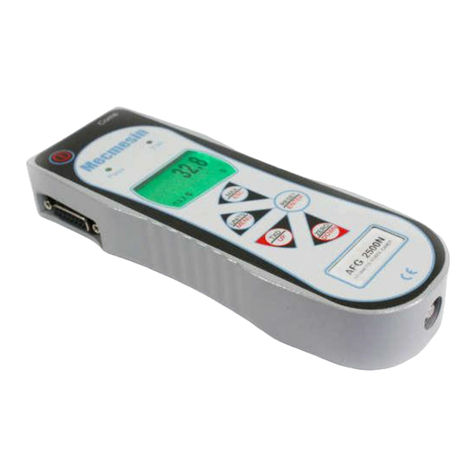
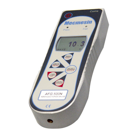
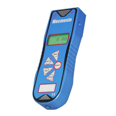
Mecmesin Compact Force Gauge User manual

F
orce
G
auge
Thank you for choosing this Mecmesin
instrument. With correct use it will give
many years of accurate and reliable
service.
Upon receiving the unit please check
that no physical damage has occurred
to the packaging material or the gauge
itself. If any damage is evident please
notify Mecmesin immediately.
When the low battery symbol appears
on the display, four new 1.5V AA
batteries should be fitted. Rechargeable
1.2V batteries should not be fitted to the
gauge. To release the battery cover at
the rear of the gauge press the battery
cover as indicated by the arrow and
slide the cover upwards. Ensure all
batteries are inserted the correct way
round. Incorrect insertion of batteries
can cause damage to the gauge. To
replace the battery cover slide it in from
the top edge of the gauge until it clicks
into place.
If the gauge is not going to be used for
3 months or more the batteries should
be removed and stored separately.
(Settings and calibration data will not
be lost if batteries are removed).
The gauge can be powered on by
pressing the large ‘ON/ZERO’ key.
After a short self test during which the
software version number and revision
date are shown, the gauge then
displays the transducers range before
entering the main display mode.
After the self test and providing no load
has been applied to the gauge, the
display will show zero, this is because
the gauge re-zeros itself as part of the
self test routine.
Fitting and
Replacing
Batteries
Powering Up
More than 120% of full scale load is
being applied to the transducer
‘-0L-’ Physical
overload
‘0L’ Maximum
reading overload
(not physical)
‘t-Err’ Tare error
‘No Ao’ No Auto
off
‘C-dEF’
Calibration default
Operating Instructions
Display Messages Before Use
Automatic power off is disabled
The zero function was performed
while the transducer was in an
overloaded state
The peak force reading was an
overload
DEALER STAMP
431- 051 - 02
Operating Manual
For a copy of the EC Declaration of Conformity please refer to:
www.mecmesin.com/literature/cedeclarations.html
Declaration of conformity supplied as standard, Calibration
certificate available on request
Force and Torque Test Solutions
Mecmesin Limited
Newton House
Spring Copse Business Park
Slinfold
West Sussex
RH13 0SZ
England
T +44 (0) 1403 799979
F +44 (0) 1403 799975
E [email protected]
www.mecmesin.com
F
orce
G
auge
C
ompact
C
ompact
Calibration data has become invalid
please notify Mecmesin or an authorised
representative for re-calibration
If the gauge is being used for a long test
the user may wish to disable the auto off
function. The auto off function can be
disabled when powering up the gauge
by holding down the ‘ON/ZERO’ key
until the display shows ‘No Ao’.
If the ‘LOW BATTERY’ symbol is
showing, the gauge will power off
unconditionally at intervals of one
minute regardless of above setting and
also regardless of any key presses.
The gauge may be re-powered but
will power off every one minute as
long as the ‘LOW BATTERY’ symbol
remains shown.
This feature has been designed into the
gauge to ensure the integrity of
displayed readings. When the low
battery symbol is showing, displayed
readings may not be reliable. When
this happens replace the old batteries
with new ones.
If the highest peak force was an
overload the display will show ‘OL’. If the
transducer is currently still overloaded
the display will show ‘-OL-’ (with dashes),
refer to display messages on the back
of this leaflet.
Pressing the ‘MAX’ key a second time will
now show the highest compressive load
detected along with the compression
symbol as described above.
Before carrying out a new test the gauge
must first be re-zeroed so that it is ready
to detect the next maximum (peak force).
Pressing the ‘ON/ZERO’ key will clear
both tension and compression maximum
readings then zero the display.
The transducer in the gauge is a delicate
mechanical device. Care should be
taken when using the gauge so as not
to overload the transducers as this will
cause IRREPARABLE DAMAGE.
In all display modes, forces greater than
120% of full scale will show an ‘-OL-’
symbol and the corresponding
compression or tension symbols on the
display. If the display shows ‘OL’ (without
dashes) in either of the two max modes,
the transducer is not currently in
overloaded state but has been
overloaded at least once since the last
ZERO operation. The gauge keeps a
record of all overloads applied. This
record can only be cleared by trained
Mecmesin staff or representatives.
When powered, the gauge constantly
keeps a record of time elapsed since
the last key press in order to decide
whether or not to power down
automatically. If this function is not
disabled and the low battery symbol is
not showing , the gauge will power
down after approximately five minutes.
Following the self test the display shows
the actual force that is being applied to
the gauge’s transducer. If a force is carefully
applied via the sensing probe, the reading
on the display will be seen to register
this applied force.
Tensile forces on the compact gauge
are displayed as positive numbers with
the symbol .Compressive forces are
displayed with negative numbers (a minus
sign appears to the left of the digits),
with the symbol .
During the operation of the gauge it is
often necessary to zero the display, for
instance if you have added a fixture
that you do not want to become part of
the measured reading. This is achieved
by pressing the ‘ON/ZERO’ key.
When the gauge is in the process of
zeroing itself a row of segments on the
top and bottom of the display will be
seen to alternately blink once, when
completed the display will read zero.
This function will not be performed if the
gauge is currently in overloaded state.
The gauge is capable of displaying
many different force units of measurement:
Newtons (N), kilo Newtons (kN), grammes
force (gf), kilogrammes force (kgf), ounces
force (ozf), and pounds force(lbf).
To change the display units press the
‘UNITS’ key, the newly selected units
will be shown at the bottom of the
display. Each successive press of this
key will select the next available units
until the gauge returns to the original.
The gauge detects and stores an
independent maximum (peak) force in
both tension and compression. By pressing
the ‘MAX’ key, the highest tensile load
detected will be displayed along with
the tension symbol as described above.
Force Conventions
& Symbols
Zeroing
Measurement Units
Max Readings
Overload &
Transducers
‘Auto Off’ Function
Low Battery
AC Power Adaptor
Stand Mounting
Plate
Accessories
Optional Extras
A 6V AC-DC power adaptor (Fitted with
a 1.3mm DC power plug with +6V DC
on the centre conductor), can be
plugged into the right hand side of the
gauge. Connecting an incorrect power
adaptor can cause damage to the gauge.
Enables the Compact Gauge to be
mounted to a Mecmesin Test Stand.
A wide range of fixtures are available.
Supplied with small test hook, compression
plate and extension rod
NOTE: Always use the extension rod to attach both the test hook, compression
plate or other fixtures. Only tighten fixtures finger tight - DO NOT OVERTIGHTEN
Other Mecmesin Measuring Instrument manuals

Mecmesin BFG 10 User manual

Mecmesin

Mecmesin BFG 10 User manual

Mecmesin Mecmesin AFI User manual

Mecmesin

Mecmesin Mecmesin AFI User manual

Mecmesin 172100 User manual

Mecmesin

Mecmesin 172100 User manual

Mecmesin afg 1000n User manual

Mecmesin

Mecmesin afg 1000n User manual

Mecmesin SL Series User manual

Mecmesin

Mecmesin SL Series User manual

Mecmesin AFTI Installation and operating manual

Mecmesin

Mecmesin AFTI Installation and operating manual

Mecmesin AFG Series User manual

Mecmesin

Mecmesin AFG Series User manual

Mecmesin CAPTEST Instruction manual

Mecmesin

Mecmesin CAPTEST Instruction manual

Mecmesin AFG Series User manual

Mecmesin

Mecmesin AFG Series User manual

Mecmesin AFG 2.5 User manual

Mecmesin

Mecmesin AFG 2.5 User manual

Popular Measuring Instrument manuals by other brands

Sony TC-366-4 Owner's instruction manual

Sony

Sony TC-366-4 Owner's instruction manual

GreenValley LiAir X3 user guide

GreenValley

GreenValley LiAir X3 user guide

Axelbant Expert-M MKS-83B Operation manual

Axelbant

Axelbant Expert-M MKS-83B Operation manual

Regin HR-S instructions

Regin

Regin HR-S instructions

Magnetrol Jupiter JM4 Safety manual

Magnetrol

Magnetrol Jupiter JM4 Safety manual

insize ISF-DF Series Operation manual

insize

insize ISF-DF Series Operation manual

Wavetek 4040D Operation manual

Wavetek

Wavetek 4040D Operation manual

Trotec BM31 quick start guide

Trotec

Trotec BM31 quick start guide

Extech Instruments MA130 user manual

Extech Instruments

Extech Instruments MA130 user manual

Hanna Instruments HI 8014 instruction manual

Hanna Instruments

Hanna Instruments HI 8014 instruction manual

Solinst 101B instructions

Solinst

Solinst 101B instructions

ProfiTap ProfiShark 10G Installation and configuration manual

ProfiTap

ProfiTap ProfiShark 10G Installation and configuration manual

Cobolt 06-01 Series owner's manual

Cobolt

Cobolt 06-01 Series owner's manual

TL Electronic TL-3524 user manual

TL Electronic

TL Electronic TL-3524 user manual

Hach TL2360 Basic user manual

Hach

Hach TL2360 Basic user manual

Solartron 1253A operating manual

Solartron

Solartron 1253A operating manual

Savant BT-058 user manual

Savant

Savant BT-058 user manual

THORLABS PM200 quick reference

THORLABS

THORLABS PM200 quick reference

manuals.online logo
manuals.online logoBrands
  • About & Mission
  • Contact us
  • Privacy Policy
  • Terms and Conditions

Copyright 2025 Manuals.Online. All Rights Reserved.