Meco DT3150 User manual

DIGITAL
CLAMP
METER
MODEL : DT3150
INSTRUCTION
MANUAL
®
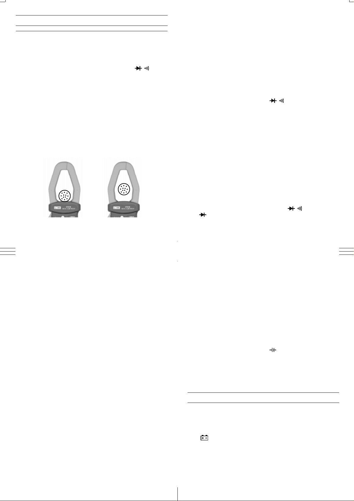
Bus-Barupto
16mm x 65mm
Cableupto
43mm Diameter
3 4
21
1. SPECIFICATIONS
1.1 General Specification
Display n3¾digit liquidcrystaldisplay(LCD)with a
maximumreadingof3999.
Polarity nAutomatic,positive implied,negativepolarity
indication.
Overrange n(OL) or (-OL) is displayed.
Zero nAutomatic.
Low battery n“ ” is displayed when the battery
indication voltage drops below the operating level.
Measurement n3 times per second, nominal.
rate
Operating n0°C to 50°C at < 70% relative humidity.
Environment
Storage n-20°C to 60°C, 0 to 80% R.H. with battery
Temperature removed from meter.
Power nTwo 1.5V ‘AAA’ SizeBattery
Battery life n200hourstypical
Dimensions n247mm (H) X 76mm (W) X 39mm (D)
Weight n465 grams approx.
Accessories nOne pairof test leads,instruction manual,
1.5Vbatterys (installed), CarringCase,
Maximum Jaw nCanmeasure roundcablesupto 43mm
Opening dia & Flats (Bus Bar) 65mm x 16mm
DCVOLTAGE (Auto Ranging)
Ranges : 4V,40V,400V,1000V
Accuracy : ±(0.5% rdg + 4 dgt) on 4V
± (0.7% rdg + 4 dgt) on 40V & 400V
± (1% of rdg + 4 dgt) on 1000V
Resolution : 1mVto 1V
InputImpedance : 10MVon allrangesexcept,
11MVon 4V
OverloadProtection : 1200VDC/800VAC
AC VOLTAGE (Auto Ranging) 40-500Hz
Range : 4V, 40V, 400V,750V
Accuracy : ±(1.0% rdg + 8 dgt) on all ranges except,
± (1.5% rdg + 8 dgt) on 750V
Resolution : 1mVto 1V
InputImpedance : 10MVon allrangesexcept, 11MVon 4V
OverloadProtection : 1200VDC/800VAC
RESISTANCE (Auto Ranging)
Range : 400V, 4KV,40KV,400KV,4MV,40MV
Accuracy : ±(0.7% rdg + 4 dgt) on all ranges except
± (1.2% of rdg + 4 dgt) on 4MV
± (2.5% of rdg + 4 dgt) on 40MV
1.2 Electrical Specification
Accuracies are ± (% reading + number of digits) at 27 ± 5°C and
humidity of less than 75% RH.
AC CURRENT (50-60Hz)
Range Accuracy Overload Protection
40A ±(3% + 4dgt) 1000AAC Max.
400A / 1000A ±(2% + 4dgt) for 1 minute
Resolution : 0.1Vto0.01MV
Test Current : 0.7mAon400V,0.1mAon4KV,
30µAon 40KV,4µAon400KV
OverloadProtection : 500VDC/AC
Continuity Check
ThresholdLevel : 40VApprox.
ResponseTime : 1mSec. Approx.
OpenCircuit Voltage : 0.4VApprox.
Indication : ‘ ’ is displayed on LCD and buzzer sounds
atcontinuity.
OverloadProtection : 500VDC /AC
Diode Test
Measurement Current : 1.0 ± 0.6 mA Approx.
Open Circuit Voltage : 0.4V Approx.
OverloadProtection : 500VDC /AC
Frequency (Auto Ranging)
Range : 10.00Hz,50.00Hz, 500.0Hz,5.000kHz,
50.00kHz, 500.0kHz
Accuracy : ± (0.5% rdg + 2 dgt)
Sensitivity : 3V
Overvoltage Protection: 200V DC or AC peak
% Duty Cycle (Auto Ranging)
Range : 1% to 90%
Accuracy : ± (0.5% rdg + 5 dgt)
Resolution : 0.1%
Overvoltage Protection: 200V DC or AC peak
Capacitance (Auto Ranging)
Range : 40nf,400nf, 4mf,40mf,100mf
Accuracy : ± (5% rdg + 10 dgt)
Resolution : 0.01nfto0.1mf
7 8
65
3. When the reading is lower than 400 counts, set the range
switch to the next lower range position. For maximum
accuracy, select the lowest range possible without over
rangingthe meter.
2.1 Current Measurements
1. Set the Function / Range switch to the highest 1000A AC
range.
2. Press the trigger to open transformer jaws, clamp onto one
conductor only and release trigger. Jaws should be completely
closed. Read the current directly on the display. It is
recommended that the conductor be placed at th e center of
the closed jaws for maximum accuracy (Fig. - 1).
Fig.1
73
2.OPERATION
Before taking any measurements, read the safety information section.
Alwaysexamine the instrumentfordamage,contamination(excessive
dirt, grease, etc.) and defects. Examine the test leads for cracked or
frayedinsulation.Ifanyabnormalconditionsexistdonotattempttomake
anymeasurements.
SELECT BUTTON
InACVRangeitwillselectACV /Hz/Dutyfunction.InV/ /range it
willselectresistance or diodeor countinuity function. InHz it willselect
Hz/Dutyfunction.
DATA HOLD BUTTON
Press Data Hold button to toggle in and out of Data Hold mode, In the
Data Hold mode, the “ H ” annunciator is displayed.
2.2 Voltage Measurements
1. Connect the red test lead to the “VV” jack and the black test lead
to the “COM” jack.
2. Set the Function/Range switch to the desired Voltage type
(AC or DC)
3. Connect the test leads to the device or circuit being measured.
4. For DC, a (-) sign is displayed for negative polarity; positive
polarityis implied.
2.3 Resistance Measurements
1. Connect red test lead to the “VV” jack and black test lead
to the “COM” jack.
2. Setfunction /Range switch toV/ /position.
3. If the resistance being measured is connected to a circuit,
turn off power to the circuit being tested and discharge all
capacitors.
4. Connect test leads across the resistance being measured.
When measuring high resistance, be sure not to contact
adjacent points even if insulated because some insulators
have a relatively low insulation resistance, causing the measured
resistance to be lower than the actual resistance.
5. Read resistance value on digital display. If a high resistance
vaiue is shunted by a large value of capacitance allow display to
stabilize.
2.4 DiodeTest
1. Connect the red test lead to the “VV” jack and black test lead
to the “ COM ” jack.
2. Set the Function / Range switch to the V/ /position, select
“” by pressing select key.
3. Turn off power to the circuit under test.
4. Touch probes to the diode. A forward-voltage drop is about
0.6V(typical forasilicon diode).
5. If the digital display reads overrange “ OL ”, reverse the lead
connections. The placement of the test leads when the forward
reading is displayed indicates the orientation of the diode. The
red lead is positive and the black lead is negative. If overrange
“ OL ” is displayed with both lead connections, the junction is
open. If a low reading (less than 1000) is obtained with both
lead connections, the junction is shorted internally or (if
junction is measured in a circuit) the junction is shunted by a
resistance less than 1KV. In the letter case the junction must
be disconnected from the circuit in order to verify its operartion.
2.5 Continuity Measurement
In continuity test, the beeper sounds continuously, if the
resistance is less than 40V.
2.6 Frequency & Duty Cycle Measurement
There are 2 positions for Frequency & Duty cycle measurements.
a) “Hz” position (Not for line frequency measurement.)
b)“ACV”position ( forline frequency measurement.)
2.6a“Hz” position (Not for line frequency measurement.)
Sensitivity : 3V
FrequencyRange : 10Hz to 500kHz
Duty Cycle : 1% to 90%
Overvoltage Protection : 200V DC or AC peak
1. Connect test lead to “Hz” and “COM” terminal.
2. Set rotary switch to “Hz” posotion.
3. Select Frequency or Duty cycle by pressing “Select” key.
4. Connect the test leads across the source or load under
measurement.
2.6b “ACV”position (For line frequency measurement.)
Sensitivity : 2V
FrequencyRange : 40Hz to 500Hz
Duty Cycle : 10% to 90%
OvervoltageProtection : 1000VDCor 750V ACpeak
1. Connect test lead to “VV” and “COM”terminal.
2. Set rotary switch to “ACV” posotion.
3. Select Frequency or Duty cycle by pressing “Select” key.
4. Connect the test leads across the source or load under
measurement.
2.7 Capacitance measurement
1.Set function/Range Switchto “ ” position
2. Short the leads of the capacitor to be tested togather to ensure
that there is no charge on the capacitor.
3. Insert the capcitor leads into the capacitor test socket.
4. Read thecapacitance value inthe display.
3. MAINTENANCE
WARNING
Remove test leads before changing battery or servicing.
BatteryReplacement
Power issupplied bytwo 1.5V‘AAA’sizebatteryor Equivalent.
The “ ” appears on the LCD display when replacement is needed.
Toreplace the battery,removethe screw from the batterycoverand lift
offthe batterycase. Removethe batterys& replecedwithnewbatterys.
https://www.instrukart.com/
Other Meco Measuring Instrument manuals


