Meco 3510PHW User manual
3510PHW : 28-09-2012
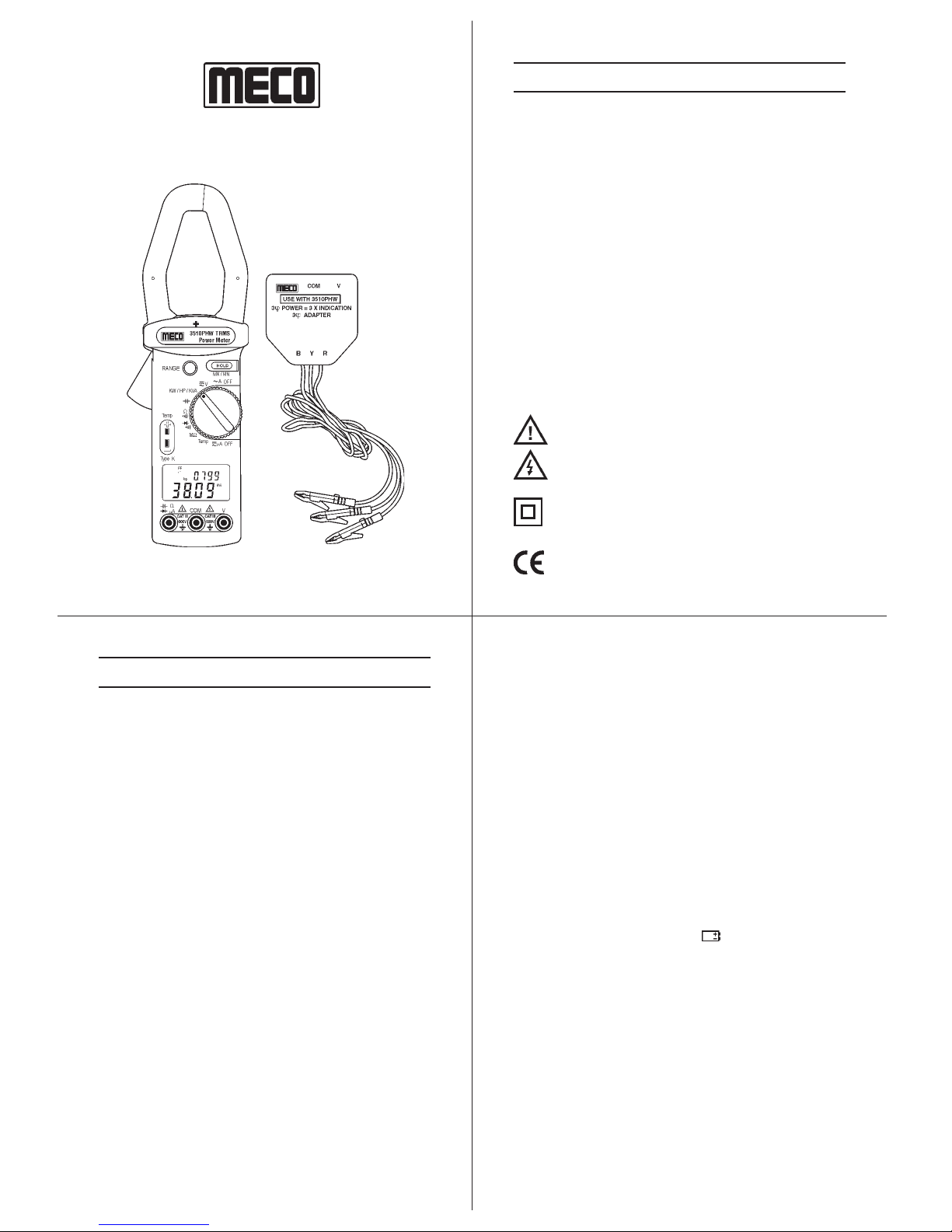
HVAC TRMS CLAMP METER
MODEL : 3510PHW
2
3 4
1
®
INSTRUCTION MANUAL
2.TECHNICALSPECIFICATIONS
2.1 Environment Conditions :
1. Installation category III
2. Pollutiondegree 2
3. Altitude up to 2000 meters
4. Indoor use only
5. Relatively humidity 80% max.
6. Operation ambient 0 ~ 50 0C
2.2 Maintenance :
1. Repairsorservicingisnotcovered in this manual, should
only be performed by qualified personnel.
2. Periodically wipe the case with a dry cloth. Do not use
abrasives or solvents on this instrument.
2.3 Features :
2.3-1 HVAC and Electrical :
1. To check current drawn by motors and compressors.
2. TouseMAX/MIN/Recordingin the temperature mode
to assess the efficiency.
3. To test run / start capacitors.
4. To measure low voltage control signals.
5. To measure flame protection diode current (<200mA)
in a heater control.
6. To analyze temperature and power data with the aid
of the time stamp.
7. Tomeasure highresistance.
8. To capture max. load current.
9. To determine peak power demand periods.
10. To monitor motors and other loads for excess heat.
1.SAFETY INFORMATION
lRead the following safety information carefully before
attempting to operate or service the meter.
lTo avoid damages to the instrument do not exceed the
maximum limits of the input values shown in the technical
specification tables.
lDo not use the meter or test leads if they look damaged.
lUseextremecautionwhenworkingaroundbareconductors
or bus bars. Accidental contact with the conductor could
result in electric shock.
lUse the meter only as specified in this manual; otherwise,
the protection provided by the meter may be impaired.
lRead the operating instructions before use and follow all
safety information.
lCaution when working with voltages above 60VDC or
30VAC RMS. Such voltages cause a shock hazard.
lBeforetakingresistancemeasurementsor testing acoustic
continuity, disconnect circuit from main power supply and
all loads from circuit.
Safety symbols
Caution refer to this manual before using the meter.
Dangerousvoltages.
Meter is protected throughout by double insulation
or reinforced insulation.
When servicing, use only specified replacement
parts.
Complies with EN-61010-1, IEC 1010-2-32
2.3-2 Functions :
1. TrueRMS,ACV,ACA,KW,KVA.
2. 9999 countsdual display LCD with unitsign.
3. DualKW+hp,KW+P.F,KW+KVAR,KVA+ u,A+V
(5 types)
4. Temp. 0C/0F
5. Dual display A + Hz, V + Hz.
6. Dataholdmode/MAX-MINmode
7. Auto PowerOffand to disable AutoPoweroff
function.
2-4 General Specifications :
Maximum voltage between any terminal and earth ground :
600Vrms.
Numericaldualdisplay : Dualdisplay4digitLCD
maximumreading 9999.
(10,000CountReading)
Batterylife : approx.32hr
Lowbatteryindication : The “ ” is displayed when
thebatteryvoltage drops below
theoperatingvoltage.
Autopowerofftime : approx.30minutes.(To disable
AutoPower Off, please refer to
4-9)
Samplingrate : 2.5times / sec (Digital display)
1 times / 6 sec (on KW,KVA)
Jawopeningdiameter : CablesF43mm
Operatingtemperature : 00C to 500C (320F to 1220F)
andhumidity R.H. < 80%non-condensing.
Temperaturecoefficient : 0.1 x (specified accuracy) / 0C
(< 180C or > 280C, < 640F or >
820F)
Storagetemperature : - 100C to 600C (140F to 1400F)
andhumidity R.H. < 70%non-condensing.

3510PHW : 28-09-2012
6
7 8
5
AC Current : (50 to 400Hz) Trms
mATrms :(AC+DC)(Burden Voltage : 5mV/mA)(50to 400Hz)
2-5 Measurement Specifications :
Accuracy : ± (% of reading + number of digits) at 180C to
280C (640F to 820F) with relative humidity to 80%.
AC Voltage : (50 to 400Hz) Trms
Dimensions : 247 x 76 x 39 mm (approx.)
Weight : 465gmsincludingbattery
(approx.)
Accessories : Three phase adapter x 1,
Carrying Case x 1, Test leads
x 1, Battery (installed ) x 1, Pair
ofalligator clip x 1,Instruction
manual x 1
Range Resolution Accuracy Sensitivity Overload
Protection
99.99A 0.01A ±2% ±20dgts (50,60Hz) 0.10A 1000A
999.9A 0.1A ±4% ±20dgts (40-400Hz) 1.0A
Range Resolution Accuracy Sensitivity Overload
Protection
99.99mA 0.01mA±1% ±20dgts 0.20mA600V
999.9mA 0.1mA 2.0mA
Range Resolution Accuracy Sensitivity Overload
Protection
±1% ±20dgts (50,60Hz)
999.9mV 0.1mV ±2% ±20dgts (40-100Hz) 2.0mV
9.999V 0.001V 0.020V 600V
99.99V 0.01V ±1% ±20dgts (50,60Hz) 0.20V
600.0V 0.1V ±2% ±20dgts (40-400Hz) 2V
Input Impedance : 3MV
Resistance (Continuity <40Von the 999.9Vrange) :
Range Resolution Accuracy Overload
Protection
999.9V0.1V
9.999KV0.001KV±1% ±10dgts 600V
99.99KV0.01KV
999.9V0.1KV
MV:
Range Resolution Accuracy Overload
Protection
9.999MV0.001MV
99.99MV0.01MV±5% ±10dgts 600V
Capacitance :
Range Resolution Accuracy Overload
Protection
10.000mF 0.001mF
100.00mF 0.01mF ±1.5% ±5dgts 600V
1000.0mF 0.1mF
7000mF1mF ±2.5% ±15dgts
DCVoltage :
Range Resolution Accuracy Sensitivity Overload
Protection
999.9mV 0.1mV 2.0mV
9.999V 0.001V ±1% ±20dgts 0.020V 600V
99.99V 0.01V 0.20V
600.0V 0.1V 2V
Input Impedance : 3MV
PF & Phase Angle (50Hz, 60Hz) :
Range Resolution Accuracy Sensitivity
-600/ 00/ +6000.10±3.00ACV>100V, ACA>10A
-0.5 / 1 / +0.5
Frequency :
Range Resolution Accuracy Sensitivity
40Hz/1KHz 0.1Hz ±0.5%rdg ±2dgts ACV>1.2V,ACA>6A
Diode (Continuity<40mV) :
Range Resolution Accuracy Overload
Protection
2.000V 0.001V ±2% ±1dgts 600V
TRUE Power : (PF>0.5 or u<600) (1hp = 0.7457kW)
Range Resolution Accuracy Overload
Protection
60.00kW (<100A) 0.01kW ±5% +20 600VAC/
600.0kW (>100A) 0.1kW (50,60Hz) 1000AAC
Temperature (K-Type thermocouple) :
Range Resolution Accuracy Overload
Protection
-500C to 9000C 0.10C ±1% ±10C30VAC or60VDC
-580F to 10000F 0.10F ±1% ±20F
Horse Power : (PF>0.5 or u<600) (1hp = 0.7457kW)
Range Resolution Accuracy Overload
Protection
80.00HP (<100A) 0.01HP ±5% +20 600VAC/
800.0HP (>100A) 0.1HP (50,60Hz) 1000AAC
Apparent Power :
Range Resolution Accuracy Overload
Protection
60.00KVA
(<100A) 0.01KVA ±2.5%±20dgts 600VAC/1000AAC
600.0KVA 0.1KVA
(>100A)
3510PHW : 28-09-2012
10
11 12
9
4. OPERATINGINSTRUCTION
4.1 AC + DC Voltage Measurement
WARNING
Maximum inputis600V.Do notattempttotakeany
voltagemeasurementthatexceedstheselimits.
Exceeding theselimitscould causeelectricalshock
anddamagetotheclampmeter.
1. Set the rotary switchto the “ V ” position.
2. Insert the test leads in to the input jack. (Black to COM
and Red to V)
3. Connect the test leads in PARALLEL to the measured
circuit.
4. The meter will automatically switch to ACV or DCV
display.
5. The meter willautomaticallyselect theappropriaterange.
6. Read the voltage and frequency values displayed on
theLCD. NOTE
Thesensitivityforvoltagefrequencymeasurementis1.2V
and the frequency range is 40 - 1KHz. If the frequency is
less than 40Hz the LCD may show Hz.
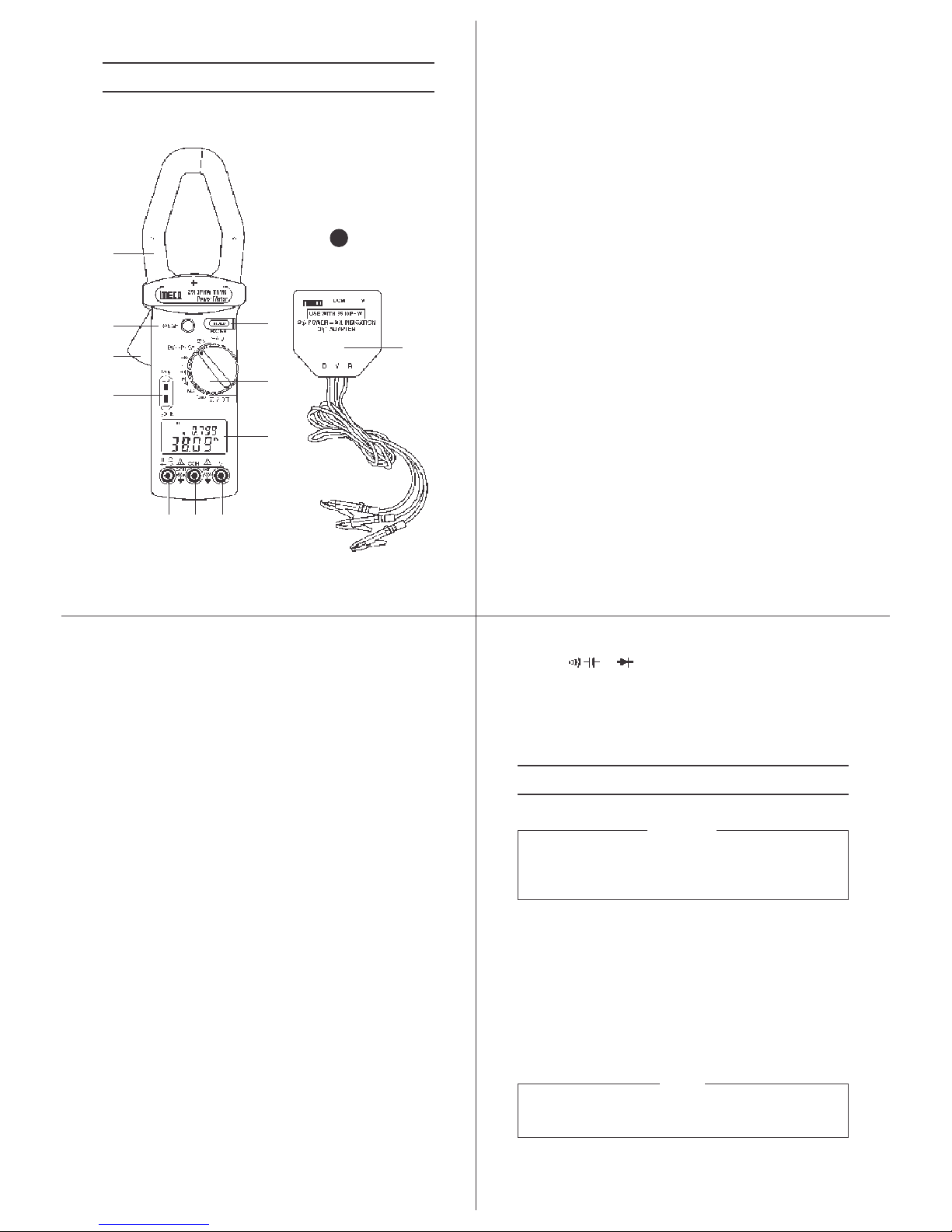
10. “ V mA ”Jack :
Connect red test lead for Capacitance, Resistance,
Diode, Countinuity and Micro ampere measurement
asa positiveterminal.
11. 3 Phase Adapter :
Insert plug in type 3 phase adapter in terminals
“COM”and“V”for3phase3wirepowermeasurement.
3. PARTS&CONTROLS
3.1 Description of Parts & Controls
2
5
4
10 8 9
3
7
6
1
11
Fig.
1
1. Transformerjaws(+marktofacesource):
TopickuptheACcurrentflowingthroughtheconductor.
2. Jawopeningtrigger
3. DataHold(MX/MN)button:
a. DataHoldMode:
Pressit once to hold the measured value and store the
value inmemory.Pressagaintoreleaseholdfunction.
(exceptcapacitancefunction)
b. MaximumandMinimumwithElapsedTimemode
0
1. Select desired ACA, ACV, DCV, C/ F or mA
function and perform the measurement, until the
measuredvalueshowsstablereadingontheLCD.
2. Press “ MX/MN ” button for 2 seconds to enter
recording with Elapsed Time mode, LCD will show
“ ® ” mark to lock the measurement range and
“ MX/MN ” mark to indicate the current measured
value with current elapsed time. The Auto Power
Offfunctionwillbeautomaticallycancelled.
3. Press “ MX/MN ” button one time, LCD will show
“ MX ” mark to indicate the recorded Maximum
valueandmaximumvalueoccurredElapsedTime.
4. Press “ MX/MN ” button one time, LCD will show
“MN ” marktoindicatetherecordedMinimum value
andminimumvalueoccurredElapsedTime.
5. Press “ MX/MN ” button one time, LCD will show
“ MX/MN ” mark to indicate the current value and
currentElapsedTime.
6. Step3,4,5canbecycled.
7. Press “ MX/MN ” button for 2 seconds to exit this
mode.
Note : The Elapsed Time intial setting is “ minute :
second ”, when current Elapsed Time is
over 60 minutes, the Elapsed Time will be
auto setting to “ hour : minute ”. The
maximum Elapsed Time length is 100
hours.
0
4. Functionselector:
Forselectionofdesiredfunction.
5. Rangebutton:
A. In ACA, ACV, DCV, mA, Capacitance and
Resistancefunction.
1. Press it once to enter the manual range select
mode,LCDwillshow®mark.
2. Pressagaintoselectthedesiredrange.
3. Press it 2 seconds to exit the manual range and
entertotheautorange mode, LCD ®markwill be
disappered.
B. InKW/HP/KVAfunction
a. Press RANGE button to select viewing the
KW/hp, KW/PF, KW/KVAR, KVA/uor V/A dual
display.
B1.Press HOLD button keep the measured valued
inmemory.
B2.Press RANGE button to select viewing the
KW/hp, KW/PF, KW/KVAR, KVA/uor V/A dual
display.
B3.PressHOLDbuttontoexitthismode.
C. InTEMPfunction 0 0
1. Press RANGE button to select desired C or F
temperatureunits.
6. Temperatureinputjack:
OnlytypeKthermocoupleinputisaccepted.
7. LCDDisplay:
4digital LCD with indicationsfor measurement values,
unit symbols, decimal point, polarity, over range and
lowbattery;etc.
8. COMJack:
Connect black test lead for voltage, Power,
Capacitance, Resistance, Diode, Countinuity and
Microamperemeasurement.
9. “V”Jack:
Connect red test lead for Voltage and Power
measurementasapositiveterminal.z
3510PHW : 28-09-2012
14
15 16
13
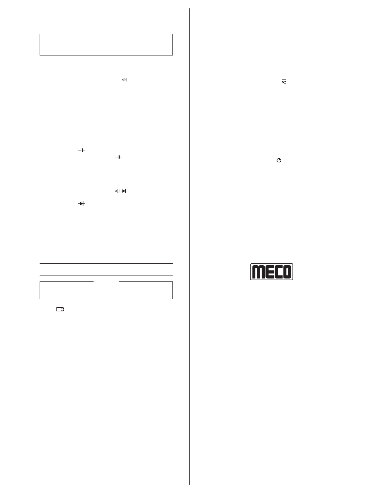
8. For 3 Phase 3 Wire balanced load system, insert 3f
plug in adapter in terminals “ COM ” and “ V ”. Connect
three crocodile clips to appropriate phase (R, Y and B).
Clamp “ R ” Phase conductor. 3f
power = 3 x Meter
indication (Refer fig 3).
9. For measurement in other systems please refer figures
4, 5 and 6.
NOTE
1. The “ + ” sign printed on panel must face the power
source for correct measurement.
2. If the device under test is switching mode power, the
meter KW, PF and
u
reading may be incorrect.
R
Y
B
N
Load
R
Y
B
N
Load
R
Y
B
N
Load
R
Y
B
N
Load
3f 4W Balanced System
Measured Value
= KW1, HP1, KVAR1 & KVA1
3f Values
= 3 x Displayed Value for
KW, HP, KVAR & KVA
Fig.
5
Fig.
6
Measured Value
= KW3, HP3, KVAR3 & KVA3
Measured Value
= KW2, HP2, KVAR2 & KVA2
3
f
Values = (KW1+KW2+KW3) or (HP1+HP2+HP3) or (KVAR1+KVAR2+KVAR3)
or (KVA1+KVA2+KVA3) 3
f
PF = KW
T
/
KW
T
+ KVAR
T
or KW
T
/
KVA
T
22
4.2 AC Current Measurement
1. Set the rotary switch to the “ A ” position.
2. Press the trigger to open the jaw and fully enclose the
conductor to be measured. No gap is allowed between
the two half jaws.
3. The clamp will automatically select the appropriate range.
4. Read the current and frequency values displayed on
the LCD.
NOTE
The sensitivity for Current frequency measurement is
6A and the frequency range is 40 ~ 400Hz. If the
frequency is less than 40Hz the LCD may show Hz.
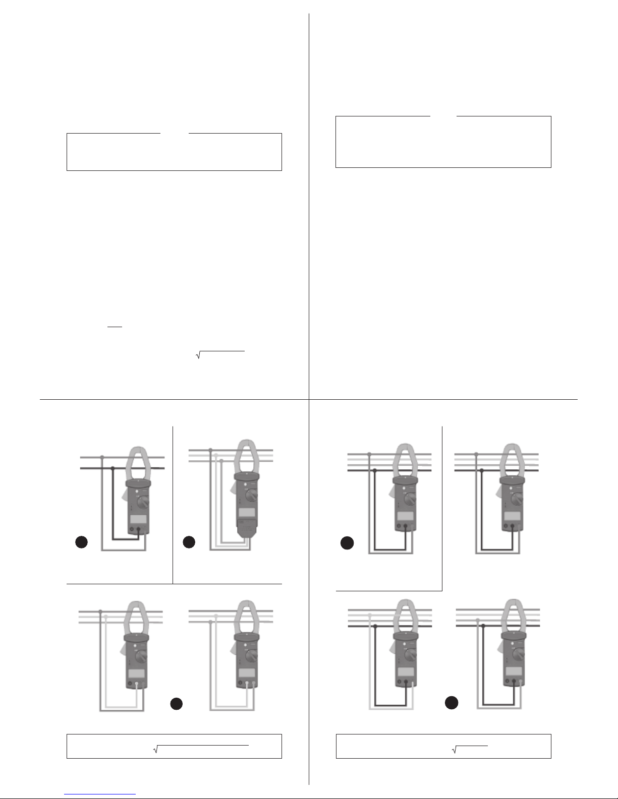
R
N
Load R
Y
B
Load
3f
Adapter
1f 2W System 3f 3W Balanced System
KW, HP, PF,f, KVAR, KVA
3f Values
= 3 x Displayed Value for
KW, HP, KVAR & KVA
Fig.
2
Fig.
3
R
Y
B
Load R
Y
B
Load
Measured Value
= KW1, HP1 & KVAR1
3f Values = (KW1+KW2) or (HP1+HP2) or (KVAR1+KVAR2)
3f PF = Cos[tan-1 3(KW1-KW2) /(KW1+KW2)]
Fig.
4
Measured Value
= KW2, HP2 & KVAR2
3f 3W Unbalanced System
3f4W Unbalanced System
4.3 AC Power KW, KVA, PF (Power Factor) and
uu
uu
u
(Phase
Angle) Measurement
1. Set the rotary switch to the “ KW/KVA ” position (refer to
figure 2).
2. Insert the test leads in to the input jack. (Black to COM
and Red to V)
3. Connect the Black lead COM to the neutral line.
4. Connect the Red lead V to the power line and clamp
the same conductor where V (red) terminal is connected.
5. The power clamp will automatically select the appropriate
range.
6. Read the watt and hp values displayed on the LCD.
7. Press range button to display required parameters.
PF = KW = COS
u
(
u
= Phase Angle)
KVA
KVA (Apparent Power) : KVA = (V*A)/1000
KVAR (Reactive Power) : KVAR = (KV-A)2-(KW)2=KVA*sin
u
HP (Horse Power) = 746W
3510PHW : 28-09-2012
18
19 20
17
CERTIFICATE OF CALIBRATION
Weherebycertifythatthisproducthasbeencalibrated
and found to be in accordance with the applicable
SPECIFICATIONS and MECO STANDARDS.
Accuracies of the standard equipment used in this
calibration are traceable to the National Standards.
MECO METERS PVT. LTD.
Plot No. EL-60, MIDC Electronic Zone,
TTC Industrial Area, Mahape,
Navi Mumbai - 400710 (INDIA)
Tel : 0091-22-27673311-16, 27673300 (Board)
Fax : 0091-22-27673310, 27673330
Web : www.mecoinst.com
SR. NO : __________________________
CHECKED BY : __________________________
DATE : __________________________
MODEL NO : __________________________
®
4.7 Temperature Measurement
1. Set the rotary switch to the “ Temp ” position.
2. Press RANGE button to select desired 0C or 0F
temperature units.
3. Insert the Type K thermocouple to the Temp jack.
4. Use temperature probe to touch the object being
measured and read the displayed value.
4.8 AC + DC Micro-Ampere Measurement
1. Set the rotary switch to the “ mA” position.
2. Insert the test leads into the input jack. (Black to COM
and Red to mA).
3. Connectthetestinserieswiththecircuitbeingmeasured
and read the displayed value.
4.9 To disable Auto Power Off function
The meter will automatically enter sleep mode if no button
is pressed and no function is changed for 30 minutes to
savepower consumption.
1. Set the rotary switch to the “ OFF ” position.
2. Pressandhold“HOLD ” key thensetthe rotary switch to
“~A ”Position,theautopoweroff functionwillbedisabled.
The auto power off mark “ ” will disappear.
Auto power off mode is enabled each time you turn on
the meter and is automatically disabled in the “MX / MN”
mode.
4. BATTERYREPLACEMENT
WARNING
To prevent electrical hazard or shock, turn off clamp meter
and disconnect test leads before removing back cover.
1. As battery power is not sufficient, LCD will display
“ ”. Replacement with one new battery type 9V is
required.
2. Set range switch to OFF position.
3. Use a screwdriver to unscrew the screw secured on
back cover. Take out the batteries and replace with one
newbatteryType9V.
4. Place back cover and secure with the screw.
4.4 Resistance & Continuity Measurement
WARNING
Beforetakingany in circuitresistance measurement,
removePower from the circuit being tested and
dischargeallcapacitors.
1. Before taking resistance measurement, make sure the
circuit is not live and discharge any capacitors present
in the circuit.
2. Set the rotary switch to the “ V, ” or “ MV ” range.
3. Insert the test leads into the input jack. (Black to COM
and Red to V).
4. Connect the test leads to the circuit being measured
and read the displayed value.
5. When the reading is below 40 V, it will be indicated by a
continuousbeeping.
4.5 Capacitance Measurement
1. Fully discharge the capacitor being tested, will speed
test response time.
2. Insert the test leads into the input jack. (Black to COM
and Red to ).
3. Set the rotary switch to the “ ” position.
4. Connect the red test leads to the positive side and black
testlead to thenegativesideofthe capacitor beingtested.
5. Read capacitancevalueon LCD.
4.6 Diode & Continuity Measurement
1. Set the rotary switch to the “ ” range.
2. Insert the test leads into the input jack. (Black to COM
and Red to ).
3. Connect the red test lead to the anode side and black
testleadto the cathode sideof the Diode beingtested.
4. When thereadingis below 40mV, itwillbe indicated by a
continousbeeping.
Table of contents
Other Meco Measuring Instrument manuals


