Meco 72-AUTO User manual
72-72T : 28-09-2012
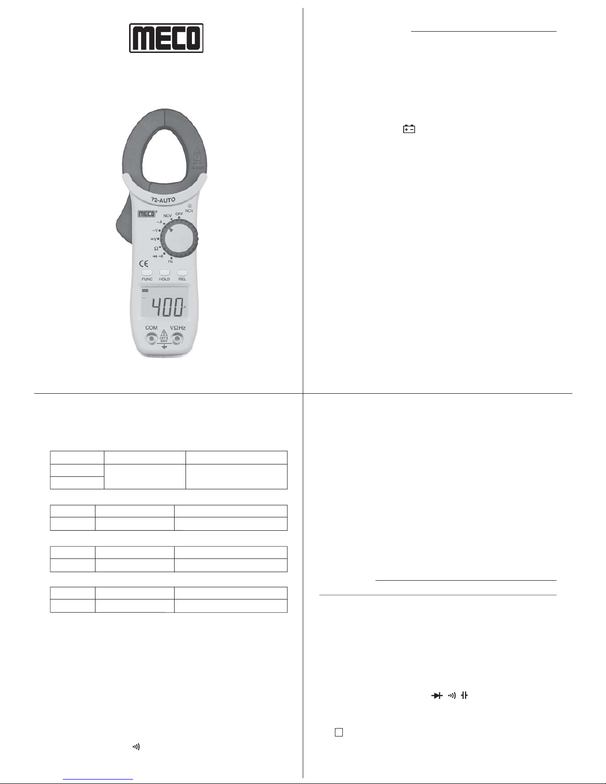
DIGITAL CLAMP METER
MODEL : 72-AUTO/72T-AUTO
INSTRUCTION MANUAL
®1. SPECIFICATIONS
1.1 General Specification
Display n3¾ digit liquid crystal display (LCD) with a
maximum reading of 4000 counts.
Polarity nAutomatic, positive implied, negative polarity
indication.
Overrange n(OL) or (-OL) is displayed.
Zero nAutomatic.
Low battery n“ ” is displayed when the battery
indication voltage drops below the operating level.
Measurement n3 times per second, nominal.
rate
Operating n0°C to 50°C at < 70% relative humidity.
Environment
Storage n-20°C to 60°C, 0 to 80% R.H. with battery
Temperature removed from meter.
Accuracy nStated accuracy at 270C ± 50C,
<75% relative humidity.
Power nTwo 1.5V ‘AAA’ Size Battery
Battery life n200 hours typical
Dimensions n185 x 65 x 28mm (approx.)
Weight n170gms including battery (approx.)
Accessories nPair of test leads x 1, Instruction manual x 1,
1.5V batterys (installed) x 2,
Carring Case x 1, (K type thermocouple upto
2600C for 72T-AUTO only) x 1
Maximum Jaw n25mm
Opening
1.2 Electrical Specification
Accuracies are ± (% reading + number of digits) at 27 ± 5°C and
humidity of less than 75% RH.
AC CURRENT (Auto Ranging) 50-60Hz
DC VOLTAGE (Auto Ranging)
Range Accuracy Overload Protection
600V ±(0.8% rdg + 3 dgt) 600V DC / AC rms
Range Accuracy Overload Protection
600V ±(1.2% rdg + 3 dgt) 600V DC / AC rms
RESISTANCE (Auto Ranging)
Range Accuracy Overload Protection
40MVV
VV
V±(1.2% rdg + 3 dgt) 250V DC / AC rms
AC VOLTAGE (Auto Ranging) 50-60Hz
Frequency (Auto Ranging)
Range : 10Hz, 100Hz, 1000Hz, 10KHz, 100KHz, 1000KHz, 10MHz
Accuracy : ± (0.5% rdg + 2 dgt)
Sensitivity : Approx 0.7V
Overload Protection : 250V DC / AC rms
Continuity Check
Threshold Level : 40VApprox.
Response Time : 1m Sec. Approx.
Open Circuit Voltage : 0.4V Approx.
Indication : ‘ ’ is displayed on LCD and buzzer sounds
at continuity.
3
21
Range Accuracy Overload Protection
40A ±(2.5% rdg + 5 dgt) 400A AC Max.
400A for 1 minute
Diode Test
Measurement Current : 1.0 ± 0.6 mA Approx.
Open Circuit Voltage : 1.6V Approx.
Capacitance (Auto Ranging) (72T-AUTO only)
Range : 5nF, 50nF, 500nF, 5mF, 50mF, 200mF.
Accuracy : ± (3% rdg + 2 dgts)
Overload Protection : 250V DC / AC rms
Temperature (72T-AUTO only)
Range : -200C to 7500C
Accuracy : ± (3% rdg + 5 dgts)
Resolution : 10C
Sensor : K type thermocouple
2. OPERATION
Before taking any measurements, read the safety information section.
Always examine the instrument for damage, contamination (excessive
dirt, grease, etc.) and defects. Examine the test leads for cracked or
frayed insulation. If any abnormal conditions exist do not attempt to
make any measurements.
AUTO POWER OFF (APO)
The meter will be switch off if no range switch or key is used for approx
15 minutes.
FUNCTION BUTTON
The Button is used for select V/ / / (72T-AUTO only) range.
HOLD BUTTON
Press Hold button to toggle in and out of Hold mode, In the Hold mode,
the “ H ” annunciator is displayed.
REL BUTTON
Press “REL” button to toggle in and out of “REL” mode. In this mode
72-72T : 28-09-2012 8
6
2.3 Resistance Measurements
1. Connect red test lead to the “VV” jack and black test lead
to the “COM” jack.
2. a) Set Range switch to the Vrange (72-AUTO)
b) Set Range switch to the V/ / / (72T-AUTO)
3. Select resistance range by using function button (72T-AUTO).
4. If the resistance being measured is connected to a circuit,
turn off power to the circuit being tested and discharge all
capacitors.
5. Connect test leads across the resistance being measured.
When measuring high resistance, be sure not to contact
adjacent points even if insulated because some insulators
have a relatively low insulation resistance, causing the measured
resistance to be lower than the actual resistance.
6. Read resistance value on digital display. If a high resistance
value is shunted by a large value of capacitance allow display to
stabilize.
2.4 Diode Test
1. Connect the red test lead to the “VV” jack and black test lead
to the “ COM ” jack.
2. a) Set the Range switch to the / (72-AUTO)
b) Set Range switch to the V/ / / (72T-AUTO)
3. Select Diode range by using Function Button.
4. Turn off power to the circuit under test.
5. Touch probes to the diode. A forward-voltage drop is about
0.6V (typical for a silicon diode).
6. If the digital display reads overrange “ OL ”, reverse the lead
connections. The placement of the test leads when the forward
reading is displayed indicates the orientation of the diode. The
red lead is positive and the black lead is negative. If overrange
“ OL ” is displayed with both lead connections, the junction is
open. If a low reading (less than 1000) is obtained with both
lead connections, the junction is shorted internally or (if
junction is measured in a circuit) the junction is shunted by a
resistance less than 1KV. In the letter case the junction must
be disconnected from the circuit in order to verify its operartion.
2.5 Continuity Measurement
1. Connect red test lead to the “VV” jack and black test lead
to the “COM” jack.
2. a) Set Range switch to the / (72-AUTO)
b) Set Range switch to the V/ / / (72T-AUTO)
3. Select Continuity range by using Function Button.
In the continuty test, the beeper sounds cuntinuously, if the
resistance is less than 40V.
2.6 NCV Check (ACV only)
Indicates presence of voltage in an electrical circuit or equipment
without touching them.
1. Set Range switch to the NCV Range.
2. The NCV indicator flashing every 1-2 sec.
3. When the clamp jaw near to the object under test it detected voltage.
The NCV LED is quickly flashing.
lDetection against inwall outlet is possible.
lIn NCV range meter will be auto power off within 3 minutes,
if no signals is obtained
2.7 Capacitance Measurment (72T-AUTO only)
1. Connect red test lead to the “VV” jack and black test lead
to the “COM” jack.
2. Set Range switch to the V/ / /
3. Select “” Range by using function button.
4. Turn off power to the circuit under test.
the “REL” annunciator is displayed and the respective range is active
only. This function is available for DCV, ACV, Current, Resistance &
Capacitance. In Capacitance “REL” acts as a “REL zero”.
NOTE : Use “REL” button to enter the relative mode, the “REL”
annunciator turn on, zero the display and store the displayed reading as
a referance value.
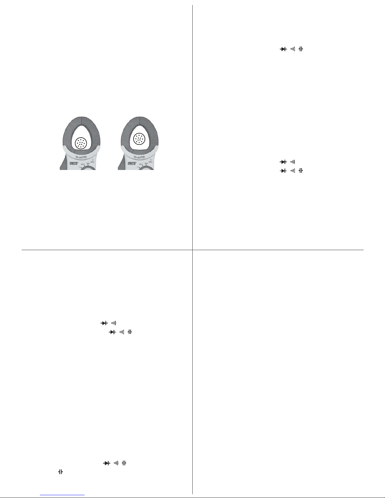
2.1 Current Measurements
1. Set the Range switch to the “A” range.
2. Press the trigger to open transformer jaws, clamp onto one
conductor only and release trigger. Jaws should be completely
closed. Read the current directly on the display. It is
recommended that the conductor be placed at th e center of
the closed jaws for maximum accuracy (Fig. - 1).
2.2 Voltage Measurements (AC or DC)
1. Connect the red test lead to the “VV” jack and the black test lead
to the “COM” jack.
2. Set the Range switch to the desired Voltage type (AC or DC)
3. Connect the test leads to the device or circuit being measured.
4. For DC, a (-) sign is displayed for negative polarity; positive
polarity is implied.
Fig. 1
73
5. By using “REL” button get zero display.
6. Connect the test leads to the capacitor and read the capacitance
directly from the display.
2.8 Frequency Measurment
1. Connect red test lead to the “VV” jack and black test lead
to the “COM” jack.
2. Set Range switch to the Hz
3. Connect the test leads to the points of measurment and read the
frequency from the display.
2.9 Temperature Measurment (72T-AUTO only)
1. Set range switch to 0C possition.
2. Connect the thermocouple “+, -” at VVand COM input terminals.
3. Touch the end of temperature probe to the area or surface of the
object whose temperature is to be measured.
Important : To avoid heat damage to the meter keep it away from
sources of very high temperature. The life of the temperature probe is
also reduced. When subjected to very high temperature.
5
72-72T : 28-09-2012
3. MAINTENANCE
WARNING : Remove test leads before changing battery or servicing.
Battery Replacement
Power is supplied by two 1.5V ‘AAA’ size battery or Equivalent.
The “ ” appears on the LCD display when replacement is needed, To
replace the battery, remove the screw from the battery cover and lift off
the battery cover. Remove the batterys & repleced with new batterys.
4. SAFETY INFORMATION
The following safety information must be observed to ensure maximum
personal safety during the operation of this meter:
1. Do not use the meter if the meter or test leads look damaged,
or if you suspect that the meter is not operating properly.
2. This Clamp Meter is designed to take current measurements
on circuits with a maximum voltage difference of 500VAC
between any conductor and ground potential. Using the
instrument for current measurements on circuits above this
voltage may cause electric shock, instrument damage or
damage to the equipment under test.
Before measuring current make certain the test leads are
removed from the instrument.
3. The instrument is protected for overload upto 600 VAC for 1
minute. Do not take current readings on circuits where the
maximum current potential is not known.
Do not exceed the maximum currents that this instrument is
designed to measure.
4. Turn off power to the circuit under test before cutting,
unsoldering, or breaking the circuit. Small amounts of current
can be dangerous.
5. Use caution when working above 60V DC or 30V AC rms.
Such voltages pose a shock hazard.
6. When using the probes, keep your fingers behind the finger
guards on the probes.
7. Measuring voltage which exceeds the limits of the clamp meter
may damage the meter and expose the operator to a shock
hazard. Always recognize the meter voltage limits as stated
on the front of the meter.
®
Certificate of Calibration
We hereby certify that this product has been calibrated and found
to be in accordance with the applicable SPECIFICATIONS and
STANDARDS.
Accuracies of the standard equipment used in this calibration
are traceable to the National Standards.
SR. NO. :
CHECKED BY :
DATE :
MODEL NO. :
MECO METERS PVT. LTD.
Plot No. EL-60, MIDC Electronic Zone, TTC Industrial Area,
Mahape, Navi Mumbai - 400710 (INDIA)
Tel : 0091-22-27673311-16, 27673300 (Board)
Fax : 0091-22-27673310, 27673330
Web : www.mecoinst.com
This manual suits for next models
1
Other Meco Measuring Instrument manuals


Popular Measuring Instrument manuals by other brands

Badger Meter
Badger Meter Primo Advanced BMAG-350-icpf Instruction and operation manual

Morehouse
Morehouse G501F instruction manual

Gill Instruments
Gill Instruments WindObserver II user manual

SSI
SSI Digital Fluid-Trac DFT-110 Application note

Stocks AG
Stocks AG MM 117A Installation, Calibration and Operation

Endress+Hauser
Endress+Hauser Cerabar PMC51B Brief operating instructions


