MED Associates NOLDUS SG-233 User manual

instrumentation and software for research
NOLDUS I/O INTERFACE
SG-233
USER’S MANUAL
DOC-238
Rev. 1.1
Copyright ©2014
All Rights Reserved
Med Associates Inc.
P.O. Box 319
St. Albans, Vermont 05478
Phone: 802.527.2343
Fax: 802.527.5095
www.med-associates.com

MED ASSOCIA T E S , I NC. SG- 23 3 I /O I N TE R F A CE
- i -
DOC-238 Rev 1.1 Copyright © 2014
Med Associates, Inc.
Table of Contents
Chapter 1 | Introduction ........................................................................................... 1
Specifications .................................................................................................... 1
Chapter 2 | Wiring Instructions ................................................................................. 2
Powering Other Devices Using the SG-233 ............................................................ 3
Chapter 3 | Changing the Output Configuration........................................................... 4
Appendix A | Contact Information .............................................................................. 5

MED ASSOCIA T E S , I NC. SG- 23 3 I /O I N TE R F A CE
- ii -
DOC-238 Rev 1.1 Copyright © 2014
Med Associates, Inc.
MED ASSOCIA T E S , I NC. SG- 23 3 I /O I N TE R F A CE
- 1 -
DOC-238 Rev 1.1 Copyright © 2014
Med Associates, Inc.
CHAPTER 1 | INTRODUCTION
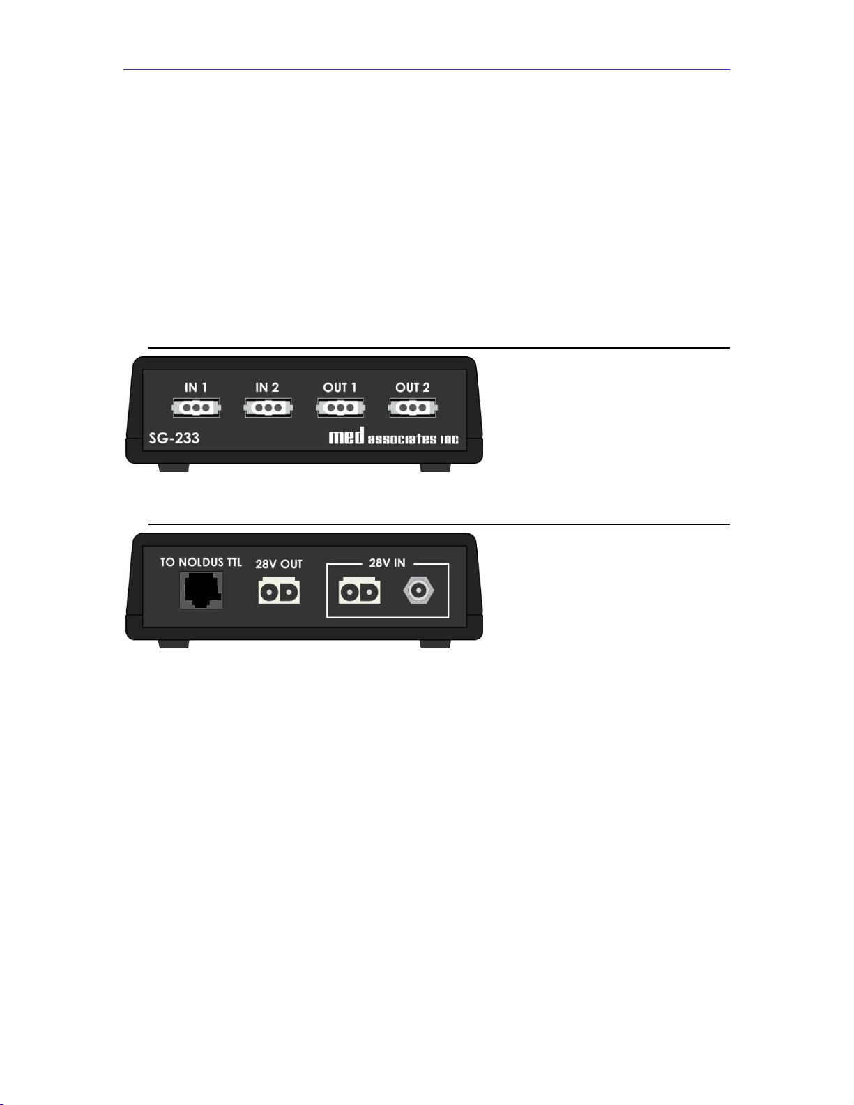
The SG-233 Noldus I/O Interface allows the interoperability of Med Associates Inc. and
Noldus Information Technology devices. The Interface provides two Med Associates
Standard 28V outputs and two Med Associates Standard 28V inputs, which are linked to a
Noldus standard RJ-45 connection.
The SG-233 may be powered by a Med Associates power supply (e.g. SG-501) via a two-
pin 28V Molex connection, or a 28V DC power supply (e.g. SG-508). A two-pin Molex 28V
output is also included to provide power to additional SG-233 or any other Med
Associates device using a daisy chain configuration.
Figure 1.1 - SG-233 Front Panel
Figure 2.2 - SG-233 Back Panel
Specifications
Power Requirements: 28V DC
Maximum Pass-through Current: 16 Amps
Dimensions: 5.1” L x 5.1” W x 1.5” H
MED ASSOCIA T E S , I NC. SG- 23 3 I /O I N TE R F A CE
- 2 -
DOC-238 Rev 1.1 Copyright © 2014
Med Associates, Inc.
CHAPTER 2 | WIRING INSTRUCTIONS
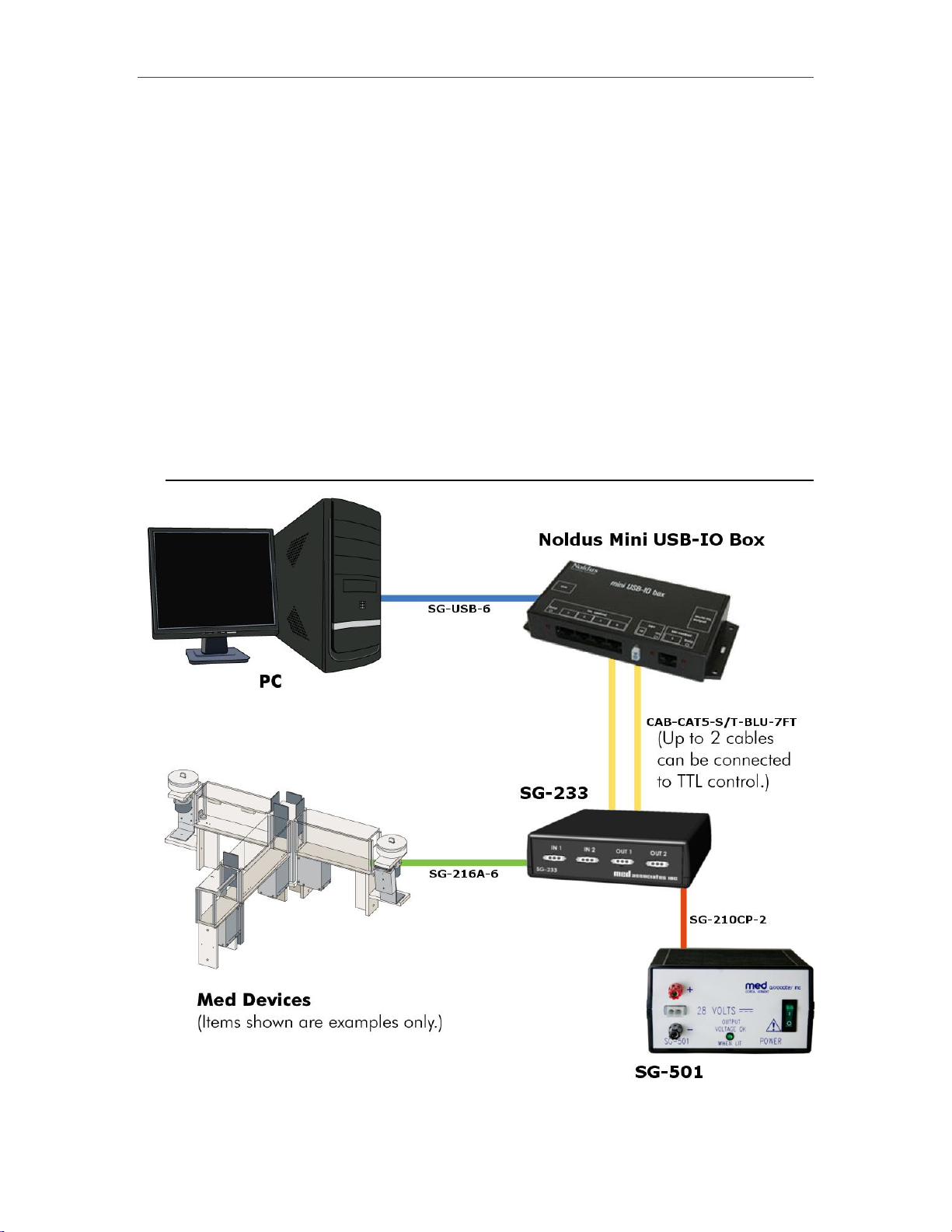
1. Connect a standard Ethernet cable from the connector labeled To Noldus TTL on the
SG-233 to any of the TTL control connectors on the front panel of the Noldus USB-
I/O Box.
2. Connect the IN1, IN2, OUT1 and OUT2 connectors on the SG-233 to desired Med
Associates devices. Figure 2.1 illustrates a typical wiring setup.
3. Apply power to the SG-233 in one of two ways:
a. Using a 28V DC power supply (e.g. SG-508), connect the 28V IN jack
input on the SG-233 to a standard wall outlet.
b. Using an SG-210CP 2-pin Molex cable, connect the 28V IN 2-pin Molex
connector on the SG-233 to a Med Associates Power Supply (e.g. SG-501).
4. Control the SG-233’s outputs or monitor its inputs using Noldus’ Ethovision XT
software.
Figure 2.1 - SG-233 Interface Wiring Diagram
MED ASSOCIA T E S , I NC. SG- 23 3 I /O I N TE R F A CE
- 3 -
DOC-238 Rev 1.1 Copyright © 2014
Med Associates, Inc.
Powering Other Devices Using the SG -233
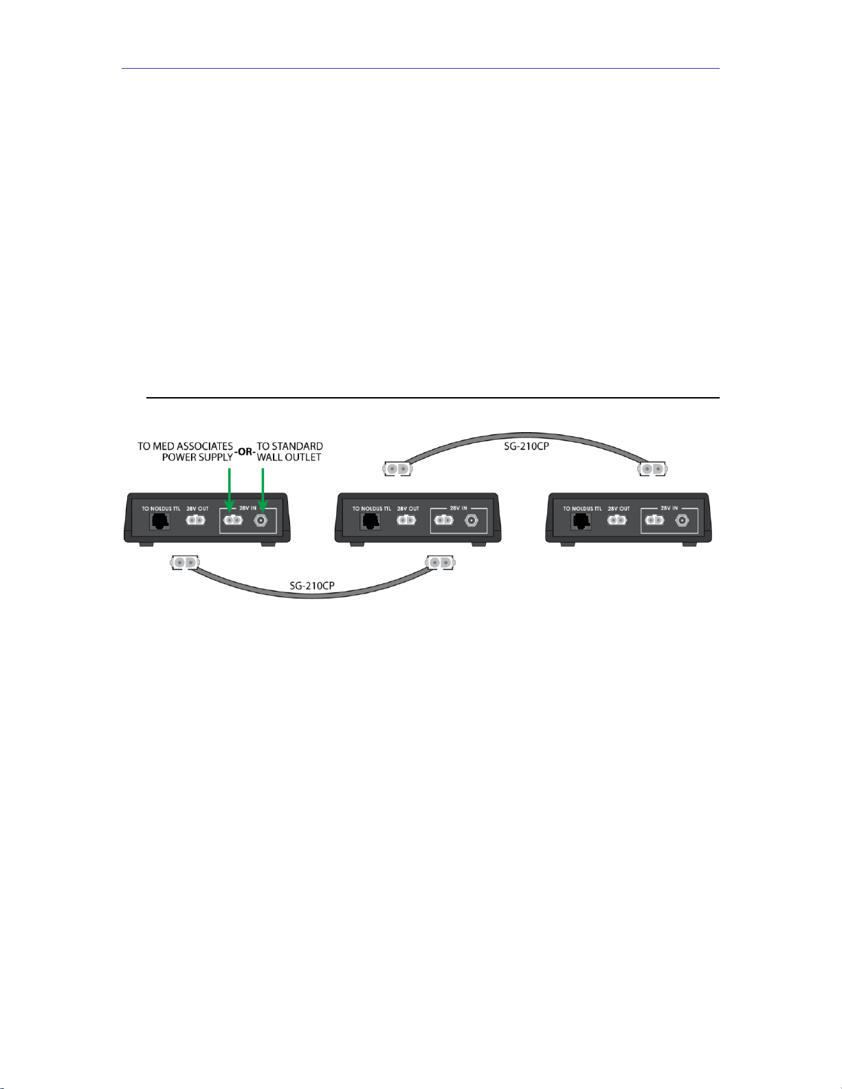
Additional Med Associates devices can be powered using the 28V OUT connector on the
SG-233, including multiple SG-233 interfaces.
Figure 2.2 illustrates three SG-233s that are daisy-chained, however the procedure is the
same for any Med Associates device. The procedure is described below:
1. Apply power to the SG-233 in either of the ways described in Step 3 of the Wiring
Instructions, above.
2. Using an SG-210CP, connect the 28V OUT connector on the SG-233 to the 28V IN
connector on the next Med Associates device.
Figure 2.2 –Daisy-Chaining SG-233 Interfaces
MED ASSOCIA T E S , I NC. SG- 23 3 I /O I N TE R F A CE
- 4 -
DOC-238 Rev 1.1 Copyright © 2014
Med Associates, Inc.
CHAPTER 3 | CHANGING THE OUTPUT CONFIGURATION
Most Med Associates equipment will activate when a “low” signal is received from an
output such as those on the SG-233. The outputs on the SG-233 can operate in one of
two ways, Normal or Invert mode. In Normal mode, an output of the SG-233 will be high
when the corresponding TTL port is set high, and the output will be low when the
corresponding TTL port is set low. In Invert mode, an output of the SG-233 will be high
when the corresponding TTL port is set low, and the output will be low when the
corresponding TTL port is set high. The output settings can be changed by adjusting the
position of dip switches inside the SG-233. The default setting is Normal mode.
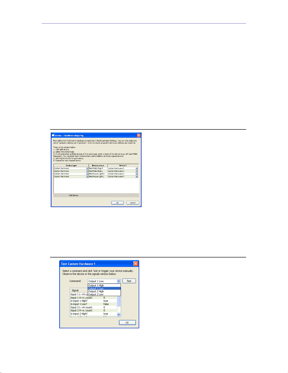
Med Associates equipment (custom hardware) is managed in the
Arena Settings
section
of Noldus’ Ethovision XT software. Figure 3.1 shows four custom hardware devices, two
Med Associates pellet dispensers and two Med Associates chamber house lights.
Figure 3.1 –Noldus Ethovision XT Arena Settings Custom Hardware Mapping
Figure 3.2 displays the custom hardware test screen. Each device can be tested for
functionality and “low” or “high” operability from this test screen prior to initiating an
experiment.
Figure 3.2 –Noldus Ethovision XT Arena Settings Custom Hardware Mapping

MED ASSOCIA T E S , I NC. SG- 23 3 I /O I N TE R F A CE
- 5 -
DOC-238 Rev 1.1 Copyright © 2014
Med Associates, Inc.
In order to change the outputs to invert mode, complete the following steps.
1. Disconnect all cables from the SG-233.
2. Turn the SG-233 over and remove the two screws from bottom of case; set aside.
3. Remove top of case by sliding it off in upward direction.
4. Locate header pins labeled J10 and J11. Jumper J10 corresponds to Output 1 on the
SG-233 and jumper J11 corresponds to Output 2.
5. To place an output in Normal mode, place the jumper across Pins 2 and 3, as shown
in Figure 3.3. This is the default jumper position.
Figure 3.3 - Jumpers J10 and J11 in Normal Mode
6. To place an output in Invert mode, place the jumper a cross Pins 1 and 2, as shown in
Figure 3.4.
Figure 3.4 - Jumpers J10 and J11 in Invert Mode
7. When done, replace top cover and secure the screws.
APPENDIX A | CONTACT INFORMATION
Please contact Med Associates, Inc. for information regarding any of our products.
Visit our website at www.med-associates.com for contact information.
For technical questions, email support@med-associates.com.
Table of contents
Other MED Associates Recording Equipment manuals


