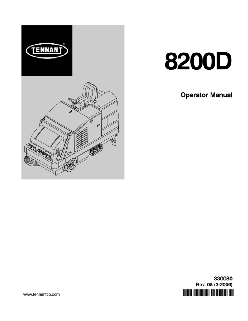
Media 22E-24E User manual

USE AND MAINTENANCE MANUAL
MEDIA 22E-24E
ED. 07-2010 EN
Doc. 10025342
Ver. AB

Le descrizioni contenute nella presente pubblicazione non si intendono impegnative.
L’azienda pertanto, si riserva il diritto di apportare in qualunque momento, le eventuali
modifiche ad organi, dettagli, forniture di accessori, che essa ritiene convenienti per un
miglioramento o per qualsiasi esigenza di carattere costruttivo o commerciale.
La riproduzione anche parziale dei testi e dei disegni, contenuti nella presente
pubblicazione, è vietata ai sensi di legge.
L’azienda si riserva il diritto di apportare modifiche di carattere tecnico e/o di dotazione. Le
immagini sono da intendersi di puro riferimento e non vincolanti in termini di design e
dotazione.
Simbologia utilizzata nel manuale
Simbolo del libro aperto con la i:
Indica che bisogna consultare le istruzioni per l’uso
Simbolo del libro aperto:
Indica all’operatore di leggere il manuale d’uso prima di utilizzare la
macchina
Simbolo di avvertimento
Leggere attentamente le sezioni precedute da questo simbolo, per la
sicurezza dell’operatore e della macchina
Simbolo di smaltimento
Leggere attentamente le sezioni precedute da questo simbolo, per lo
smaltimento della macchina

3
SUMMARY
ON CONSIGNMENT OF THE MACHINE....................................................................................................................4
INTRODUCTORY COMMENT.....................................................................................................................................4
TECHNICAL DATA......................................................................................................................................................4
SYMBOLOGY USED ON THE MACHINE...................................................................................................................5
SYMBOLOGY USED IN THE MANUAL......................................................................................................................7
MACHINE PREPARATION..........................................................................................................................................8
1. HANDLING OF THE PACKED MACHINE.............................................................................................................................8
2. HOW TO UNPACK THE MACHINE.......................................................................................................................................8
3. MAINS CONNECTION ..........................................................................................................................................................8
4. SQUEEGEE ASSEMBLY ......................................................................................................................................................9
5. ADJUSTMENT SQUEEGEE HEIGHT...................................................................................................................................9
6. ADJUSTMENT SQUEEGEE INCLINATION..........................................................................................................................9
7. ADJUSTMENT SQUEEGEE PRESSURE...........................................................................................................................10
8. SPLASH GUARD COVER...................................................................................................................................................10
9. BRUSH ASSEMBLY.............................................................................................................................................................10
10. RECOVERY TANK............................................................................................................................................................11
11. OUTER FILTER.................................................................................................................................................................11
12. SOLUTION WATER............................................................................................................................................................11
GENERAL RULES OF SECURITY............................................................................................................................12
PERFORMANCE........................................................................................................................................................13
SETTING FOR WORK .............................................................................................................................................................13
MOVEMENT ............................................................................................................................................................................14
BRAKE......................................................................................................................................................................................14
DEVICE TOO FULL .................................................................................................................................................................14
CIRCUIT BREAKER.................................................................................................................................................................15
BRUSH PRESSURE.................................................................................................................................................................15
ON COMPLETION OF THE WORK...........................................................................................................................16
DAILY MAINTENANCE .............................................................................................................................................17
CLEANING RECOVERY TANK ...............................................................................................................................................17
CLEANING SUCTION FILTER.................................................................................................................................................18
CLEANING SOLUTION FILTER...............................................................................................................................................18
CLEANING OF THE SQUEEGEE ............................................................................................................................................18
REPLACEMENT REAR SQUEEGEE RUBBER.......................................................................................................................18
REPLACEMENT FRONT SQUEEGEE RUBBER.....................................................................................................................19
DISASSEMBLY OF THE BRUSH ............................................................................................................................................19
WEEKLY MAINTENANCE.........................................................................................................................................20
CLEANING OF THE SQUEEGEE HOSE.................................................................................................................................20
CHECK BRAKE........................................................................................................................................................................20
TROUBLE SHOOTING GUIDE..................................................................................................................................21
INSUFFICIENT WATER ONTO THE BRUSH..........................................................................................................................21
THE MACHINE DOES NOT CLEAN SATISFACTORILY.........................................................................................................21
THE SQUEEGEE DOES NOT DRY PERFECTLY ...................................................................................................................21
EXCESSIVE FOAM PRODUCTION.........................................................................................................................................21
CHOICE AND USE OF BRUSHES............................................................................................................................22
EC DECLARATION OF CONFORMITY....................................................................................................................23

4
On consignment of the machine
When the machine is consigned to the customer, an
immediate check must be performed to ensure all the
material mentioned in the shipping documents have
been received and moreover to find out that the machine
has not suffered damage during transportation. If
damage has occurred, get the shipping agent to verify
immediately the amount and nature of the damage
suffered and at the same time inform our claim
department. It is only by prompt action of this type that
compensation for damage may be successfully claimed.
Introductory comment
This is a floor cleaning machine which, using the
mechanic abrasive action of a rotary brush and the
chemical action of a solution water-detergent, is able to
clean any type of floor, picking up during its advance
movement, the removed dirt and the detergent solution
which has not been absorbed from the floor.
The machine must be used only for such purpose.
We would impress upon you that any machine will
function efficiently and operate successfully, only if used
correctly and maintained in fully efficient working order.
We therefore suggest you to read this instruction booklet
carefully and re-read it whenever difficulties arise in the
course of machine use. Our Service Department is at
your disposal for all such advice and servicing as may
prove necessary.
MEDIA 22E MEDIA 24E
TECHNICAL DATA U.M. 10200041 10200045 11100041 11100045
Voltage/Frequency V/Hz 230/50 220/60 230/50 220/60
Cleaning width mm 540 540 610 610
Squeegee width mm 800 800 900 900
Working capacity, up to sqm/h 1890 1890 2135 2135
Brush diameter mm 540 540 610 610
Brush speed rpm 140 140 140 140
Brush pressure, up to kg 45 45 45 45
Power brush motor and traction W 750 750 750 750
Drive aut. aut. aut. aut.
Movement speed km/h 0÷3,5 0÷3,5 0÷3,5 0÷3,5
Max. gradient 10% 10% 10% 10%
Power suction motor W 550 550 550 550
Suction vacuum mbar 150 150 150 150
Solution tank l 60 60 80 80
Recovery tank l 70 70 85 85
Machine length mm 1420 1420 1500 1500
Machine height mm 1085 1085 1085 1085
Machine width (without squeegee) mm 590 590 650 650
Machine weight (empty) kg 126 126 140 140
Acoustic pressure level (conf. with EN dB (A) 70 70 <70 <70
Vibration level m/sqs 1,89 1,89 1,89 1,89
Input cable m 20 20 20 20

5
SYMBOLOGY USED ON THE MACHINE
0 / 1
Indicates the general switch
Indicates the warning light for the presence of the voltage
Symbol denoting cock
Indicates the cock lever
Indicates the solenoid valve switch
Symbol denoting up-down brush base
Indicates the lever of the brush base lifting
Symbol denoting brush
Indicates the switch of the brush motor
Symbol denoting suction motor
Indicates the switch of the suction motor
Symbol denoting up - down of the squeegee
Indicates the squeegee lever
Symbol denoting the reset of the safety switch
Symbol denoting brake
It is used on top of the emergency and parking brake lever

6
SYMBOLOGY USED ON THE MACHINE
Indicates the exhaust pipe of the recovery tank
Indication of the maximum temperature of the solution detergent
Placed near the charging hole of the solution tank
Symbol denoting the coupling
Indicates the anchor points and the load direction
Symbol denoting the open book
Indicates that, the operator has to read the manual before the use of the machine

7
SYMBOLOGY USED IN THE MANUAL
Symbol denoting a warning
Read carefully the sections preceded by this symbol, for the safety of the operator and of the
machine

8
MACHINE PREPARATION
1. HANDLING OF THE PACKED MACHINE
The machine is packed in a specific package provided on a pallet for the
handling with fork trucks. Do not place more than two packages on top of
each other. The total weight is 171 kg for Media22E and 185 kg for Media24E.
The overall dimensions are:
Media 22E Media 24E
A: 1280 mm A: 1280 mm
B: 760 mm B: 760 mm
C: 1520 mm C: 1520 mm
A
CB
2. HOW TO UNPACK THE MACHINE
1. Take off the outer package
2. The machine is fixed on the pallet with wooden wedges which block the
wheels and with metallic brackets
3. Take off the brackets and the wedges
4. Using a chute, get the machine down from the pallet, pushing it in reverse
motion. Avoid violent blows to the base and to the squeegee support
5. Keep the pallet for eventual transport necessities
3. MAINS CONNECTION
Before the working operation, check the tension and the frequency of the
electrical system, to which the machine has to be connected, paying attention
that, these ratings correspond to the data indicated on the machines' plate.

9
MACHINE PREPARATION
4. SQUEEGEE ASSEMBLY
The squeegee, which is packed separately from the machine, should be
assembled as shown in the figure. Insert first the left squeegee pin (1) in the
left arm slot, then the right pin (2) into the right slot, paying attention to keep
the spring and the washer over the blade of the arm itself. To simplify this
operation the handwheel placed on top of the pin should be loosened
previously. Afterwards, lock the handwheel to block the squeegee in position.
Fit the squeegee hose into its coupling (3) 2
3
1
5. ADJUSTMENT SQUEEGEE HEIGHT
The squeegee has to be regulated in height depending on the wearing of the
rubbers. To adjust this, rotate the knob (1) of each wheel clockwise to lift the
squeegee and counterclockwise to lower it.
Note: The right and left wheels must be adjusted at the same amount so that
the squeegee works in parallel to the floor.
6. ADJUSTMENT SQUEEGEE INCLINATION
During working operation, the rear rubber has to work slightly tilted backwards
and this equally in its whole length for about 5mm. Should it be necessary to
increase the rubber bending in the central part, tilt the squeegee body
backwards and turn the adjuster (1) counterclockwise. If the rubber bending is
to be noticeable at the sides of the squeegee, turn the adjuster clockwise. At
the end of the adjustment, block the adjuster nut.

10
MACHINE PREPARATION
7. ADJUSTMENT SQUEEGEE PRESSURE
The squeegee is already loaded with an appropriate pressure. It is possible to
adjust the squeegee pressure through the register (1) shown in the figure. In
order to increase pressure, it is necessary to tighten the register. To decrease
pressure, it is necessary to unscrew the register.
8. SPLASH GUARD COVER
The cover, which is packed separately, has to be assembled as shown in the
figure. Assemble the cover inserting it onto the arms, tighten the knobs (1)
with the washers.
1
9. BRUSH ASSEMBLY
1. Lift the brush base acting upon the lever (1)
2. Turn the key into position O. To carry out the operations of brush assembly
with connected current can cause damages to the hands.
3. Insert the brush placing it under the brush base, in correspondence of the
plate.
4. Lower the brush base, turn the key into position I, press the motor switch
(3), press the movable handle bar.
Now the brush is coupled.
ATTENTION! During this operation make sure that, there are not
any objects or persons close to the brush.
2
1
0I
3
5. Adjust, through the knob (1), the height of the splash guard rubber so that
it does not touch the floor.
The adjustment has to be repeated regularly depending on the brush wear
1

11
MACHINE PREPARATION
10. RECOVERY TANK
Open the cover (1) and check that, the suction connection (2) is properly
blocked by fitting the notches into its proper seat rotating it clockwise and that
it is connected regularly to the hose which goes to the suction motor.
Check furthermore that, the squeegee hose (3) is properly placed in their
seats and that the plug of the exhaust pipe, which is located in the rear part of
the machine, is closed.
2
3
11. OUTER FILTER
Check that the outer filter, placed between the cock and the solenoid valve, is
assembled correctly and that it is clean.
12. SOLUTION WATER
Fill the solution tank with clean water at a temperature of not more than 50°C
and add liquid detergent in the proper concentration following the instructions
of the manufacturer. Excess foam could damage the suction motor, so use
only the minimum amount of detergent necessary.
ATTENTION! Always use low foam detergent. To avoid the
production of foam, before starting to clean, put a minimum
quantity of antifoam liquid into the recovery tank. Never use pure
acid.

12
GENERAL RULES OF SECURITY
The rules below have to be followed carefully in order to avoid damages to the operator and to the
machine.
Read the labels carefully on the machine. Do not cover them for any reason and replace them immediately if
damaged
The machine must be used exclusively by authorized staff that has been instructed for its use
During the working of the machine, pay attention to other people and especially to the children
The socket for the power supply must be fitted with a standard earthing (ground) system
With the brush in working position, avoid touching or passing over the mains cable. Avoid damaging by
squashing, bending or stressing
Where there is damage to the mains cable, stop the machine, take off the plug from the mains system, and
replace the damaged cable immediately by calling the COMAC service department
Do not mix different detergents, avoiding harmful odours
Do not place any liquid containers onto the machine
The storage temperature has to be between -25°C and +55°C
The perfect operating temperature should be between 0°C and 40°C
The humidity should be between 30 and 95 %
Do not use the machine in explosive atmosphere
Do not use the machine as a means of transport
Do not use acid solutions which could damage the machine and/or the persons
Do not vacuum inflammable liquids
This appliance is not suitable for picking up hazardous dust
In case of fire, use a powder extinguisher. Do not use water
Do not strike shelvings or scaffoldings, where there is danger of falling objects
Adapt the utilization speed to the adhesion conditions
Do not use the machine on areas having a higher gradient than the one stated on the number plate
The machine has to carry out simultaneously the operations of washing and drying. Different operations have to
be carried out in areas which are not permitted for the passage of non employed staff. Signal the areas of moist
floors with suitable signs
If the machine does not work properly, check by conducting simple maintenance procedures. Otherwise, it is
better to ask for COMAC technical service.
Where parts are required, ask for ORIGINAL spare parts to an agent and/or to an authorized COMAC dealer
Use only original COMAC brushes indicated in the paragraph “CHOICE AND USE OF BRUSHES”
In case of danger act immediately upon the emergency brake
For any maintenance operation take off the power supply from the machine
Do not take off the pieces which require the use of tools to be removed
Do not wash the machine with direct water jets or with high water pressure nor with corrosive material
Every 200 working hours have a machine check through a COMAC service department
The machine should not be abandoned, because of the presence of materials subject to the rules which provide
for its recycling or scrapping in appropriate centres
In order to avoid scales on the solution tank filter, do not fill the detergent solution many hours before the
machines’ use
Before using the machine, check that all doors and coverings are in their position as indicated in this use and
maintenance catalogue
In conditions with unfavorable power supply, the apparatus can cause temporary voltage drops

13
PERFORMANCE
SETTING FOR WORK
1. Plug into the mains system
2. Turn the key of the general switch (1) into position I(clockwise).
Immediately, the signal lamp comes on (2)
2
1
0I
3. Press the motor switch (1)
4. Press the solenoid valve switch (2)
5. Press the suction motor switch (3)
3
21
6. Acting upon the cock lever (1) adjust the quantity of the detergent solution
which has to be sufficient to wet the floor uniformly but not too much to get
out of the splash guard. Please keep in mind that, the correct solution
quantity depends always on the type of floor, the dirt and the speed.
7. Release the lever (2) and lower the brush base
8. Lower the squeegee acting upon the lever (3)
9. Check that the parking brake (4) is released
10.Pushing downwards the drive lever (1), the machine begins to move.
During the first metres of operating, check that the quantity of detergent
solution is sufficient and that the squeegee dries perfectly.
The machine will now start working efficiently until the detergent solution
runs out.

14
PERFORMANCE
MOVEMENT
The traction of these machines is obtained through a flat belt put
into tension with the lever (1) as indicated in the figure. The
movement speed is proportional to the force carried on the lever.
ATTENTION! When carrying out even short backward
movements, make sure that the squeegee is lifted.
BRAKE
The machine is equipped with two braking systems. A working
brake controlled through the drive lever (1) and an emergency and
parking brake controlled through the lever (2). It is enough to
release the drive lever and the motor switches off.
Whenever problems during operating should arise, release the
drive lever and push immediately the emergency brake placed on
the left side. This command will block the traction of the machine.
To restart the machine again, once the problem has been solved,
release the lever of the parking brake and push downwards the
drive lever. 2
DEVICE TOO FULL
The machine is equipped with a float, which intervenes when the
recovery tank is full causing the closure of the suction hose.
It may be noticed, that the suction motor rises considerably its
revolutions. In that case, it is necessary to stop immediately the
suction motor and proceed with the emptying of the recovery tank
taking off the plug of the exhaust pipe.
ATTENTION! This operation has to be carried out
using gloves to protect from contact with dangerous
solutions.

15
PERFORMANCE
CIRCUIT BREAKER
The machine is equipped with a circuit breaker placed on the
instrument board which interrupts the current to the brush motor,
when it exceeds the predetermined load. In order to start up the
machine again, press the push button. If the circuit breaker
interrupts the current continuously, it is necessary to look for its
causes.
BRUSH PRESSURE
It is possible to adjust the brush pressure directly with the same
lifting lever. There are three predetermined positions. The highest
pressure is obtained when the lever is in the upper position.
The pressure must be chosen on the type of floor and the type of
dirt. Excessive pressure causes higher brushes wear and a major
energy consumption.
Approximately, these are the following loadings:
•position 1 brush on the floor 30 kg
•position 2 load at 31 kg
•position 3 load at 37 kg
•position 4 (to be used only with worn out brush) load at 45
kg
4
3
2
1

16
ON COMPLETION OF THE WORK
Having finished the job and before any type of maintenance is
done:
1. Close the cock through the lever (1)
2. Raise the brush base through the lever (2)
3. Raise the squeegee through the lever (3)
4. Switch off the solenoid valve switch (1)
5. Switch off the suction motor switch (3)
6. Switch off the switch of the general motor (2)
7. Turn the key (4) into position O(counterclockwise) and take if
off
8. Take off the plug from the mains system
9. Push the machine up to the place provided for the water outlet
10.Insert the parking brake
4
21
3
0I
11.Release the hose placed on the rear panel
12.Unscrew the exhaust plug and empty the tank
ATTENTION! This operation has to be carried out
using gloves to protect from contact with dangerous
solutions.
13.Take off the brush and clean it with a water jet (for the brush
disassembly please read further on under “DISASSEMBLY OF
THE BRUSH”)

17
DAILY MAINTENANCE
CLEANING RECOVERY TANK
1. Release the hose placed on the rear panel
2. Unscrew the exhaust plug and empty the tank completely
ATTENTION! This operation has to be carried out
using gloves to protect from contact with dangerous
solutions.
3. Lift the cover of the recovery tank
4. Take off the suction plug rotating it counterclockwise
5. Take off the filter and its protection
6. Rinse everything with a water jet. If a thorough cleaning should
be necessary, see under “CLEANING SUCTION FILTER”
7. Rinse thoroughly the inside of the tank
8. Reassemble everything

18
DAILY MAINTENANCE
CLEANING SUCTION FILTER
1. Lift the cover
2. Take off the suction plug by rotating it counterclockwise
3. Take off the filter with the antifoam protection
4. With a water jet clean the walls and the bottom of the filter
5. Wash thoroughly all components
Reassemble everything repeating above-mentioned operations inversely
CLEANING SOLUTION FILTER
1. Unscrew the cup
2. Take off the filter
3. Clean it thoroughly
4. Reassemble everything once again, tightening the cup to the filter body
CLEANING OF THE SQUEEGEE
In order to have the best drying results, check that the squeegee is always
clean.
To clean the squeegee it is necessary to:
1. Take off the hose (1) from the squeegee
2. Release the squeegee
3. Clean the inside of the squeegee thoroughly
4. Clean the squeegee rubbers thoroughly
5. Reassemble everything once more
REPLACEMENT REAR SQUEEGEE RUBBER
If the rear squeegee rubber is worn and does not dry well, it is possible to
change the drying edge proceeding as follows:
1. Push and rotate the fixing plates (1)
2. Slip off the rubber blade and the rubber itself
3. Turn the rubber (2) upside-down and if necessary, replace it
4. Reassemble everything repeating inversely above operations
5. Adjust the squeegee height depending on wear of the rubber (see under
“ADJUSTMENT SQUEEGEE HEIGHT”)

19
DAILY MAINTENANCE
REPLACEMENT FRONT SQUEEGEE RUBBER
If the front squeegee rubber is worn, a good suction is not achieved and
therefore the machine does not dry perfectly. In that case proceed as follows
with the replacement:
1. Take off the squeegee loosening the register (1)
2. Loosen the nuts which block the front rubber blade
3. Slip off the rubber blade
4. Slip off the rubber and replace it
Reassemble everything repeating inversely above operations
1
DISASSEMBLY OF THE BRUSH
The procedure of the operations of the brush disassembly is the following:
1. Lift the brush base acting upon the lever (1)
2. Brake the machine acting upon the lever (2)
3. Switch off the motor switch (3)
4. Turn the key into position 0 (4) and take off the plug from the mains
system
5. Get hold of the brush and with a sudden rotation clockwise, release it
from the couplings.
ATTENTION! This operation has to be carried out using gloves
to protect from contact with dangerous solutions 3
21
4
0I
In case of difficulties, it is possible to take off the plastic cover by unscrewing
the knobs (1) on the sides and pulling it forwards.
1

20
WEEKLY MAINTENANCE
CLEANING OF THE SQUEEGEE HOSE
Weekly or whenever suction seems to be unsatisfactory check that the
squeegee hose is not obstructed. Eventually, clean it proceeding as follows:
1. Take off the hose from its coupling on the squeegee
2. Take off the other end from the recovery tank
3. Wash the inner part of the hose with a water jet introduced from the side
where it is being connected to the tank
4. To reassemble the hose repeat the above-mentioned operations
inversely
ATTENTION! Do not wash the hose, which goes from the
suction motor to the suction plug.
CHECK BRAKE
Once a week check the distance between the brake pads of the emergency
brake and the wheels. Eventually, adjust them through the nuts bringing
them back to a distance of 3mm in resting conditions.
Table of contents
Popular Floor Machine manuals by other brands

Nilfisk-Advance
Nilfisk-Advance BRV 900 Instructions for use
Clarke
Clarke Clean Track 12 manual
HAKO
HAKO Scrubmaster B310 R CL/TB 1020 instruction manual
CleanFreak
CleanFreak TPL-17-220-CE-HEAT-TCP Operator's manual
Prochem
Prochem Comanche CM2EC 10075300 operating instructions

Nilfisk-Advance
Nilfisk-Advance BA 600 Instructions for use

