Meditech 12.1 inch portable User manual


User’s Manual of Patient Monitor
1
Product Information
This manual applies to system of the workbench kind of model parameters monitor. This series
of products is basically the same style of the basic operation and interface, by the universal
buttons, knob definition. The model of the parameters slightly different configuration of the
functional configuration parameters, detailed see "model function" and chapters table the
detailed description of!
Apply the product model in the list below
12.1 inch portable
12.l inch slim type
7 inch portable
15 inch slim type
Model function of comparisons table:
Related parameters
project
12.1 inch
portable
15 inch
slim type
12.l inch
slim type
7 inch
portable
Function
parameters
configuration
ECG
√
√
√
√
TEMP(T1/T2)
√(T1/T2)
√(T1/T2)
√T1
√T1
RESP
√
√
√
√
NIBP
√
√
√
√
SpO2
√
√
√
√
PR
√
√
√
√
EtCO2
□
□
×
×
IBP(1/2)
(Optional)
□
□
×
×
Battery
√
√
√
√
Recorder
√
□
×
√
LED alarm
indicator
√
√
×
√
Remote
Control
√
√
√
×
Bracket
(Optional)
□W/D
√W/D
√W
□W/D
Networking
√
√
√
√
Model
describing
difference
Display size
12.1”
15”
12.1”
7”
Display
Resolution
800*600
1024*768
800*600
800*480
Battery size
11.1V/4.4Ah
11.1V/4.4Ah
11.1V/4.4Ah
14.8V/2.2Ah
LED Battery
indicator
Peculiar
Peculiar
Peculiar
Peculiar
Display
Interface
Standard
Standard
Standard
Peculiar
Touch screen
×
√
×
×
Standard:√ Optional:□ Don't support:× W:wall D:desktop

User’s Manual of Patient Monitor
2
Contents
Safety Instruction................................................................................... 4
Chapter 1 Introduction........................................................................... 5
Chapter 2 Installation .......................................................................... 13
Chapter 3 Systmes Menu.................................................................... 16
Chapter 4 Alarm Function.................................................................... 26
Chapter 5 Recorder............................................................................. 39
Chapter 6 Review…………………………………..………………….38
Chapter 7 System interface................................................................. 45
Chapter 8 ECG / RESP Monitor .......................................................... 52
Chapter 9 SpO2 Monitor...................................................................... 65
Chapter 10 NIBP Monitor .................................................................... 71
Chapter 11 Temperature monitor......................................................... 82
Chapter 12 CO2 Monitoring…………………………………………......84
Chapter 13 IBP Monitor....................................................................... 91
Chapter 14 Common Troubleshooting............................................... 103
Chapter 15 Specifications.................................................................. 105
Chapter 16 Instal Bracket ……………………………………………... 112

User’s Manual of Patient Monitor
3
Safety Instruction
Any operator must read the following text carefully before using the monitor. This text will tell
operator the operation steps. Incorrect operation may cause malfunction and danger that may
harm the monitors or persons. Any malfunction or harm to the persons or monitors is caused
by wrong operation that can be avoided absolutely if according to the instruction indicated in
this text, manufacturer would be not responsible for the safety, reliability and performance
assurance. The manufacturer would not support free maintenance to this kind of malfunctions.
1. To secure circuit work well and insure the ECG signal high quality, the monitor must be
grounded correctly.
2. Adult mode is forbidden to use to measure the blood pressure of kids, or it would cause
harm because of over inflation, and even could cause severe hurt to kids..
3. Using this monitor on the patient with serious hemorrhage tendency may cause local
hemorrhage; patients with sickle cell anemia should be cautiously used on. .
4. Blood pressure could not be measured on the limb that is in drip-feed and intubation or
blood pressure cuff must not be bound to the patient whose skin is damaged locally.
5. Continuous use of finger-nipped SpO2sensor would cause discomfort or pain, especially
for the patient with microcirculation barrier. Operator had better not nip the sensor on the
same finger over two hours.
6. Some special patients need to be taken more careful check on the part of SpO2 sensor
measuring. Do not nip the sensor to the edema or vulnerable tissues.

User’s Manual of Patient Monitor
4
Chapter 1 Introduction
Applicable scope
This series patient monitor be bsed to Detection of patients ECG/ HR、TEMP、
RESP、NIBP、SPO2、EtCO2 and IBP.
Different types of products related functional description:
Functio
n
Model
ECG/HR
TEMP(T1/T2)
RESP
NIBP/PR
SpO2/PR
EtCO2
IBP(I1/I2)
12.1 inch
portable
√
√
√
√
√
□
□
15 inch
slim type
√
√
√
√
√
□
□
12.l inch
slim type
√
√(T1)
√
√
√
—
—
7 inch
portable
√
√(T1)
√
√
√
—
—
1.1 Working conditions
Temperature
Working temperature :5℃~40℃
Humidity
Working humidity:≤85%
Atmospheric pressure
Working pressure :86kPa - 106kPa
Power supply :AC 100 -240V 50/60Hz
Fuse :F2A L 250V φ5×20 (Peculiar:12.1” + 7”+15”slim type)
Match fitness:output DC 15V 3.3A (Peculiar:12.1”slim type+15””slim type)
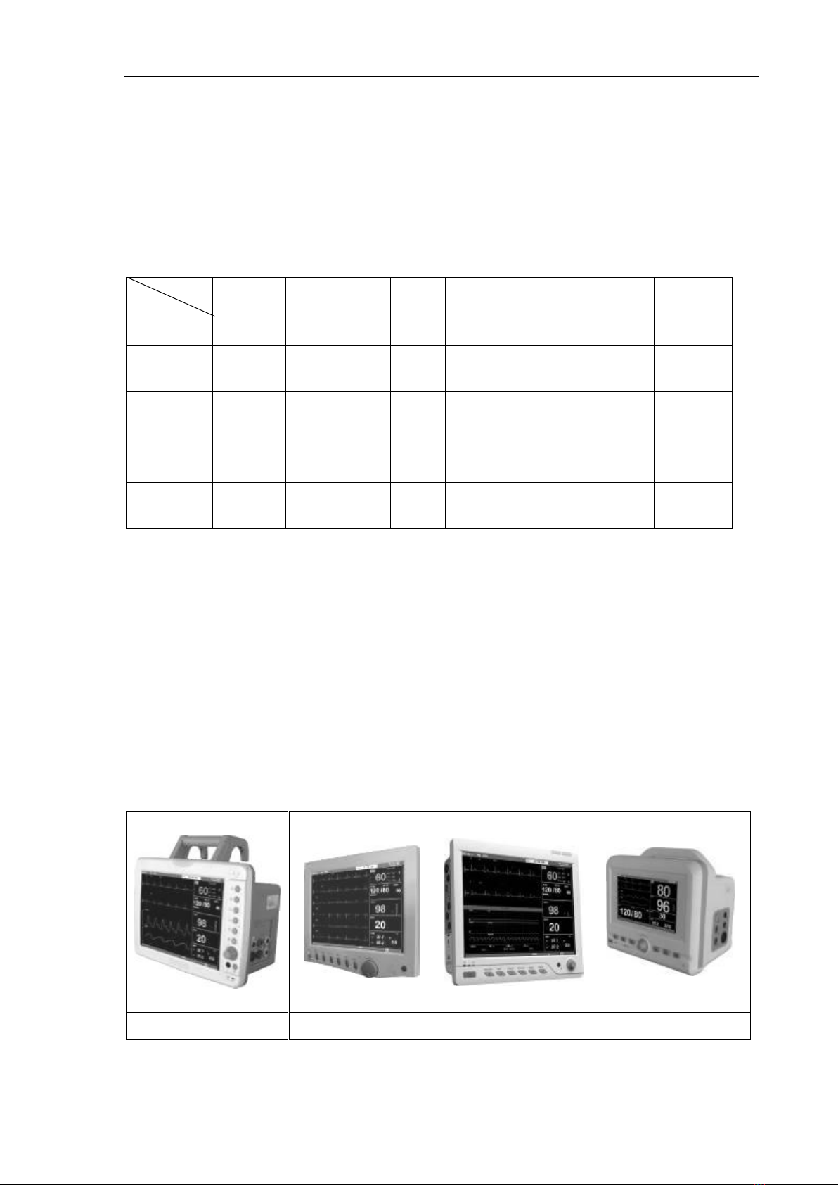
1.2 Exterior picture of the patient monitor
12.1” portable
12.1 slim type
15 slim type
7” portable
Multi-parameter patient monitor
1.2.1 Product control

User’s Manual of Patient Monitor
5

User’s Manual of Patient Monitor
6
(1) handle (2) independent lights (3) display (4) control view (5) shuttle key (6) front view
(7) back view (8) product nameplate (9) fan outlet (10) AC power switch (11) expansion
module fixed holes (12) AC input jack (13) fuse box (14) speakers (15) network interface
(16) grounding terminals (17) breaket fixed hole (18) recorder state indicator light (19)
recorder paper warehouse switch (20) recorder (21) battery warehouse cover (22) IBP2
interface (23) IBP1 interface (24) ECG interface (25) SpO2 interface (26) TEMP2 interface
(27) TEMP1 interface (28) EtCO2 interface (29) NIBP interface (30)AC indicator light (31)
DC indicator light (32) mute key (33) Alarm suspend key (34) frozen key (35) pressure
measuring key (36) print key (37) menu button (38) shuttle key (39) remote control knob
received through the window (40) system switch (41) battery status indicator (42) remote
control receiving indicator light (43) DC power socket (44) patient information area (45)
demo tip information area (46) technology alarm information area (47) physiological alarm
information area (48) system time instructions area (49) parameter information (50)
◆Because of the different product model and some module is optional
configuration, so you purchase the monitor may be not have certain functions or
the corresponding interface, please see the models of the corresponding
description.

User’s Manual of Patient Monitor
7
waveform instructions area display (51) tip information area (52)USB socket(53)Signal output
interface(54)Antenna interface
1.3 Control view
Control panel is located instrument on the board, the definition of detailed description
as follows.
(30)AC indicator light (31) DC indicator light (32) mute key (33) set key (34) frozen
key (35) pressure measuring key (36) print key (37) menu bu tton (38) shuttle key
(39) remote control knob received through the window (40) system switch (41) battery
status indicator (42) remote control receiving indicator light
●30——AC indicator light (join into alternating current power supply, indicating after power
supply switches on)
●31——DC indicator light (join into alternating current power supply, indicating when the system
works)
●32—— Silence: Press it to switch on/off alarm sound and other systems sound
●33—— Alarm suspend key: Alarm suspend key, can make the alarm suspended two
minutes (three optional Settings are "1 minute", "2 minutes" and "3 minutes").
●34—— Freeze: Press it to freeze the waveform to measure the ST segment.
●38——Shuttle key: Rotate it to choose menu item and change the setup. It can be rotated
deasil or widdershins, and pressed down. It can help finish all the operations on the
main screen, system menu and parameter menu. It can be used to move the basic
direction in the freezing status.
● 35—— Start: Press it to start to puff the cuff to measure the blood pressure. In the
procedure of measurement, press it to stop measurement and deflate; Press it every
time to start and stop the blood pressure measurement by turns.
● 36—— PRINT: Press it to print the current show.
● 37—— MENU: Press it to pop-up the frame of function menu.
● 40—— Soft switch on the power supply system: can be open monitor.
◆The product has many cabinet symbols, this symbol tips please be careful
operation, which see random material and product specifications in the description
and requirements.

User’s Manual of Patient Monitor
8
● 39—— remote control knob received through the window:Infrared remote control for
receiving a instructions.
●41—— battery status indicator:Used for the state of the storage battery charging and
discharging real-time instructions.
● 42——remote control receiving indicator light:Press the remote and accept to remote control
signal instructions.
Using Rotary knob to operate:
Cursor is moving when rotating the knob.The place where cursor located can be operated
accordingly.
When cursor is at the area of waveforms,users can modify current setting. When it is located at
parameter’s area, users can set information according to each parameter.
The operation are as follows:
◼Move cursor to items
◼Press the knob
◼Four conditions will occur
⚫It pops uo menu or measurewindow, or new menua replaced
⚫Cursor with color background truns to frame without color background
⚫Occur a “√” mark, which means choosing this item
1.4 Display of the screen
The screen is TFT colored LCD display with high resolution, which can show each parameter
and waveforms clearly. Other interface description:
(44) patient information area (45) demo tip information area (46) technology alarm
information area (47) physiological alarm information area (48) system time instructions area
(49) parameter information (50) waveform instructions area display (51) tip information
area
46---- Technology alarm information area
Show technical alarm information or indicating information, Report monitor’s screen
status. When without any information, it shows nothing
47---- Physiological alarm information area
Show physiologic alarm information, display circularly when one more information
48---- System time
Show current date and time
49---- Parameter information
Consisted of each small parameter area, it shows the measurement values according to
each parameter module. The upper left of each parameter is hot key. Through it, setting menu
for each parameter can be opened, for details, please refer to each parameter chapter. The
alarm information occurs regularly behind the area of each parameter. Showing menus
alarm is under off, and the sound of alarm is turned off until users cancel this operation. If

User’s Manual of Patient Monitor
9
without any display, it means this parameter is under alarm sound indication function.
50----Waveforms Area
It mainly shows waveforms of parameters, the left corner is the name of waveforms.
It shows 4 channels waveforms, the sequence of which can be adjusted. At most, it can
display 2 channels ECG waveforms, SPO2 pleth waveforms and RESP waveforms.
The name of waveforms is shown at the top left ECG lead can be chosen as requirement. It
also display gain and filter mode of ECG waveforms. There is a ruler about 1mv on the left side
of ECG waveforms. When pop up menu during operation, the menu always occupy the fixed
place on the middle of waveforms,so it make some part of waveforms invisible. Exit the menu
and return to previous menu.
The waveforms are renewed at the designed speed rate, please refer to each parameter’s
setting.
51----Indication Information
It display indicating information regarding to systems (demo,freezing),network mark, AC power
or battery symbol.
Audio symbol
It is alarm pause symbol. Press “Alarm” key (not exceeding 1 second) and occurs this
symbol, which means all of sound alarm having been off temporarily. It won’t recover sound
alarm unit “silence” key is pressed again or pause time is out. The time for pause is “1
minute” ,“2 minutes”,“3 minutes ”three kinds.
It is silence symbol, press it and occurs this symbol, which means the sound of alarm and
other system sound is turned off. It won’t recover until users press “silence” again for long time
to cancel silence status or systems happen new alarm event.
Alarm light and Alarm status:
On normal condition, alarm light won’t be on.When alarm happens, alarm light turns on or
glitters. The color of light stands for different class of alarm, details refer to alarm function.
Alarm information and indicating information, for more, please refer to regarding chapter.
◆12”Slim don’t have independent alarm function!
◆When the mark occurs, systems won’t carry out the alarm sound
function. Therefore, users should use this function carefully.

User’s Manual of Patient Monitor
10
1.5 Lithium battery
Configuration: various models of monitor of the corresponding lithium ion battery model see
the table below:
Model
Appearance
Battery
model
Battery
appearance
Specifications
Standby
time
12.1”
portable
TB0802
Li-ion Battery
11.1V /
4400mAh
≥2 hours
12.1”Slim
type
TB0802
Li-ion Battery
11.1V /
4400mAh
≥2 hours
15”Slim type
TB0901
Li-ion Battery
11.1V /
4400mAh
≥1hour
7” portable
TB0801
Li-ion Battery
14.8V /
2200mAh
≥1 hour
The patient monitor has option of built-in 11.1V or 14.8V Lithium ion battery. On the upper right
corner of the screen, there is a " " symbol, indicating the battery state, in which the green
part is the power of the battery. When the battery is full, the battery symbol will show " "
means the battery is full. When the monitor is not installed with built-in battery, the battery
status will show as " " means there is no battery.
With fully charged new battery the patient monitor can be used normally for two hour. When
being connected with AC power, the battery can be recharged automatically until it is fully
charged. The patient monitor will power off due to low power when using discharged battery.
Then the battery should be recharged by plugging intoAC power.
When using monitor on battery-power, regularly monitor and detect the battery power
insufficient warning prompted in the information area "less battery, please charge." AC power
should be connected at this time to charge the battery immediately.
When the battery needs to be changed, it is necessary to follow these steps: turn off the main
switch of power supply, plug out the power line, press the battery shell, and open the cover as
the direction indicated by the arrow mark. Please pay attention to the positive and negative
terminal of the recharged battery. Don’t connect contrarily.
Battery removing operations:
12.1”protable
Steps described
1. Cut down power supply, pull out of power supply line.
2. Invert monitor, open the bottom of battery case
3. Loose two screws by cross screwdrivers
4. Pour out the battery, pull out negative and positive poles of battery
5. Make sure the same model as previous battery, and then connect
the two poles of new battery
◆Pull out battery before deliver monitors, or don’t use it for long time!

User’s Manual of Patient Monitor
11
12”Slim type
Steps described
1. Cut down power supply, pull out of power supply line.
2. Reverse place host, remove the four host screws;
3. Flip host and open, carefully excision and pulled out relevant
connectors;
4. Pull out the output plug cable battery;
5. Cut open the fixed line firm, battery took battery and the line
pitcher;
6. Will new battery pack reposition the appropriate cable fixed
position;
7. Distinguish is negative, the plug into new battery pack original
position;
8. The relative connectors restore plug and examination;
9. turn on the power switch, the host should be able to normal boot
and into the system;
10. Turn off the power switch, to four host links side screws to fixed
lock;
11. Insert AC adapter, observe whether charging instructions and
normal power added;
15”Slim type
Steps described
1. Turn off the power, unplug the power cord;
2. using crosswise screwdriver unscrew the screw on the left side of
the battery compartment cover;
3. Remove the battery compartment cover and use thumb push up
the battery pack lock;
4. After battery is ejected, pinch the label on the battery pack, pulling
the battery pack off the battery compartment;
5. re-insert New battery pack to he battery compartment on right
direction, and lock automatically lock;
6. Cover the battery compartment lid and with a Phillips screwdriver
and screws to reconnect the host;
7. Turn on the power , the host should be able to start upt and into
the system, charging indicator should be normal;
8. Battery charging supplement;
7”portable
Steps described
1. Cut down power supply, pull out of power supply line.
2. Invert monitor, open the bottom of battery case
3. Loose two screws by cross screwdrivers
4. Pour out the battery, pull out negative and positive poles of battery
5. Make sure the same model as previous battery, and then connect
the two poles of new battery

User’s Manual of Patient Monitor
12
1.6 Remote controller specification:
1.Left key 2. Right key 3.Confirm key
4. Start key 5. Menu key 6.Silent key
7. Freezing key 8.Print key(optional) 9. Optional key (Not available now)
10. Infrared emitter 11.Battery position 12. Hole to hitch
13. Operation Identifier to open the battery door 14.Battery Model: CR 2025

User’s Manual of Patient Monitor
13
Chapter 2 Installation
◆Open the packing carton and check the accessories.
◆Connect the grounding end of the monitor.
◆Check input power supply and earthing.
◆Connect the sensor, cuff to the patient.
◆Turn on the On-OFF switch of main power supply and of monitor.
2.1 Open the carton and check
Take the patient monitor and the accessories out of the packing carton and keep the packing
material for the future transportation and storage. Please check the accessories:
◆Check whether there is any mechanical damage.
◆Check all the accessories and their links connecting plug-in units.
Please contact after-sale service department of our company or the dealer immediately in case
of any question.
2.2 Connecting AC power supply cable
Connect AC power supply as follows:
◆Make sure thatAC power supply comply with the standard:AC 100~240V 50/60Hz
◆Use power cable equipped with the patient monitor. Plug one terminal into the power
socket of the monitor while the other into the 3 pins of socket.
2.3Powering on
◆Connect the power cable to the special socket of the hospital.
After long transportation and storage, the battery should be recharged. Therefore, the
patient monitor can’t work normally without connecting to AC power supply possibly due
to low power of battery. By connectting with AC power supply, battery can be recharged
(whether the patient monitor is on or off). The fuse should be changed when it’s broken, the
model of fuse must be F2AL 250V Φ5×20.
◆Please read this chapter and the chapter of security of the patients before using the
patient monitor and install the monitor according to the requirement to ensure the patient
monitor works normally.
◆12’’ slim type monitor use the AC/DC adapter for power supply。

User’s Manual of Patient Monitor
14
①Standard configuration (without storage battery): check AC power supply cable. Turn on the
main switch of power supply on the rear side of the monitor, then the indicatior light will be
on, enter into the main screen of monitor after self-inspection of the system,then user can
operate it normally.
②Functional configuration of optional storage battery: check AC power supply cable, turn on
the main switch of power supply on the rear side of the monitor, then indicator “~” will be on.
After one second press the soft switch “ ” gently, the DC indicator will be on. When the
patient monitor displays the main monitor display after self-inspection, the user can operate
it normally.
Various models of monitor indicator light state and meaning please see table below:
battery status
indicator
green
flicker
battery abnormal
green
Always on
charging
No display
no
Has full
DC indicator
green
Always on
System work
No display
no
System does not work
remote control
light receiver‰
orange
flicker
Remote control receiver to
respond
red
Always on
Battery voltage low
AC indicator
green
Always on
AC input instructions
No display
no
Battery-powered or AC not
connected
battery status
indicator
green
flicker
charging
green
Always on
Has full
orange
flicker
Battery voltage low
orange
Always on
Battery discharge
No display
no
No built-in battery
AC indicator
green
Always on
AC input instructions
orange
flicker
Remote control receiver to
respond
battery status
indicator
green
flicker
charging
green
Always on
Has full
No display
no
No built-in battery
orange
Always on
Battery discharge
orange
flicker
Battery voltage low
DC indicator
green
Always on
System work
No display
no
System does not work
remote control
light receiver‰
orange
flicker
Remote control receiver to
respond
AC indicator
green
Always on
AC input instructions
No display
no
Battery-powered or AC not
connected
battery status
indicator
orange
Always on
charging
green
Always on
Has full
No display
no
No built-in battery
DC indicator
orange
Always on
Battery voltage low
green
Always on
Battery discharge
red
Always on
Abnormsl crlls or without
battery

User’s Manual of Patient Monitor
15
No display
no
AC power supply or battery
power
AC indicator
green
Always on
AC input instructions
No display
no
Battery-powered or AC not
connected
Connecting sensors
Connect the corresponding sensor to the patient monitor and the part of the patient.
◆Refer to the relative chapters for the ways of connecting all kinds of sensors and other
requirements.
◆If there is any damage in the monitor or indication of errors, please do not use it and
contact the after-sales service department of our company immediately.
◆Press the soft switch gently again for one second to swith off the system. If the
patient monitor is in the standby state for a long time, the user should turn off the main
switch of power supply and take the storage battery out of the monitor.
◆Check all the functions to make sure that the patient monitor works well.
If equipped with storage battery, battery should be recharged after each-time use to make
sure enough power storage.
◆The user should inspect and maintain the storage battery regularly to make sure the
battery works well.
◆After turnning off the device, wait for one minute to turn on the device again.

User’s Manual of Patient Monitor
16
Chapter 3 Systmes Menu
It introduces “Systems menu”, others will be clarified in following chapter
3.1 Patient information manage
3.2 Default
3.3 Recall
3.4 Monitor information
3.5 Monitor setup
3.6 Monitor maintenance
3.7 Drug calculation
3.8 Demo
This monitor is configurated flexibly. Users can set up the monitor information, speed rate of
scanning and so on. Press”menu” key on the front panel and pop up menu as follows:
3-1 Systems menu
3.1 Patient manage
Attention
◆Delect current patient data, please refer to “delete patient record ”
Select “Patient manage”in “System menu”, then pop up pic.3-2
3-2 Patient manage
Set up the following information by this menu:
◆Bed no. 1-200 optional

User’s Manual of Patient Monitor
17
◆Sex: Male or Female
◆Patient type: Adult, pediatric, neonate
◆Pace: on or off
◆New patient : receive new patient ,but not delect the previous data
In this menu, users can choose“new patient”to enter “Confirm to update patient”,as pic.3-3
3-3 Confirm to update patient
Select“Yes”,delete all data of currently monitored patient and exit the menu
Select“No”,continue to store the data, and exit the menu
Attention
If select “Yes”,it wil delect all data of currently monitored patient.
3.2 Default
Users can set current configuration as User default configuration.Then system will store all the
setting, like parameter, ECG Lead, gain and filter, as user default accordingly,and pop uo the
pic.3-4 window:
3-4 Default
Select “Yes”, store all current configuration as default
Select “No”, cancel current operation, system will still keep previous configuration
3.3 Recall
Select “Recall” in “System menu”,and then pop up pic.3-5 menu:
3-5 Recall menu

User’s Manual of Patient Monitor
18
There are “NIBP recall”,“Alarm recall”,“Trend Graph”,“Trend table”and so on, for more
details,please refer to Recall function.
3.4 Monitor Information
Select “Monitor information”in “System menu” to check the version information of monitor, like
pic.3-6 for reference, the actual content is accord to each monitor.
3-6 Monitor Versions
Select “Device Config list”to check the configuration of monitor, refer to pic.3-7
3-7 Device config list
3.5 Monitor setup
Select “Monitor setup” in “System menu” to pop up pic.3-8

User’s Manual of Patient Monitor
19
3-8 Monitor setup
The submenu available in this menu:
◆Face select: take reference to System menu
◆The alarm limit: open is the parameters that in next to the parameters that the alarm limit;
Close is the parameters in next to the parameter not display the alarm limit
◆Alarm record time: three choices: 8seconds, 16 seconds, 32 seconds .When alarm happens,
recorder will record and output it.
◆Key volume : four choices: “Off”, “Low”, “Middle”, “High” ,among of which “off” means
without any key volume
3.5.1 System Time
Select “time setup” in “monitor setup”, pop uo pic.3-9
3-9 time setup
Through rotary know, it can set up year, month, day, hour, minute and second.
Attention
◆System time should be set up when turning on monitor (If users need this setting),
otherwise it won’t show the correct time when recall.
3.5.2 Record output setting
Select “Record setup” in “Monitor setup”, pop up pic.3-10
This manual suits for next models
3
Table of contents