Medoc TSA 2001 Product manual
Proprietary 1 of 188
Small Fiber Test
Technical Reference
Manual
Q-Sense Technical Reference Manual
Proprietary 2 of 188
This User Manual contains proprietary information of Medoc Ltd. and may not be reproduced in
any form without prior written consent from Medoc Ltd.
DC 00076 Q-Sense Technical Reference Manual 12th Edition, Oct. 2018
Medoc Ltd.
1 Ha-Dekel St., PO Box 423 Ramat Yishai 3004627, ISRAEL
Tel.: +972-4-9038800 / Fax: +972-4-9038808
E-Mail [email protected]
www.medoc-web.com
Medoc U.S.A
Compass Medical Technologies, Inc.
1502 West Highway 54 - Suite 404
Durham, North Carolina, 27707, U.S.A
Tel.: +1-(919) 402-9600 / Fax: +1-(919) 402-9607
European Authorized Representative
CEpartner4U BV
Esdoornlaan 13 3951 DB Maarn, The Netherlands
Phone: +31 343 442.524 / Fax: +31 343 442 162
Mobile: +31 6 516 536.26
1282
This device complies with 93/42/EEC MDD

Q-Sense Technical Reference Manual
Proprietary 3 of 188
Table of Contents
1Safety Guidelines and Regulations ............................................. 14
1.1 User Manual Icons ....................................................................................... 14
1.2 Intended use................................................................................................ 15
1.3 Target Population and Contraindications ..................................................... 15
1.4 Safety and Regulatory Summary .................................................................. 15
1.5 Safety Requirements .................................................................................... 16
1.5.1 Warnings ................................................................................................. 16
1.5.2 Cautions .................................................................................................. 17
1.5.3 Equipment Classification ............................................................................ 18
1.6 System Protection ........................................................................................ 18
1.6.1 System Self-Test ...................................................................................... 18
1.6.2 Temperature Safety Mechanisms ................................................................ 18
1.6.3 Thermode Detection .................................................................................. 18
1.7 Equipment Labels, Symbols, Warning Statements and Abbreviations .......... 19
1.8 Electromagnetic immunity ........................................................................... 20
1.9 Recommended Separation Distance between Portable and Mobile RF
Communications Equipment and Q-Sense ............................................................. 24
1.10 Technical Data .......................................................................................... 25
2Overview .................................................................................... 27
2.1 Training........................................................................................................ 27
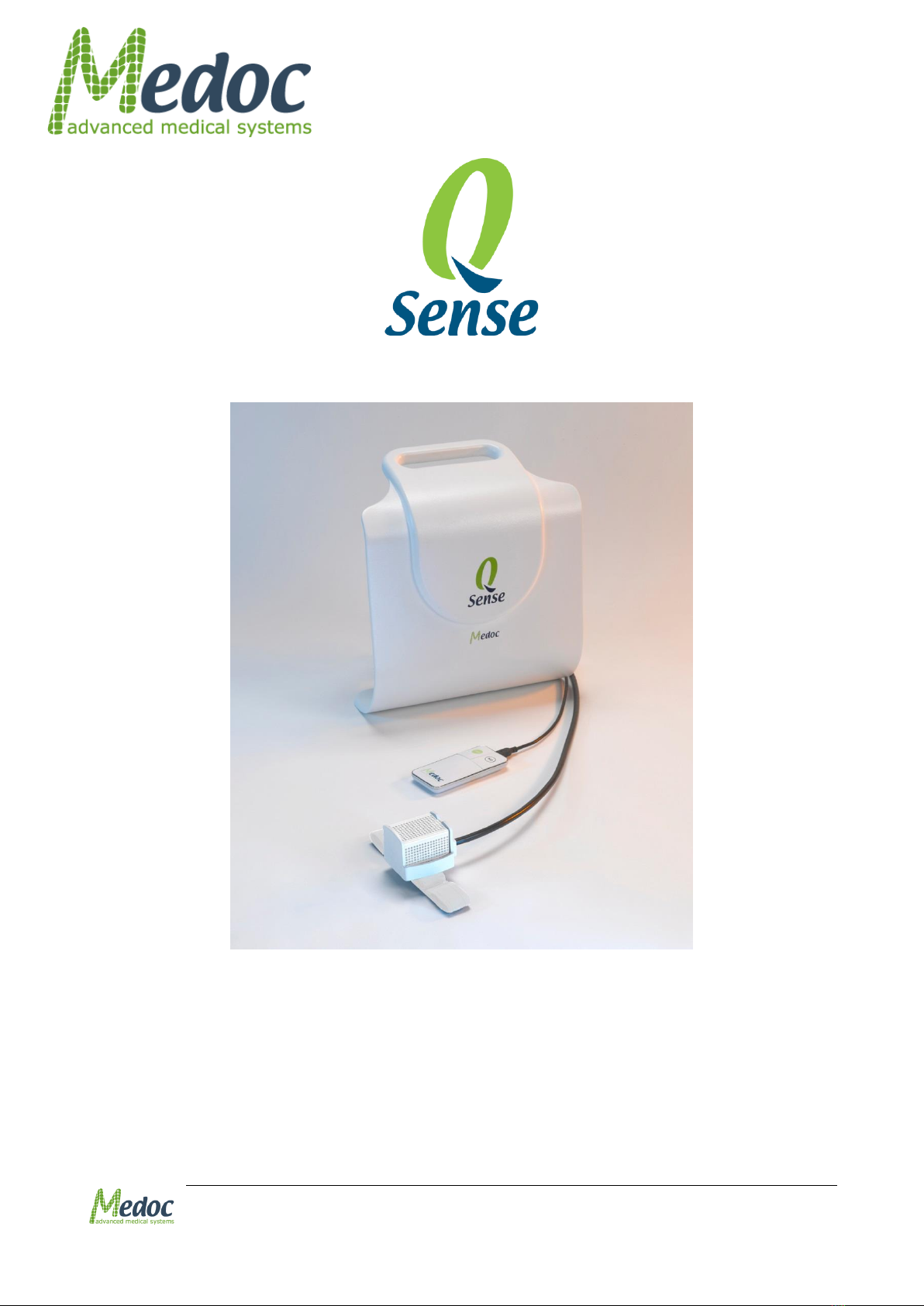
2.2 System Description ...................................................................................... 27
2.3 Q-SENSE Thermode ...................................................................................... 27
2.4 Terminology ................................................................................................. 27
2.5 System Status .............................................................................................. 28
2.6 System States .............................................................................................. 28
2.7 Application Methods..................................................................................... 29
2.7.1 Limits Method........................................................................................... 29
2.7.2 Levels Method .......................................................................................... 29
2.7.3 Thermal Sensory Limen (TSL)..................................................................... 29
2.7.4 Ramp & Hold Method ................................................................................. 30
2.7.5 VAS Search Method ................................................................................... 31
2.7.6 Chain Option ............................................................................................ 32
3System Components................................................................... 33
3.1 Power side Panel.......................................................................................... 33
3.2 Connectors side panel .................................................................................. 34
4Setup and Installation ................................................................ 36
4.1 Computer Requirements .............................................................................. 36

Q-Sense Technical Reference Manual
Proprietary 4 of 188
4.2 Installation USB Content .............................................................................. 37
4.3 Setup and Installation Main Steps................................................................ 37
4.4 Selecting a Location ..................................................................................... 37
4.5 Device Connections ...................................................................................... 38
4.6 Software Installation ................................................................................... 39
4.7 Unit Protection ............................................................................................. 40
4.8 Product Activation........................................................................................ 40
5Operation ................................................................................... 42
5.1 Power up Q-SENSE System........................................................................... 42
5.2 Starting Q-SENSE ......................................................................................... 42
5.3 System Self-Test .......................................................................................... 44
5.4 Basic Operation ............................................................................................ 45
5.4.1 Menu Bar ................................................................................................. 46
5.4.2 Toolbar .................................................................................................... 47
5.4.3 Search Row .............................................................................................. 47
5.4.4 Current Selection Information..................................................................... 48
5.4.5 Data Display Area ..................................................................................... 48
5.4.6 Q-Sense Status Line.................................................................................. 48
6Test Procedure and Management ............................................... 49
6.1 Selecting a Patient ....................................................................................... 49
6.2 Selecting a Program ..................................................................................... 50
6.3 Selecting a Body Site.................................................................................... 52
6.4 Running the Test .......................................................................................... 53
6.4.1 Test and Post-Test Options......................................................................... 55
6.4.2 Temperature Graph Display........................................................................ 56
6.4.3 Test Run Keyboard Shortcuts (Hot Keys) ..................................................... 56
7Program Management ................................................................ 58
7.1 Program List ................................................................................................ 58
7.2 Creating a New Program .............................................................................. 60
7.3 Removing a Program.................................................................................... 61
7.4 Duplicate A Program .................................................................................... 61
7.5 Edit A Program ............................................................................................. 61
7.6 Program Details ........................................................................................... 61
7.6.1 Limits ...................................................................................................... 62
7.6.2 Levels...................................................................................................... 66
7.6.3 Thermal Sensory Limen (TSL)..................................................................... 70
7.6.4 Ramp and Hold ......................................................................................... 73
7.6.5 VAS Search .............................................................................................. 75

Q-Sense Technical Reference Manual
Proprietary 5 of 188
7.6.6 Chaining Programs .................................................................................... 77
7.6.7 Next Sequence Definition ........................................................................... 78
7.7 Standard Events ........................................................................................... 80
7.7.1 Standard Event Configuration ..................................................................... 80
7.7.2 List of Standard Events according to Program Type ....................................... 80
7.8 Test Instructions.......................................................................................... 81
7.9 Import / Export Program ............................................................................. 81
8Patient Management .................................................................. 83
8.1 Patients List ................................................................................................. 83
8.2 Add New Patient .......................................................................................... 85
8.3 Remove Patient ............................................................................................ 86
8.4 Edit Patient Details ...................................................................................... 86
8.5 Department Management............................................................................. 86
8.6 ICD 9 Management....................................................................................... 88
8.7 Import / Export Patient Lists ....................................................................... 88
9Results Management .................................................................. 90
9.1 Results List .................................................................................................. 90
9.2 Import / Export Results ............................................................................... 92
9.3 Print Results and Reports............................................................................. 95
9.3.1 Analysis Report Dialog ............................................................................... 95
10 System Configuration ............................................................... 105
10.1 Software Settings ................................................................................... 105
10.1.1 Communication........................................................................................106
10.1.2 Patient Fields...........................................................................................106
10.1.3 Results Fields ..........................................................................................110
10.1.4 Report Options ........................................................................................110
10.1.5 User Management ....................................................................................116
10.2 Hardware Settings .................................................................................. 123
10.2.1 General...................................................................................................123
10.2.2 Safety ....................................................................................................124
10.2.3 Thermode ...............................................................................................124
10.3 Test Settings ........................................................................................... 125
10.3.1 Test Configuration....................................................................................125
10.3.2 Instructions Configuration .........................................................................129
10.3.3 Body Site Editor.......................................................................................131
11 System Information ................................................................. 133
12 The Black box (Logger) ............................................................ 135
12.1 Exporting the Black Box File.................................................................... 135

Q-Sense Technical Reference Manual
Proprietary 6 of 188
13 Appendix A –Normative Data................................................... 136
13.1 Normative Data License Agreement ........................................................ 136
13.2 Enable Normative Data ........................................................................... 137
13.3..................................................................................................................... 139
13.4 Normative Data Editor............................................................................. 139
13.4.1 Selecting the Normative Data Source (Built-In Tables)..................................139
13.4.2 Normative Data Tables .............................................................................140
13.5 Display of Normative Data in Tests, Results and Reports ........................ 143
14 Appendix B –Backing Up and Restoring the Database ............. 144
15 Appendix C - Accessories.......................................................... 145
16 Appendix D –System and Module Description.......................... 148
16.1 System Description ................................................................................. 148
17 Appendix E –Preventive and Periodical Maintenance............... 149
17.1 Periodical System Run and Visual Check ................................................. 149
17.2 Periodical Thermode Calibration ............................................................. 150
17.3 Periodical Thermode Maintenance........................................................... 150
18 Appendix F –Cleaning and Disinfecting.................................... 151
19 Appendix G - Thermode straps assembly instructions .............. 152
20 Appendix H –List of Accompanying Documents ....................... 153
21 Appendix I –Transportation and Storage conditions................ 154
22 Appendix J –Environmental Conditions ................................... 155
23 Appendix K –Upgrading procedure .......................................... 156
24 Appendix L –Troubleshooting –Operator Level ....................... 158
24.1 Numbered Software Error and Warning Messages .................................. 158
24.1.1 Frequent Warning Messages ......................................................................158
24.1.2 Frequent Error Messages...........................................................................162
24.2 Faulty System Responses........................................................................ 171
25 Appendix M –Licensed Options ................................................ 174
25.1 FTP Support ............................................................................................ 174
25.1.1 Export Configuration.................................................................................174
25.2 CoVAS ..................................................................................................... 176
25.2.1 CoVAS Calibration ....................................................................................176
25.3 Patient Record Control ............................................................................ 177
25.3.1 Control Patient Field Entry Format with Input Masks .....................................177
25.3.2 Add/Remove Patient Fields........................................................................178
25.4 Pain Rating ............................................................................................. 180
25.4.1 Pain Rating Parameters Configuration .........................................................180

Q-Sense Technical Reference Manual
Proprietary 7 of 188
26 Appendix N –fMRI functionality............................................... 182
26.1 fMRI Thermode ....................................................................................... 182
26.1.1 Q-sense system configuration in fMRI mode: ...............................................182
26.1.2 Installation –MR Filter...............................................................................183
26.2 TTL functionality ..................................................................................... 186
26.2.1 Q-sense fMRI side panel ...........................................................................186
26.2.2 TTL set up...............................................................................................186
26.2.3 Standard Event Configuration ....................................................................187
26.2.4 TTL specifications.....................................................................................187
26.3 Blower control......................................................................................... 188

Q-Sense Technical Reference Manual
Proprietary 8 of 188
List of Figures
Figure 1: Q-Sense Label ............................................................................................... 19
Figure 2: Ramp &Hold Sequence –Return to Baseline...................................................... 30
Figure 3: Ramp & Hold Sequence –Return to Next Destination ......................................... 31
Figure 4: VAS Search –Manual Mode............................................................................. 31
Figure 5: Power side panel ........................................................................................... 34
Figure 6: Connectors side panel .................................................................................... 34
Figure 7: Q-SENSE System Wiring Schema..................................................................... 35
Figure 8: Connecting Wall hanger to the wall .................................................................. 38
Figure 9: Q-SENSE System Wiring Schema..................................................................... 38
Figure 10: DC power port ............................................................................................. 39
Figure 11: Home screen product registration link ............................................................ 41
Figure 12: Q-sense COM port........................................................................................ 42
Figure 13: Home Screen............................................................................................... 43
Figure 14: Login Screen ............................................................................................... 43
Figure 15: Q-Sense Splash Screen................................................................................. 43
Figure 16: Self-Test Prompt.......................................................................................... 44
Figure 17: Q-Sense in Rest Mode .................................................................................. 45
Figure 18: Test Navigator –Main Menu .......................................................................... 45
Figure 19: Test Management Main Screen ...................................................................... 49
Figure 20: Patient Selection Menu ................................................................................. 50
Figure 21: Program Selection Menu ............................................................................... 51
Figure 22: Select Body Site screen ................................................................................ 52
Figure 23: Select Body Site –Specific site selection......................................................... 53
Figure 24: Pre-Test Screen ........................................................................................... 54
Figure 25: Real-Time Test ............................................................................................ 56
Figure 26: Program Management screen ........................................................................ 58
Figure 27: Program Management –Program Preview ....................................................... 59
Figure 28: Program graph preview ................................................................................ 60
Figure 29: New Program Screen .................................................................................... 60
Figure 30: Program Menu –Limits ................................................................................. 63
Figure 31: A Limits Method Test .................................................................................... 65
Figure 32: Statistical analysis of results ......................................................................... 65
Figure 33: Program Menu –Levels ................................................................................ 66
Figure 34: A Levels Method Test.................................................................................... 69
Figure 35: Statistical Analysis of the Results ................................................................... 70
Figure 36: Program Menu –TSL .................................................................................... 70
Figure 37: A TSL Method Test ....................................................................................... 72

Q-Sense Technical Reference Manual
Proprietary 9 of 188
Figure 38: Statistical Analysis of the Results ................................................................... 73
Figure 39: Program Menu –Ramp and Hold.................................................................... 73
Figure 40: Program Editor –VAS Search ........................................................................ 75
Figure 41: Program Chain Editor ................................................................................... 77
Figure 42: Program Editor Next Sequence Definition ........................................................ 79
Figure 43: Manual Next Sequence definition ................................................................... 79
Figure 44: Standard Events in Program Editor................................................................. 80
Figure 45: Test Instructions Editor................................................................................. 81
Figure 46: Patients List ................................................................................................ 83
Figure 47: Patient Management –Patient details preview ................................................. 84
Figure 48: Patients Editor Screen .................................................................................. 85
Figure 49: Edit Department Menu.................................................................................. 87
Figure 50: Edit ICD Menu ............................................................................................. 88
Figure 51: Results List ................................................................................................. 90
Figure 52: Result preview display .................................................................................. 91
Figure 53: Export Result File Opened In Excel –Description Tab Sample ............................ 93
Figure 54: Export Result File Opened In Excel –Data Tab Sample ..................................... 93
Figure 55: Analysis Reports Dialog ................................................................................ 95
Figure 56: Analysis Report............................................................................................ 96
Figure 57: Single Results Report ................................................................................... 98
Figure 58: Multiple Results Report ................................................................................. 98
Figure 59: Site to Site Results Report ...........................................................................100
Figure 60: Pre / Post Results Report .............................................................................100
Figure 61: Trend Results Report ...................................................................................100
Figure 62: Custom Report Results ................................................................................100
Figure 63: Bilateral Results Report ...............................................................................101
Figure 64: Custom Report Configuration........................................................................103
Figure 65: Custom Report Configuration........................................................................104
Figure 66: Custom Report Configuration........................................................................104
Figure 67: Software Settings Dialog..............................................................................105
Figure 68: Open Software Settings ...............................................................................106
Figure 69: Software Settings - Patient Fields tab selection...............................................106
Figure 70: Software Settings - Patient Fields..................................................................107
Figure 71: Results Fields Configuration Screen ...............................................................110
Figure 72: Report Options tab......................................................................................111
Figure 73: Detailed Report example..............................................................................112
Figure 74: Detailed Report Options ...............................................................................113
Figure 75: Custom made Report Name dialog ................................................................114
Figure 76: Report Editor Screen ...................................................................................115

Q-Sense Technical Reference Manual
Proprietary 10 of 188
Figure 77: Open Software Settings ...............................................................................116
Figure 78: Software settings users tab selection.............................................................116
Figure 79: Software Settings Users Tab.........................................................................116
Figure 80: Software Settings Add New User...................................................................117
Figure 81: Software settings filled ................................................................................118
Figure 82: Hardware settings –General tab...................................................................123
Figure 83: Hardware settings –Safety tab.....................................................................124
Figure 84: Hardware settings –Thermode tab................................................................125
Figure 85: Test Configuration Settings ..........................................................................126
Figure 86: Instructions Configuration............................................................................129
Figure 87: Test Instructions Editor................................................................................130
Figure 88: Audio save button .......................................................................................130
Figure 89: Body Sites Editor ........................................................................................131
Figure 90: System Information ....................................................................................133
Figure 91: Sysinfo File Sample .....................................................................................134
Figure 92: Black Box –Software ..................................................................................135
Figure 93: Normative Data Editor - Enable Normative Data .............................................137
Figure 94: Normative Data License Agreement...............................................................138
Figure 95: Normative Data Editor - Learn More ..............................................................139
Figure 96: Normative Data screen select source .............................................................140
Figure 97: Normative Data Editor .................................................................................141
Figure 98: Database Utility –Backup/Restore Menu........................................................144
Figure 99: System Diagram .........................................................................................148
Figure 100: Previous version message ..........................................................................156
Figure 101: Removing previos version screen ................................................................156
Figure 102: Data Backup Path......................................................................................156
Figure 103: MMS Uninstall ...........................................................................................157
Figure 104: Uninstall Completed ..................................................................................157
Figure 105: MMS successfully removed .........................................................................157
Figure 106: Error and Warning Messages Sample ...........................................................158
Figure 107: Open Software Settings .............................................................................174
Figure 108: Software settings export tab selection .........................................................174
Figure 109: Software Settings Export Tab .....................................................................175
Figure 110: CoVAS Calibration Tab ...............................................................................176
Figure 111: Patient Fields with Input Masks ...................................................................179
Figure 112: Patient Card with Selected Patient Fields ......................................................179
Figure 113: Pain Rating Parameters..............................................................................180
Figure 114: Pain Rating Limits .....................................................................................181
Figure 115: fMRI room setup .......................................................................................184

Q-Sense Technical Reference Manual
Proprietary 11 of 188
Figure 116: Q-sense fMRI Thermode Control Room part WA 00281 ..................................184
Figure 117: Q-sense fMRI Thermode Shielded room part AS 00412 ..................................185
Figure 118: Q-sense fMRI side panel.............................................................................186
Figure 119: HW settings for Q-sense fMRI .....................................................................186
Figure 120: Standard Events in Program Editor ..............................................................187
Figure 121: Standard Event Editor................................................................................187

Q-Sense Technical Reference Manual
Proprietary 12 of 188
List of Tables
Table 1: Equipment Labels ........................................................................................... 19
Table 2: Q-SENSE Specifications ................................................................................... 25
Table 3: Terminology................................................................................................... 27
Table 4: Q-SENSE Connectors side Panel receptacles ....................................................... 33
Table 5: Connectors to power side panel ........................................................................ 33
Table 6: Menu Bar options............................................................................................ 46
Table 7: Status line parameters .................................................................................... 48
Table 8: Test Run options............................................................................................. 55
Table 9: Hot Keys........................................................................................................ 56
Table 10: Probe Type options........................................................................................ 60
Table 11: Program Details ............................................................................................ 63
Table 12: Program Parameters...................................................................................... 64
Table 13: Program Details ............................................................................................ 67
Table 14: Program Parameters...................................................................................... 67
Table 15: Program Details ............................................................................................ 71
Table 16: Program Parameters...................................................................................... 71
Table 17: Program Parameters...................................................................................... 74
Table 18: Program Parameters...................................................................................... 75
Table 19: Chain sub program parameters....................................................................... 77
Table 20: Program Details ............................................................................................ 77
Table 21: Program Table .............................................................................................. 78
Table 22: List of standard events according to program type ............................................ 80
Table 23: Report Analysis Configuration ......................................................................... 96
Table 24: Report Analysis Configuration ........................................................................101
Table 25: Software Settings - General ..........................................................................106
Table 26: Patient’s Field ..............................................................................................110
Table 27: Report Options ............................................................................................111
Table 28: Report Options ............................................................................................113
Table 29: Authorization Levels (main actions) ................................................................119
Table 30: Hardware Settings Tab Sheets .......................................................................123
Table 31: Hardware Settings –General tab options ........................................................123
Table 32: Pre-test parameters .....................................................................................126
Table 33: Test configuration parameters .......................................................................126
Table 34: Post-test parameters ....................................................................................127
Table 35: Test Display configuration .............................................................................127
Table 36: Temperature Scale Configuration ...................................................................127
Table 37: Temperature Limits ......................................................................................128
Table 38: Normative Data Fields ..................................................................................141

Q-Sense Technical Reference Manual
Proprietary 13 of 188
Table 39: Accessories .................................................................................................145
Table 40: Q-sense Accompanying Documents ................................................................153
Table 41: Warnings ....................................................................................................158
Table 42: Errors .........................................................................................................162
Table 43: Faulty System Responses..............................................................................171
Table 44: Regular Characters.......................................................................................177
Table 45: Special Characters .......................................................................................177

Q-Sense Technical Reference Manual
Proprietary 14 of 188
1Safety Guidelines and Regulations
This manual is written for trained users of Medoc Products. The user includes the body with
authority over the equipment and those persons who actually handle the equipment.
Before attempting to work with this equipment, read, understand, note and strictly observe all
Warning notices, Cautions and Safety markings on the equipment. The manual and software
are available in English.
Before attempting to work with this equipment, make sure that this manual and any Release
Notes delivered with the software media pack have been thoroughly read and fully understood,
paying particular attention to all:
1. Warnings
2. Cautions
3. Notes
4. Important Notices
5. User Notices
1.1 User Manual Icons
The following icons are used throughout the user manual:
Disclaimer
Medoc assumes no liability for use of this document if any unauthorized changes to the
content or format have been made. Every care has been taken to ensure the accuracy of the
information in this document. However, Medoc assumes no responsibility or liability for errors,
inaccuracies, or omissions that may appear in this document. Medoc reserves the right to
change the product without further notice to improve reliability, function or design. This
manual is provided without warranty of any kind, implied or expressed, including, but not
limited to, the implied warranties of merchantability and fitness for a particular purpose.

Q-Sense Technical Reference Manual
Proprietary 15 of 188
Warning: A condition that could cause serious injury or death to a
patient and/or operator if instructions are not followed.
Caution: A condition that could cause possible damage to equipment or
cause the system to function inaccurately.
Note: Indicates important user information regarding the use of the
system.
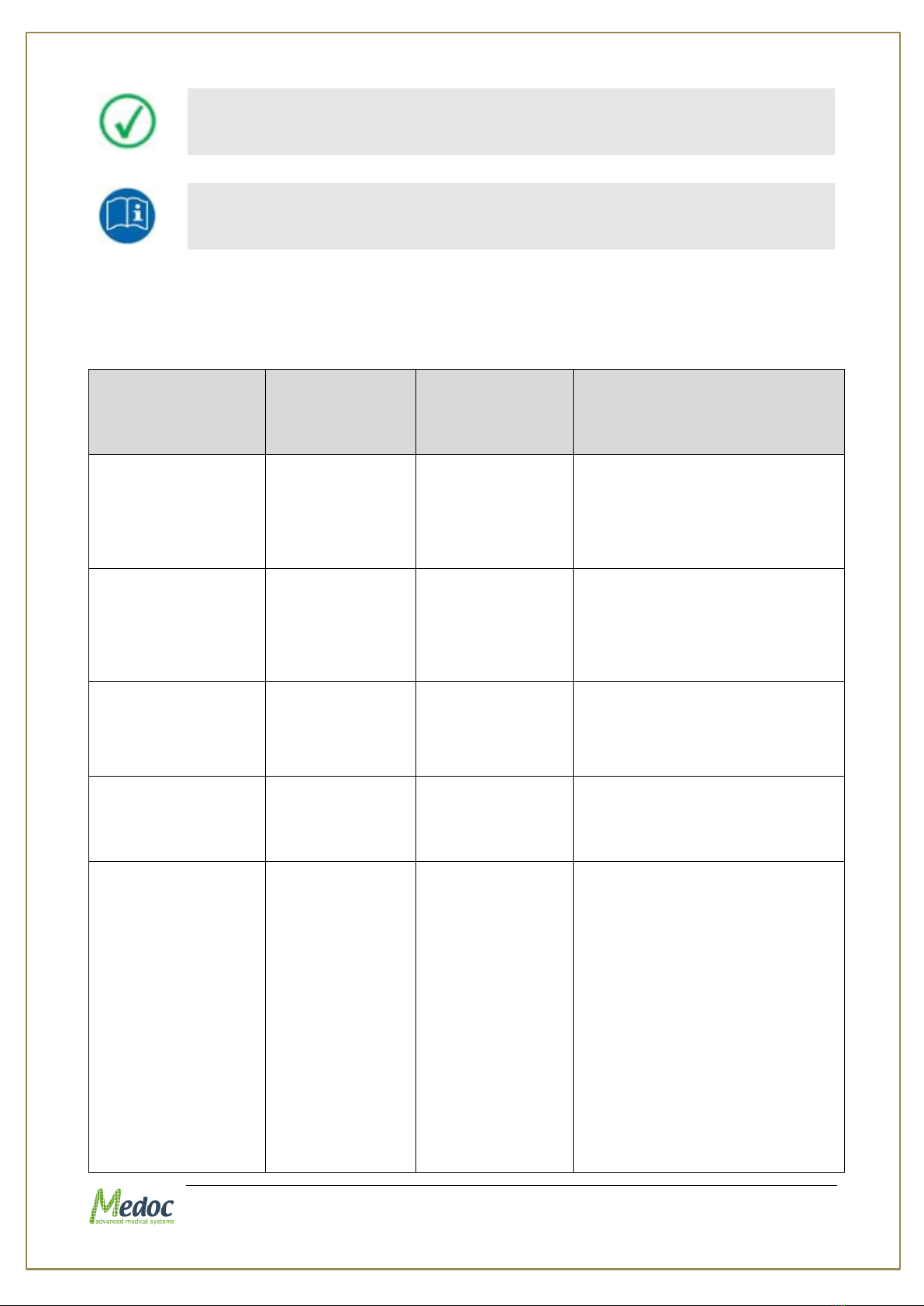
Advice: Refer to instruction manual/ booklet
INSTRUCTION: Indicates an instruction where it is important to follow
the user manual literally as described.
1.2 Intended use
The Q-Sense is a device for quantitative thermo-testing in the context of quantitative sensory
testing battery in compliance with Quantitative Sensory Testing (QST) protocols to detect and
quantify sensory loss and sensory gain aimed to precisely characterize somatosensory function
in patients.
1.3 Target Population and Contraindications
The Q-Sense can be used on both healthy subjects and patients suffering from wide range of
neuropathic, CNS and pain conditions. Minimum age reported in the literature is 6.
The only known contraindication is related to the skin on which the thermode is applied –it
must be used in contact with intact skin only. The thermode also intended to be applied on the
skin only, not on the eyes and the mouth.
1.4 Safety and Regulatory Summary
Read and follow all WARNINGS, CAUTIONS and NOTES provided in this manual. To avoid the
possibility of injury, damage to your system, or loss of data, always follow these precautions
during system operation.
The Q-SENSE system complies with safety requirements for medical electrical systems
(based on the IEC 60601-1 standard).
The Q-SENSE system complies with electromagnetic emission levels (based on table
201 in the IEC 60601-1-2 standard).
The Q-SENSE system complies with electromagnetic immunity levels (based on tables
202 and 204 in the IEC 60601-1-2 standard).
This device complies with 93/42/EEC MDD.
It is recommended to keep a distance of 3 meters between portable and mobile RF
communications equipment and the Q-SENSE (based on table 206 in the IEC 60601-1-
2 standard).
Q-Sense Technical Reference Manual
Proprietary 16 of 188
1.5 Safety Requirements
The Q-SENSE system can be tested according to IEC 62353 Recurrent test
and test after repair of medical electrical equipment.
Do not modify or replace any component of the Q-SENSE system.
Connecting or replacing external Q-SENSE accessories is allowed.
No modification of this equipment is allowed.
To avoid the risk of electric shock, this equipment must only be connected
to a supply mains with protective earth
Keep all liquids away from the Q-SENSE system.
Unplug the Q-SENSE system if it is not to be used for a long period of
time.
Do not block airflow anywhere around the Q-SENSE system.
1.5.1 Warnings
Only personnel properly trained to operate the Q-SENSE system should use this
system.
Do not turn on system power until all cables have been properly connected and
verified.
To avoid the risk of electric shock, this equipment must only be connected to a supply
mains with protective earth
Do not use any power supply which not supplied by Medoc (Medoc’s power supply
Cat.# DT 00017).
Do not use any electrode paste, gel, or other materials on the contact point between
the Thermode plate and the skin of the tested subject.
To reduce the risk of injury, place the Thermode on the subject only before starting the
test and while the test screen is visible. After the test is complete, remove the
Thermode from the subject’s skin while the test screen is still visible.
Connect the Thermode to the patient's skin ONLY during the test; not during system
Self-Test, programming or maintenance.
The computer that is used to operate the Q-SENSE system must be powered through a
Medical Grade Isolation Transformer only.
The use of accessories or cables other than those specified, with the exception of
accessories or cables sold by the manufacturer as replacement parts, may result in
increased emissions or decreased electrical immunity of the device.
Connecting any device or accessory that has no medical grade certificate to the Q-
SENSE system is not allowed.
Using a Thermode without the appropriate calibration table may result in potential
harm or injury.
Using the Q-SENSE system not according to instructions may result in potential harm
or injury.

Q-Sense Technical Reference Manual
Proprietary 17 of 188
Adverse Reaction: Skin irritation (in addition to pain sensation) beneath the probe has
been reported with the use of a stimulator, which was based on similar technology as
the Q-Sense device.
Be aware of potential risk of skin damage caused by wrong parameter
combination.
Use of this equipment adjacent to or stacked with other equipment should be
avoided because it could result in improper operation. If such use is necessary,
this equipment and the other equipment should be observed to verify that they
are operating normally.
of accessories, transducers and cables other than those specified or provided by
the manufacturer of this equipment could result in increased electromagnetic
emissions or decreased electromagnetic immunity of this equipment and result
in improper operation.
Portable RF communications equipment (including peripherals such as antenna
cables and external antennas) should be used no closer than 30 cm (12 inches)
to any part of the [ME EQUIPMENT or ME SYSTEM], including cables specified by the
manufacturer. Otherwise, degradation of the performance of this equipment
could result.
NOTE The EMISSIONS characteristics of this equipment make it suitable for use
in industrial areas and hospitals (CISPR 11 class A). If it is used in a residential
environment (for which CISPR 11 class B is normally required) this equipment
might not offer adequate protection to radio-frequency communication services.
The user might need to take mitigation measures, such as relocating or re-
orienting the equipment
1.5.2 Cautions
Proper use of this device depends on careful reading of all instructions and labels.
Turn OFF system power before connecting or disconnecting any system component(s)
or accessories. Otherwise, you may damage the device(s).
The Thermode is very delicate and can easily be damaged. Therefore, handle with
care.
If you disconnect any cables, take care to reconnect them correctly to prevent damage
to the system or components.
Inspect the power cord often for fraying or other damage. DO NOT operate the
apparatus if the power cord or plug is damaged.
The computer that is used to operate the Q-SENSE system must not be connected to a
network while it is used for running tests.
The Q-SENSE system does not require special precautions regarding EMC, and needs
to be installed and put into service according to this manual.
Portable and mobile RF communications equipment can affect medical electrical
equipment.
Use caution when using the Q-SENSE Thermode on patients with suspected
neuropathies as they may be more susceptible to soft tissue or nerve damage at
extreme temperatures. Also, patients with neuropathies may not be able to
properly discontinue use of the device during prolonged hot or cold stimulation.

Q-Sense Technical Reference Manual
Proprietary 18 of 188
1.5.3 Equipment Classification
Degree of protection against electric shock: Class I
Type of protection against electric shock: BF
Type of Operation: Continuous
Protection against ingress of liquids: Not protected against ingress of liquids
Ordinary equipment.
Computer must comply with IEC 950 - EN 60950 - UL 60950.
1.6 System Protection
1.6.1 System Self-Test
Upon start-up the system performs a self-test in which system sensors are being tested. If a
malfunction is detected, an appropriate message is displayed and the system cannot operate
until that malfunction is resolved.
1.6.2 Temperature Safety Mechanisms
Several safeguard mechanisms have been implemented in the system to safeguard against
extreme temperatures and to protect the tested subject and the unit.
Software protection mechanisms include:
Temperature upper and lower limits –In normal operation, Thermode temperature will
always be within these limits.
Time duration limits –Thermode temperature is limited in duration. If the Thermode
temperature maintains a specific temperature (or above) for a longer period of time
then specified for that temperature, the system will go into Safe Mode.
Safe Mode –a protective state of the system in which it is not possible to run tests. In
any case of suspected malfunction or if any modification is made to system hardware
settings, system will remain in safe mode until a system Self-Test is performed.
Hardware protection mechanisms include:
If the Thermode temperature reaches 57C an analog circuit overrides the system and
lowers the temperature gradually.
1.6.3 Thermode Detection
The system automatically detects that a Thermode is missing, and disables it in order to
protect both system and user.

Q-Sense Technical Reference Manual
Proprietary 19 of 188
1.7 Equipment Labels, Symbols, Warning Statements and
Abbreviations
Figure 1: Q-Sense Label
Table 1: Equipment Labels
Equipment Label
Description
Power switch ON/OFF
COM
Communications connector.
Date of Manufacture (YYYY-MM)
Manufacturer
Degree of protection against electric shock –Applied Part Type BF.
Warning - Connect the power cord to the power outlet, according to the
local electrical standards.
Refer to Manual
Disposal according to electronic scrap ordinance
I
O
Q-Sense Technical Reference Manual
Proprietary 20 of 188
Manual edition refers to current version of manufactured system
Medoc reserves the right to change specifications without prior notice,
in line with the company policy of constant product improvement
1.8 Electromagnetic immunity
The Q-Sense is intended for use in the electromagnetic environment specified below. The
customer or the user of the Q-Sense should assure that it is used in such an environment.
Immunity test
IEC 60601
test level
Compliance
level
Electromagnetic
environment –guidance
Electrostatic
discharge (ESD)
IEC 61000-4-2
±6 kV contact
±8 kV air
±6 kV contact
±8 kV air
Floors should be wood, concrete
or ceramic tile. If floors are
covered with synthetic material,
the relative humidity should be
at least 30 %.
Power frequency
(50/60 Hz)
magnetic field
IEC 61000-4-4
3 A/m
50 & 60 Hz
3 A/m
50 & 60 Hz
Power frequency magnetic fields
should be at levels
characteristic of a typical
location in a typical commercial
or hospital environment.
Electrical fast
transient/burst
IEC 61000-4-4
±2 kV for power
supply lines
±2 kV for power
supply lines
Mains power quality should be
that of a typical commercial or
hospital environment.
Surge
IEC 61000-4-5
±1 kV line(s)
and neutral
±1 kV line(s) and
neutral
Mains power quality should be
that of a typical commercial or
hospital environment.
Voltage dips, short
interruptions and
voltage variations
on power supply
input lines
IEC 61000-4-11
<5 % UT
(>95 % dip in
UT)
for 0,5 cycle
40 % UT
(60 % dip in UT)
for 5 cycles
70 % UT
(30 % dip in UT)
for 25 cycles
<5 % UT
<5 % UT
(>95 % dip in
UT)
for 0,5 cycle
40 % UT
(60 % dip in UT)
for 5 cycles
70 % UT
(30 % dip in UT)
for 25 cycles)
<5 % UT
Mains power quality should be
that of a typical commercial or
hospital environment. If a dip or
an interruption of mains power
occurs, the current of the Q-
sense may be dropped off from
normal level, it may be
necessary to use uninterruptible
power supply or a battery.
Table of contents
Other Medoc Test Equipment manuals

Popular Test Equipment manuals by other brands


DeFelsko
DeFelsko PosiTest AIR instruction manual

Henry Schein
Henry Schein Helix Test Kit Instructions for use

YOKOGAWA
YOKOGAWA 709830 user manual

Intellinet
Intellinet 515566 user manual

Wolfgang Warmbier
Wolfgang Warmbier PGT 120 user manual

Chauvin Arnoux
Chauvin Arnoux AEMC Instruments 6470-B user manual