PGT120 Art.Nr. 7100.PGT120
3 / 13 2014-11-27
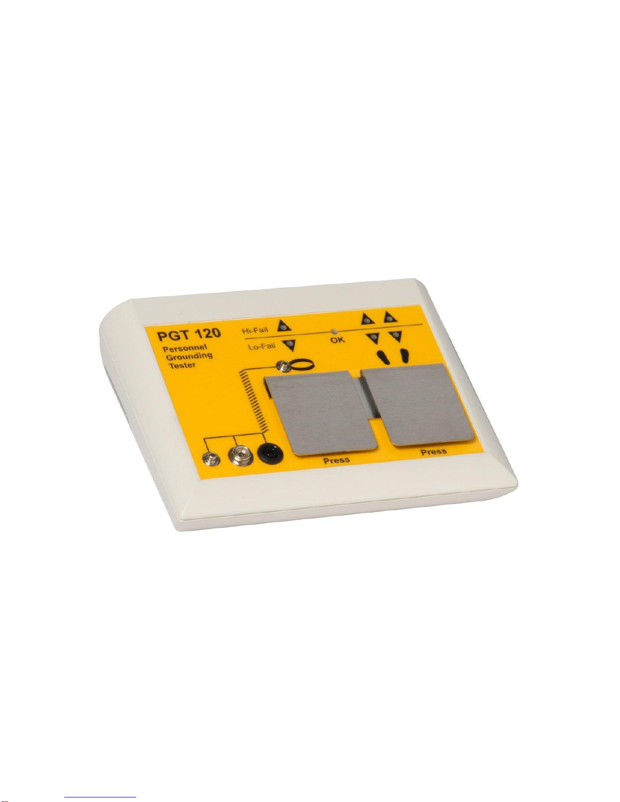
2 Introduction
The Personnel Grounding Tester PGT®120 is an electronic test instrument for
checking personnel grounding systems such as wrist straps, coil cords and footwear.
The PGT®120 is suitable for compliance verification of the above products, according
to the IEC 61340-5-1 Edition 1.0 (2007-08) or ANSI/ESD S 20.20 –2007 (2007-03).
The unit operates with 3 independent measuring circuits for the left shoe, the right
shoe and the wrist strap. This makes it possible to measure all the values at the
same time
It is possible to enable or disable separately the measuring circuits.
The order of tests is random.
Footwear measurement can be configured to measure in series with hands free
for passenger gates.
Visual and audible test results and a dry relay contact for door opener
Use the optionally available "Calibration Unit " Part No. 7100.PGT120.CU to
check the unit Hi and Lo limit values
2.1 Device return and environmentally compatible
disposal
The instrument is a category 9 product (monitoring and control instrument) in
accordance with ElektroG (German Electrical and Electronic Device Law). This
device is not subject to the RoHS directive.
We identify our electrical and electronic devices (as of August 2005) in
accordance with WEEE 2002/96/EG and ElektroG with the symbol shown to
the right per DIN EN 50419.
These devices may not be disposed of with the trash.
Please contact our service department regarding the return of old devices.
If you use batteries or rechargeable batteries in your instrument or accessories
which no longer function properly, they must be duly disposed of in compliance with
the national regulations.
Batteries or rechargeable batteries may contain harmful substances or heavy metal
such as lead (Pb), cadmium (Cd) or mercury (Hg).
The symbol shown to the right indicates that batteries or rechargeable
batteries may not be disposed of with the trash, but must be delivered to
collection points specially provided for this purpose.