Medora SolarBee SB10000DM User manual
SB10000DM OWNER’S MANUAL
Contents
Safety Instructions ...............................
Introduction ..........................................
Operation and Features .......................
Maintenance and Field Adjustment ......
General Electrical Schematic ...............
Troubleshooting ...................................
Specications .......................................
Model Drawing .....................................
Overall Machine Dimensions ................
Parts Identication ...............................
Warranty Statement .............................
Removal Instructions ...........................
Storage Instructions .............................
Installation Instructions ........................
1
4
5
16
29
32
35
36
37
38
39
42
48
50
506_20161129
Medora Corp. • 3225 Hwy 22 • Dickinson, ND 58601
Ph +1 701 225 4495 • +1 866 437 8076 • Fax +1 701 225 0002 • www.medoraco.com
© 2017 Medora Corp. • Dickinson, ND
1
Carefully read safety information when you see
any safety symbols:

2
Safety
Rotating Equipment
CAUTION: KEEP BODY APPENDAGES
OR LOOSE CLOTHING AWAY FROM
THE IMPELLER ASSEMBLY WHILE THE
MACHINE IS OPERATING! IF MAINTENANCE
IS REQUIRED, BE SURE TO TURN THE
SOLARBEE OFF FIRST! WEAR PROTECTIVE
GLOVES AND BE CAUTIOUS OF SHARP
LEADING EDGES ON IMPELLER BLADES
WHILE CLEANING! FAILURE TO FOLLOW
THESE WARNINGS COULD LEAD TO INJURY!
---------------------------------------------------------------------------------------------------------------------------------------
Crush Hazard
CAUTION: DO NOT REMOVE ANY FLOAT ARM OR TURNBUCKLE PINS
OR BOLTS WHILE THE SOLARBEE IS FLOATING IN THE WATER! THE
SOLARBEE MUST BE RESTING ON THE GROUND OR SAFELY SUPPORTED
TO RELIEVE THE FORCES ON THE FLOAT ARM AND TURNBUCKLE
STRUCTURES PRIOR TO DISASSEMBLY! FAILURE TO FOLLOW THIS
WARNING COULD LEAD TO SINKING THE SOLARBEE, OR CAUSE SERIOUS
INJURY!
Entanglement Hazard
WARNING: IF MOVING OR DEPLOYING
MOORING BLOCKS CONNECTED TO THE
ANCHOR CHAIN, BE SURE THAT YOU AND
OTHERS ARE CLEAR OF THE ANCHOR
CHAIN BEFORE SINKING THE MOORING
BLOCKS! LOWER THE MOORING BLOCKS
INTO THE WATER SLOWLY. FAILURE TO
DO SO COULD CAUSE SERIOUS INJURY OR
DEATH BY DROWNING!
---------------------------------------------------------------------------------------------------------------------------------------
THIN ICE HAZARD
WARNING: DURING WINTER CONDITIONS WHEN THE
SOLARBEE IS FROZEN IN OR PARTIALLY FROZEN IN,
THE MACHINE SHOULD NOT BE APPROACHED. THE
ICE AND SNOW AROUND THE SOLARBEE SHOULD NOT
BE ASSUMED TO SUPPORT WEIGHT. FAILURE TO DO
SO CAN RESULT IN SERIOUS INJURY OR DEATH BY
DROWNING OR HYPOTHERMIA!!!
3
Safety
Signage and Instuctions - The SolarBee is supplied with warning signage and instructions written
in the english language. It is very important that all operators and the public having access to the
SolarBee equipment be informed of the associated safety hazards. If English is not the dominant
language in the region, Medora Corporation strongly recommends that all warning signage and
instructions be translated to the dominant language.
For SolarBee machines installed into a public reservoir where there is open access to the machine, it
is strongly encouraged to properly notify the public of its presence. To avoid an injury or damage to
the equipment, the public should remain at least 5 meters away from the machine at all times.
Below is a sample public notication sign:
PUBLIC INFORMATION NOTICE
The _______ has installed SolarBee solar-powered high-flow long-distance circulation
equipment to improve the water quality and to enhance the recreational value of the lake.
Some facts about SolarBee SB10000DM / 10000 gpm Circulators:
• SolarBees come in various sizes, the largest unit
circulates 14 million gallons per day. The machine in
this lake circulates 14.0 million gallons per day.
• The machine runs during daylight & night hours entirely
powered by solar energy.
• SolarBee long distance water circulation helps:
o prevent lake water stagnation,
o control blue-green algae blooms,
o improve the lake ecosystem,
o provide a healthy environment for fish, frogs,
crayfish, and other aquatic organisms.
• SolarBee units have an expected life of 25+ years.
• More information on this technology is available at
www.medoraco.com
.
Help Us Keep the SolarBee Working.
Report vandalism, by calling:
______________
For your safety, and to help achieve the water quality goals for this lake, please do not go near the machines.
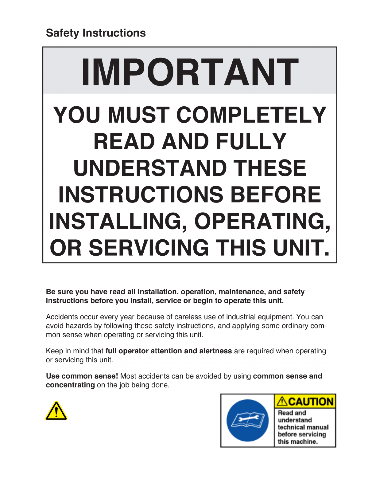
Lock Out - When the On/Off
switch is in the On position,
the SolarBee may start up at
any time. The SolarBee On/
Off switch can be locked out
by placing a pad lock through
the shroud of the switch while it
is in the Off position. The On/
Off switch is to be used as the
emergency stop.
EU Declaration of Conformity
Trade Name: SolarBee
Responsible Party: Medora Corporation
Address: 3225 Hwy 22
Dickinson, ND 58601 USA
Telephone: 1-866-437-8076
This equipment complies with:
• Machinery Directive 98/37/EC
• Noise Emissions of Outdoor
Equipment Directive 2004/14/EC
• Electromagnetic Compatibility Directive
(EMC) 89/336/EEC

4
Thank you for purchasing this SolarBee.
We trust that you’ll nd the SolarBee to be
very effective in treating your water. Every
SolarBee is tested and inspected at our
manufacturing facility before being delivered
to you. An experienced and trained Medora
Corp. eld team will deliver and install
your SolarBee. During the installation, the
eld team will present to you a summary
of the background, operation, and routine
maintenance of your SolarBee. They are
very helpful and willing to answer any eld
questions you may have.
The SolarBee has proven to be effective in a
variety of applications including wastewater,
stormwater, freshwater, potable water, salt
water, and many more. Research and
development continue to be a high priority
in order to provide you with the up-to-date
knowledge and best technology available for
your application. Extensive design efforts
have been made to make the SolarBee easy to
maintain with high quality, long life parts.
If at any time you feel that your SolarBee is not
operating at its full potential, feel free to contact
the main ofce where a knowledgeable Medora
Corp. service team is available to offer help.
There are methods of eld adjustment that may
be benecial following the installation. Our
service team will gather the latest information
on your application and combine it with their
experience to optimize the performance of your
SolarBee.
Technology Features
• Solar power achieving day/night operation
• Durable brushless motor
• Advanced controls system
- Scheduled-reverse, and anti-jam routine
- SCADA outputs, machine monitoring
- SD Card reprogrammable
- Seasonal RPM
• Robust frame and oat arm structures
• Swinging PV module gates
• PV modules with angle adjustment
• Quick detachable impeller
• Lower oating prole, improved aesthetics
• Smooth, quiet operation
Medora Corporation Factory And Delivery Fleet

5
The SolarBee is designed to circulate water
by bringing water from below and sending it
out across the top in a thin layer causing a
mixing effect. The laminar layer ows outward
radially, in diverging “stream lines” from the
distribution dish. As it does, vertical ow is
induced in between the water being drawn
below and the water above. At the level of the
ow intake, water is drawn from all corners of
the pond. As this lower layer of uid makes
its way inward with converging streamlines
to the SolarBee, the water is forced upward,
toward the surface, providing gentle mixing,
de-stratication, and surface renewal.
The SolarBee obtains all the energy it needs
from the sun. Its solar panels provide power
to the onboard battery which energizes the
drive system’s controls and motor. The new
Technology allows excess solar energy to be
stored during the day and used during the
night allowing the SolarBee to operate during
the night without being connected to the grid.
During operation, a visible ow can be
observed coming off the distributor dish
and spreading outward. The impeller of the
SolarBee is designed to operate at full speed
when there is sufcient sunlight and battery
charge. The rpms may drop down some
during the later night and early morning when
the battery uses up its charge after a longer
period of overcast days. In severe sunlight
limited conditions, the machine may slow
down or stop temporarily to protect the battery
from damage.
SB10000DM Flow Pattern
Operation
Flow Coming Off Distributor Dish
6
Features
The SolarBee with technology includes new
features which enhance its performance
through more efcient and durable
components, improved operation monitoring
capablilities, easy component access, and a
robust frame structure.
Solar / Electronics
Photovoltaic (PV) Modules -The PV modules
are often referred to as the solar panels. The
SolarBee uses 100% solar energy to provide
day/night operation. The PV modules collect
solar power to operate the machine with
excess left over to charge an onboard 12-volt,
deep cycle battery. The SolarBee has 3 80-
watt PV modules which individually connect to
the digital controller. A bird deterrent is located
directly above the PV modules to prevent bird
fouling.
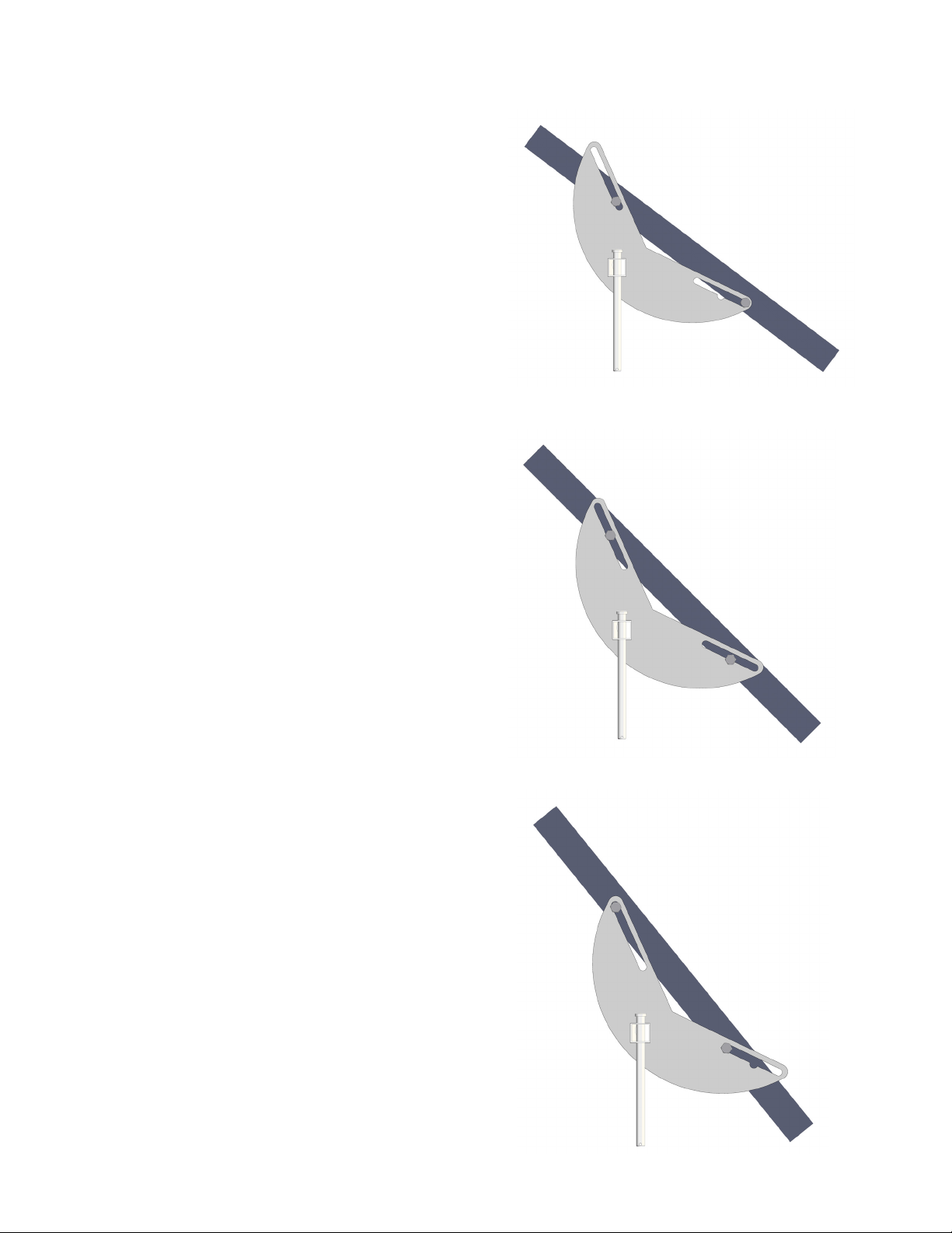
The PV modules have 3 angle settings
that are set at the factory based on solar
energy availability unique to the customer's
geographic location. The attest position is a
35 degree angle for customers located where
solar power availability is greatest. The mid-
range setting position is a 45 degree angle for
customers where solar power availability is
moderately available. The steepest position
is a 55 degree angle intended for winter
conditions to prevent snow and ice buildup
from lasting a long time period on the PV
modules (following winter conditions, the PV
modules should be returned to their original
position to maximize solar energy collection).
55 Degree
45 Degree
35 Degree

7
For cable tethered anchoring, the north facing
panel may be ipped to face the south using
a special panel gate. A tethered machine is
xed and will not rotate, so the north facing
panel will receive the least sunlight, unless
ipped using the special gate. For mooring
block anchoring, this is not an option due
to the machine rotating about the mooring
blocks.
Each PV module is xed to a gate that opens
up allowing quick access to the interior
components of the machine. Each gate opens
by simply removing a pin on the latch end.
Onboard Battery - The onboard battery is
located directly below the dish in a stainless
steel compartment. During operation,
the battery is submerged in the water to
maintain a stable-temperature environment
that increases its performance and life. The
battery is double-walled to isolate its contents
from the water it is submerged in.
The onboard battery stores excess power from
the solar panels during the day and operates
the machine using the stored power during the
night and extremely overcast days.
PV Module Gate
Hinge End
Latch End
Features
Battery
Compartment
Onboard Battery

8
Features
Digital Controller
PV Module
Gate Open
Front Face Of Digital Controller
Left Side Face Of Digital Controller
Digital Controller - The digital controller is
located near the top center of the SolarBee.
The digital controller can be easily accessed
by opening the PV module gate directly
above and in front of it. The digital controller
is constructed with a NEMA 4X (IP 66)
Enclosure.
All solar energy collection and motor operation
are managed by the digital controller. This
component has two primary functions: (1) To
direct and divide the power being collected by
the PV modules between the brushless motor
and battery. (2) To serve as the main control
center that operates the brushless motor.
There are 3 PV module connections located
on the front face of the digital controller. If
the onshore power accessory was purchase,
a connection will be located on the right side
face. The onshore connection is used only
in applications where onshore grid power is
desired.
The left side face of the digital controller
contains the brushless motor connection,
battery connection, and On/Off switch. The
On/Off switch activates power to the motor.
When the switch is turned to the Off position,
the motor will not operate. The charging
function of the controller will continue to
charge the battery even when the switch is
turned off.

9
Features
SCADA outputs offering machine operation
parameters reside within the digital controller.
Please contact Medora Corp. if you are
interested in receiving these parameters.
Motor Controller - The motor controller is
located near the motor just below the top plate
of the SolarBee. The motor controller is sealed
in line with the electrical cord that runs to the
brushless motor.
The motor controller on the SolarBee receives
power and signals from the main control center
located inside the external enlosure. These
signals are used to operate the brushless
motor at the commanded speed. The motor
controller also sends feedback signals back up
to the main control center.
Due to the high frequency of communication
between the motor controller and brushless
motor, the two components need to be located
close to one another. This is the primary
reason for having the motor controller located
directly on the SolarBee.
All electronic connections on the SolarBee
equipment should only be used for the inputs
or outputs that they are labeled and designed
for. If any of the leads going into the electronic
controller are disconnected, be sure when re-
connecting to place them in the proper position.
Wiring - All electric wiring includes corrosion-
resistant, industrial cords with molded, weather
and watertight connectors. The connectors are
indexed to prevent improper wiring. A general
electrical schematic can be found in the
Maintenance and Field Adjustment section.
SCADA Signal From SolarBee Unit
Durable Wiring And Connectors
10
Features
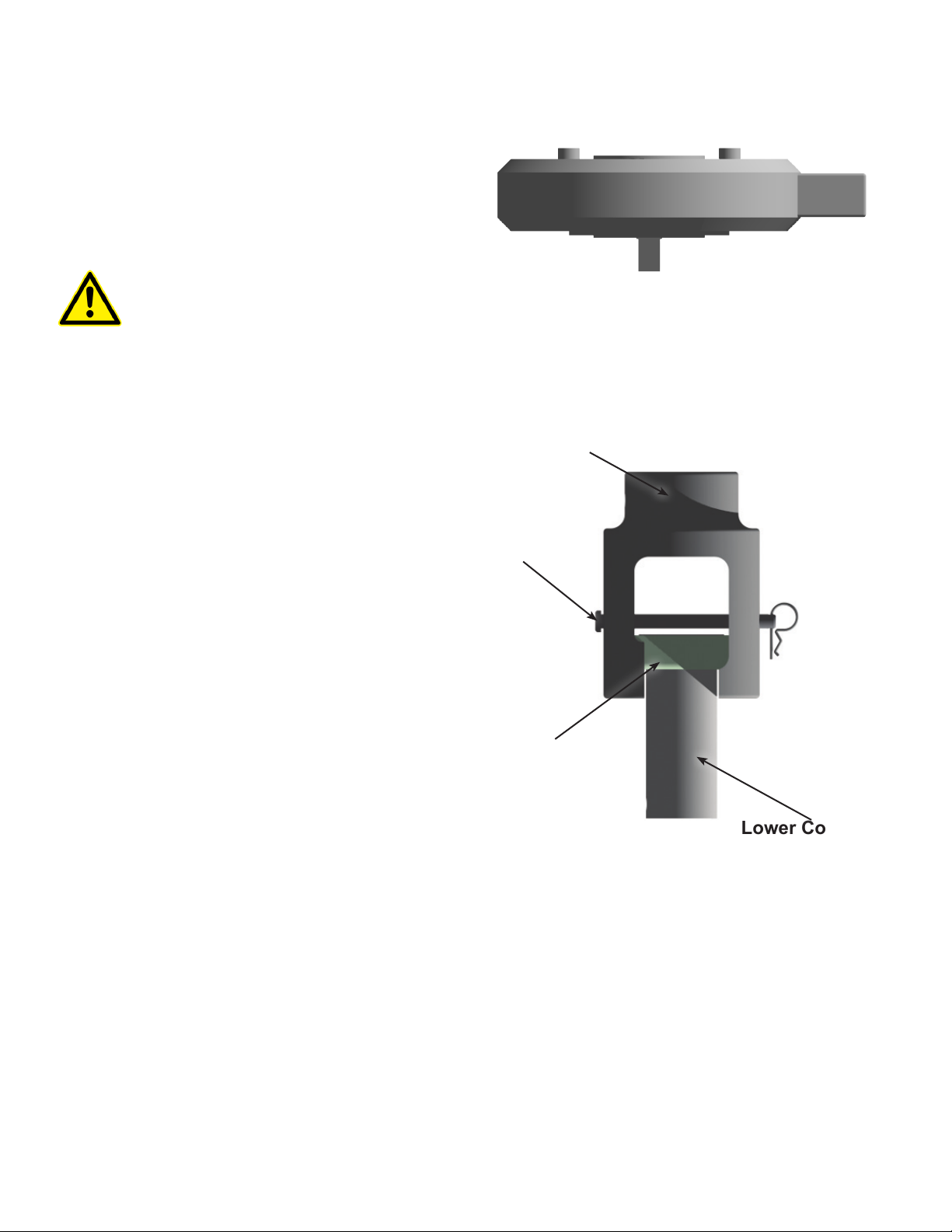
Upper Coupling
Lower Coupling
Coupling Sleeve
Clevis Pin
Brushless Motor / Impeller
Brushless Motor - The brushless motor is
located directly below the Top Deck. 4 bolts
run down through the Top Deck and into the
housing of the brushless motor fastening it
onto the machine.
CAUTION: THE BRUSHLESS MOTOR
WEIGHS APPROXIMATELY 80 LBS (36KG).
DO NOT REMOVE WITHOUT DISCUSSING
THE PROCEDURES AND EQUIPMENT
NECESSARY WITH A SOLARBEE SERVICE
TEAM MEMBER.
The brushless motor is built to be very
durable. The housing is constructed of casted
aluminum. The brushless motor runs very
quietly and smoothly. It does not require any
maintenance. A drive shaft extends through
the bottom center of the housing.
Shaft Coupling - The shaft coupling connects
the brushless motor drive shaft to the impeller
shaft. The shaft coupling is located directly
below the brushless motor and is made up
of 3 main components. These components
are called the upper coupling, lower coupling,
and coupling sleeve. The shaft coupling is
designed to allow quick disconnect for removal
of the impeller assembly. Disconnecting the
impeller shaft from the brushless motor shaft
is simply accomplished by pulling out a pin
and requires no tools. The upper coupling
remains attached to the brushless motor while
the lower coupling and coupling sleeve remain
on the impeller shaft.
Brushless Motor
11
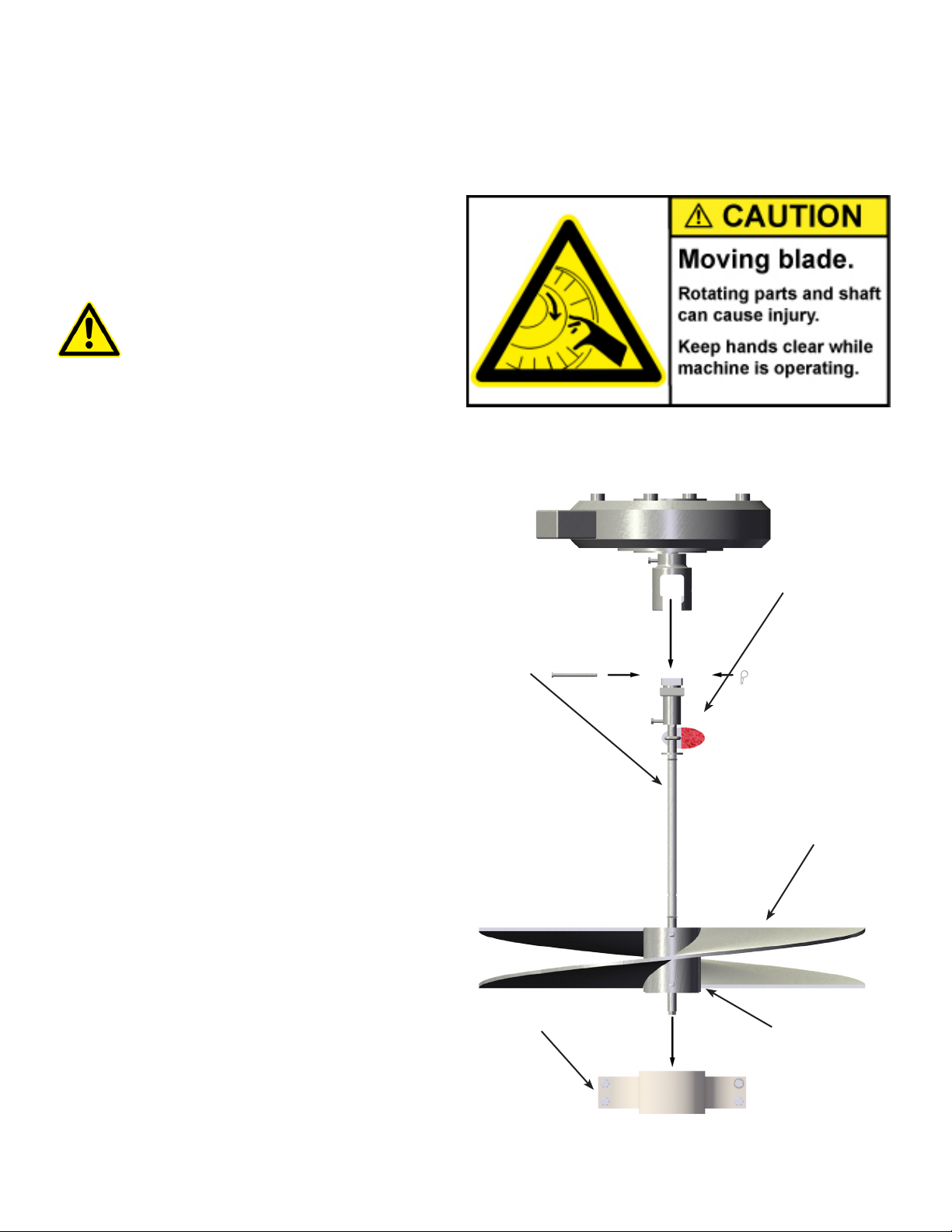
Features
Impeller Assembly - The impeller assembly is
made up of the stainless steel impeller shaft,
stainless steel ag indicator, freeze sleeve,
stainless steel impeller blades, and plastic
impeller bushing. The impeller assembly is
easily removed by pulling a pin on the shaft
coupling.
CAUTION: KEEP BODY APPENDAGES
OR LOOSE CLOTHING AWAY FROM
THE IMPELLER ASSEMBLY WHILE
THE MACHINE IS OPERATING! IF
MAINTENANCE IS REQUIRED, BE SURE
TO TURN THE SOLARBEE OFF FIRST!
The ag indicator is xed to the shaft and used
as a visual indicator of the impeller shaft's
rotational speed.
A food grade oil-lled, Teon freeze sleeve
secured with o-rings surronds the impeller
shaft. The freeze sleeve is free to rotate on
the shaft. If the water should freeze around
the machine, the freeze sleeve will stand still,
frozen in by the ice, but inside the plastic
sleeve, the impeller shaft will be turning.
The impeller blades are welded to a hub that
is securely fastened to the impeller shaft. The
impeller is designed to gently pump water from
below and can handle up to 4-inch (10cm)
spherical solids.
The impeller bushing is a smooth collar that
the impeller shaft tip ts into. The impeller
bushing aligns and centers the impeller shaft
within the machine.
Turn SolarBee Off Before Performing Maintenance
Flag Indicator
Freeze Sleeve
Impeller Bushing Block
Impeller Blades
Impeller Hub
12
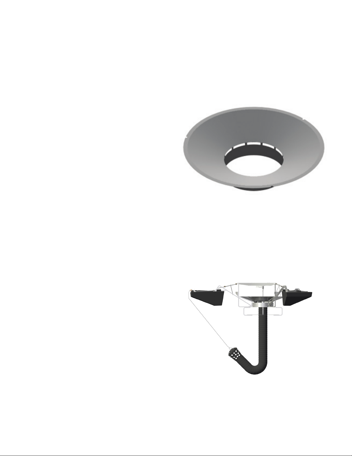
Features
Distributor Dish / Hose / Intake Plate
The distributor dish, structural members,
structural fasteners, and mounting brackets are
constructed of stainless steel.
Distributor Dish - Near-laminar ow is
achieved by the SolarBee due to its uniquely
designed distributor dish. The impeller
rotates while sitting within the lower half of the
distributor dish. There are also small water
passages located below the dish to strengthen
the induced ow effect (water movement
occuring between the lower water layer
entering the machine and the upper water layer
leaving the dish).
The top lip of the distributor dish is set
approximately 2- inch to 2.5-inch (5.1cm to
6.4cm) below the surface of the water to
achieve best ow results. The distributor dish
depth is set by rotating the turnbuckles located
on the oat arms.
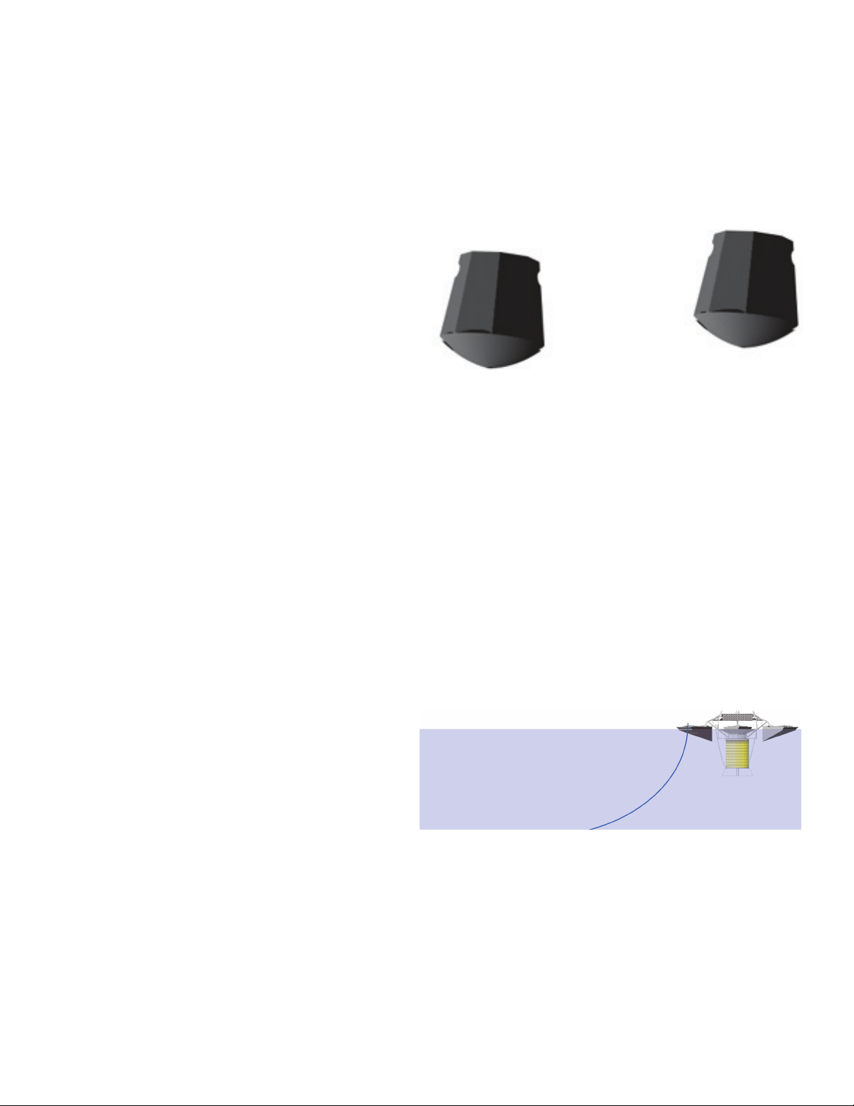
Hose / Intake Plate - On the SB10000DM ,
the intake plate is directly below the distributor
dish and the hose extends down through the
intake plate. The Dual Mix design allows the
SolarBee to draw water from different depths.
Most of the water drawn into the SolarBee
enters above the intake plate. A small amount
of water is also drawn into the hose through the
strainer. The majority ow through the intake
plate circulates the top water column while the
smaller amount of ow through the hose slowly
processes the lower water column.
SB10000DM Intake And Hose Conguration
Distributor Dish
Strainer
Hose
Intake Plate

13
Float Arms / Floats
The SolarBee contains 3 oat arms and 3
oats. The oat arms allow vertical positioning
of the machine and the oats provide
buoyancy.
Float Arms - The oat arms are constructed
of stainless steel components. They connect
the oats to the central machine structure.
Each oat arm has a sturdy turnbuckle.
The turnbuckles can easily be rotated to
adjust the vertical height of the distributor
dish. Lengthening the turnbuckle (rotating
clockwise) will raise the lip of the distributor
dish, whereas shortening the turnbuckle
(rotating counter-clockwise) will cause the lip
of the distributor dish to lower.
The turnbuckle and oat arm structure
components are constructed with robust
stainless steel materials allowing the SolarBee
to operate in severe environments without
being damaged. The turnbuckle is self
locking. Simply rotate the handle to expand
or collapse the turnbuckle for dish depth
adjustment.
It is important to check the distributor dish
depth routinely. The SolarBee naturally
drops into the water over time due to biomass
buildup and trapped air escaping from the
hose. If the distributor dish lip is too high, the
water coming off the lip may become turbulent
and the ow rate of the machine may be
reduced.
Features
Turnbuckle
Float Arm
2-in to 2.5- in (5.1-cm to 6.4-cm)
Distance Between Distributor Dish And Water Level
Handle
14
If the distributor dish lip is too low, the water
coming off the lip will ow just underneath the
surface of the pond and the surface will not be
renewed.
Each oat arm is connected to the central
machine structure with 1 bolt and 1 pin. Each
oat is connected to the oat arm by 2 pins.
The turnbuckle can be removed from the oat
arm by pulling a pin, but should only be done
when the unit is resting on the shore.
If re-attaching the turnbuckle to the oat
arm, be sure that each threaded end of the
turnbuckle together are screwed all the way
in or all the way out before re-attaching. If
threaded ends are not equally expanded or
collapsed before xing the ends, the turnbuckle
will have limited adjustment.
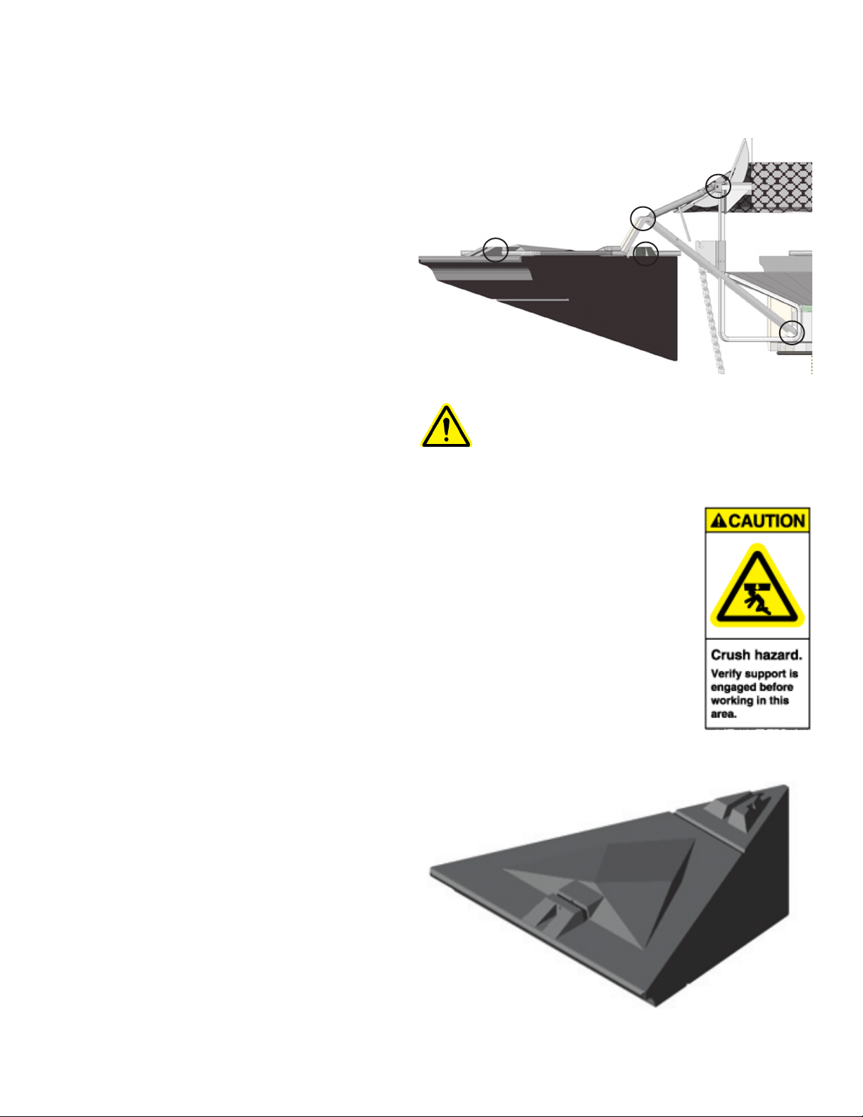
Floats - The SolarBee has 3 oats, made from
high density Polyethylene. The oats are lled
with a Polystyrene closed-cell foam for long
term buoyancy. The oats have a uniquely
designed shape to:
• Minimize the interference with the water
ow on the surface coming off the
distributor dish.
• Have a low prole above the water for
minimizing wind resistance and
offering less exposure to vandalism.
• Avoid being crushed by ice pressure.
• Provide extra buoyancy when needed
without going much deeper into the
water.
Features
Float Arm Connection Points
Pin
Pin
Pin
Bolt
Pin
Float
CAUTION: DO NOT REMOVE ANY
FLOAT ARM OR TURNBUCKLE
PINS OR BOLTS WHILE THE
SOLARBEE IS FLOATING IN THE
WATER! THE SOLARBEE MUST
BE RESTING ON THE GROUND OR
SAFELY SUPPORTED TO RELIEVE
THE FORCES ON THE FLOAT ARM
AND TURNBUCKLE STRUCTURES
PRIOR TO DISASSEMBLY!
FAILURE TO FOLLOW THIS
WARNING COULD LEAD TO
SINKING THE SOLARBEE, OR
CAUSE SERIOUS INJURY!
15
Features
Mooring Blocks
Mooring Block System (7:1 Scope)
Anchoring Systems
The SolarBee uses one of the following
anchoring systems. The mooring block
system consists of submerged anchors
and doesn't require lines running from the
shoreline. The tethering system uses cable
that spans across the pond or reservoir
connecting to tethering posts on the shorline.
Mooring Block System - The mooring block
system consists of two mooring blocks made
of high density Polyethylene with smooth,
rounded bottoms. The smooth bottoms
prevent any damage being done to a pond
liner or reservoir bottom. The mooring blocks
are concrete lled and weigh approximately
70-lbs. (31.75 kg).
Stainless steel anchor chain is used to
connect the mooring blocks to the SolarBee at
the oat plate on one of the oats. The anchor
chain contains swivels approximately every
15-ft (4.5m) to prevent the chain from twisting
and tangling.
A 7:1 scope is generally preferred for the
length of anchor chain. For example, if the
pond is approximatley 10-ft (3m) deep, the
anchor chain will go from the rst mooring
block out 70-ft (21m) to the machine. The 7:1
scope prevents the machine from moving
during high wind and wave conditions. The
two mooring blocks are generally spaced
apart along the anchor chain by a distance
approximately the depth of the water. From
time to time, as determined by specic
circumstances, the scope can be reduced to
5:1.
Movement of machine - For a SolarBee anchored
by a mooring block system, the machine may
rotate 360 degrees around the mooring blocks on a
radius of approximately 5X to 7X the water depth.
For example, a machine that is in 10 ft (3m) of
water may travel on a 70 ft (21 m) radius from the
location of the mooring blocks

16
Features
Tethering System
Following severe weather conditions (greater
than 80-mph (129 km/hr) wind, higher than 4-ft
(1.2m) waves, or ice thaw), it is possible for
the SolarBee to drag the anchors and move
out of position. If this should happen, the pond
or reservoir operator will need to re-locate the
machine to its original position.
WARNING: IF MOVING OR DEPLOYING
MOORING BLOCKS CONNECTED TO THE
ANCHOR CHAIN, BE SURE THAT YOU AND
OTHERS ARE CLEAR OF THE ANCHOR
CHAIN BEFORE SINKING THE MOORING
BLOCKS! LOWER THE MOORING BLOCKS
INTO THE WATER SLOWLY. FAILURE TO
DO SO COULD CAUSE SERIOUS INJURY
OR DEATH BY DROWNING!
Tethering System - The tethering system
constists of 2 tether posts or duckbill anchors
set into the shoreline across from one another.
A stainless steel cable is strung across the
pond or reservoir and tied to both tether posts.
The SolarBee has 2 short chains running from
two of the oat plates on the machine out to the
cable line running across the pond or reservoir.
The tethering system is used in applications
where the body of water is very narrow or
the Mooring Block System is not applicable.
Following severe weather conditions (greater
than 80-mph (129 km/hr) wind, higher than 4-ft
(1.2m) waves, or ice thaw), it is possible for
the tether posts to pull partly or completely out
of the ground. If this should happen, the pond
or reservoir operator will need to re-locate the
machine to its original position.
Movement of machine - For a SolarBee anchored
by a tether system, the machine will have limited
movement, however slack will be left to allow for
water uctuation. The tether line slack will be
eld determined based on tether line span and
expected water uctuation. The SolarBee will not
rotate when it is anchored using the tether system.

17
Maintenance and Field Adjustment
SolarBee Orientation During Install
The performance of the SolarBee has
proven to increase tremendously when its
operator understands the operation of the
machine and knows how to carry out eld
adjustment procedures. During installation,
an experienced Medora Corp. eld team
thoroughly trains the operator on how to keep
the SolarBee performing at its best.
In most applications, it is strongly encouraged
that the operator have a boat to perform
routine checkups and eld adjustment
procedures on the SolarBee. A large,
expensive boat isn't necessary. Our Medora
Corp. eld teams use 12 ft (3.65m) Jon boats
that work ne for almost all applications.
It is extremely important that safety comes
rst every time the SolarBee is inspected or
having maintenance procedures performed. It
is strongly encouraged that anyone working on
or near the machine follow these rules:
Wear a personal oatation device
Stay focused and alert
Turn the SolarBee off before working on it
Stay clear of parts while they are moving
To turn the SolarBee motor off, turn the On /
Off switch to the off position. To completely
power down the digital controller, remove all
power sources in the proper sequence.
DIGITAL
CONTROLLER
ON / OFF
SWITCH
18
Maintenance and Field Adjustment
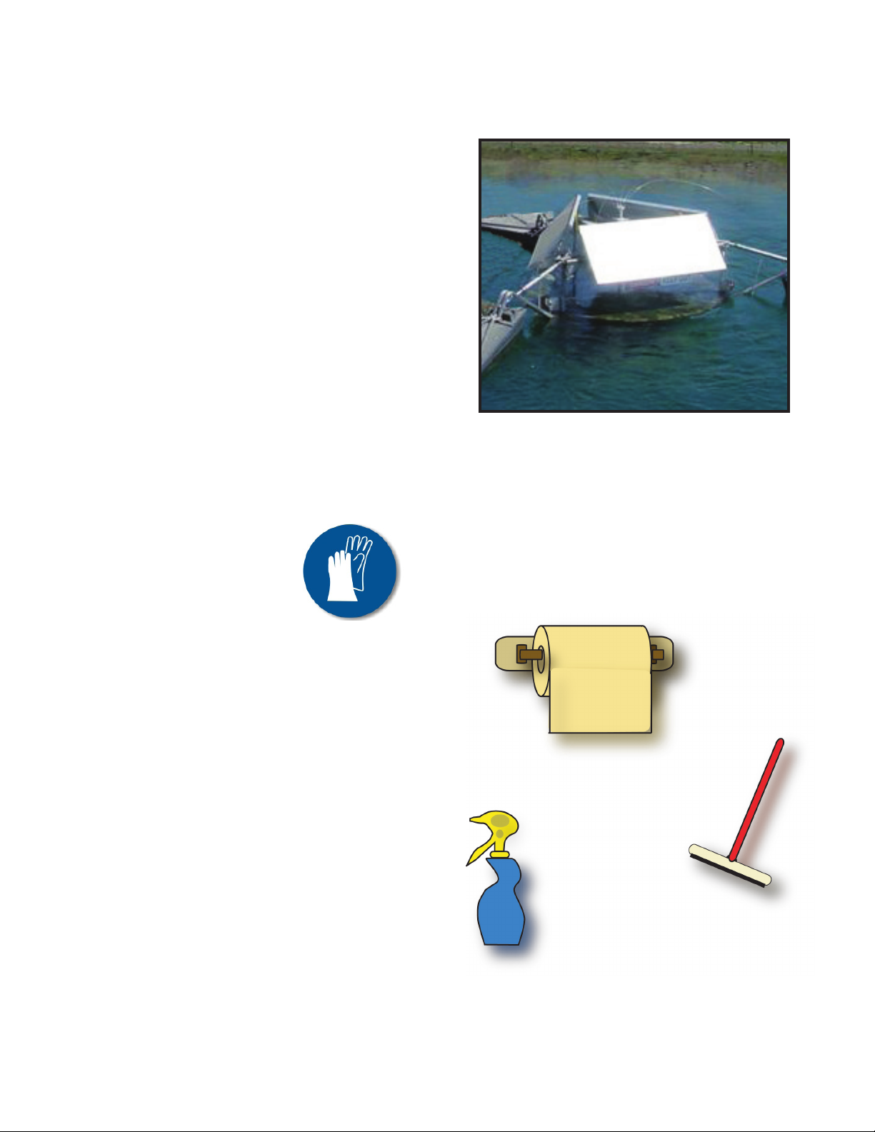
PV Module Cleaning
The solar panels are the SolarBee's primary
source of energy, so it is important that they
be kept clean. Over time, dust collects on the
PV modules or birds are not kept completely
off by the bird deterrent resulting in the panel's
effective surface area decreasing.
PV Module Cleaning
TOOLS RECOMMENDED:
Squeegee
Glass Cleaner
Paper Towel or Wash Cloth
STEP 1: Rinse panel face off with water.
STEP 2: Use squeegee, towel, or wash cloth to
clean surface of panel.
STEP 3: Remove any streaks or lms using
glass cleaner and paper towel/wash cloth.
STEP 4: Repeat Steps 1 through 3 for each
solar panel.

19
Maintenance and Field Adjustment
Solar Panel Angle Adjustment
The SolarBee technology includes tilting PV
modules to allow for optimal solar collection for
different geographical regions and changing
sun position during the seasons.
Use 35 Degree (Flattest Position):
Where - Locations south of 40 degree latitude.
When - During fall, summer, and spring or year
round if no adjustment is preferred.
OR
Where - Locations north of 40 degree latitude.
When - During summer only.
Use 45 Degree (Middle Position):
Where - Locations north of 40 degree latitude
(Especially Great Lakes Region and Canada).
When - During spring and fall or year round if
no adjustment is preferred.
OR
Where - Locations south of 40 degree latitude.
When - During winter
Use 55 Degree (Steepest Position):
Where - Locations north of 40 degree latitude.
When - During winter season or periods of
abundant snow (The steep angle will help
prevent snow from building up on the panels).
TOOLS RECOMMENDED:
Two 1/2" or 13mm wrenches
STEP 1: Loosen 2 bolts on each end of the PV
module using 1/2" or 13mm wrenches as shown in
the gure below.
Bolts
STEP 2: Firmly grip the PV module and slide it up
or down the tracks until it is in the desired position.
For each of the three recommended angle settings
listed, there is a slot in the top tracks at both ends
that the top bolt will drop into.
STEP 3: Once the PV module is in the desired
position, tighten all four bolts.
STEP 4: Repeat steps 1 through 3 for other two
solar panels
Bolts
Other Medora Water System manuals

Popular Water System manuals by other brands


Everpure
Everpure Opaque Housing A-20 20 Specification sheet

salmson
salmson Siriux Series Installation and starting instructions

Nikken
Nikken Aqua Pour operating manual

Everpure
Everpure Replacement Cartridge 7TO Specification sheet

oventrop
oventrop Regumaq X-25 operating instructions

Wayne
Wayne Jet Pump Water Systems Shallow Well Operating instructions and parts manual

Elkay
Elkay MFWSF100 Mounting instructions

Naked
Naked NKD-R Installation & start?up guide

HYDRO GUARD
HYDRO GUARD LongNeck Standard HG-31 User's operation manual

Addie Water Systems
Addie Water Systems OXIDIZER PLUS owner's manual

J.E. Adams
J.E. Adams 9730 manual

ABANTERA
ABANTERA Neo GreenWashing user manual