EcoQuest SpringHouse User manual
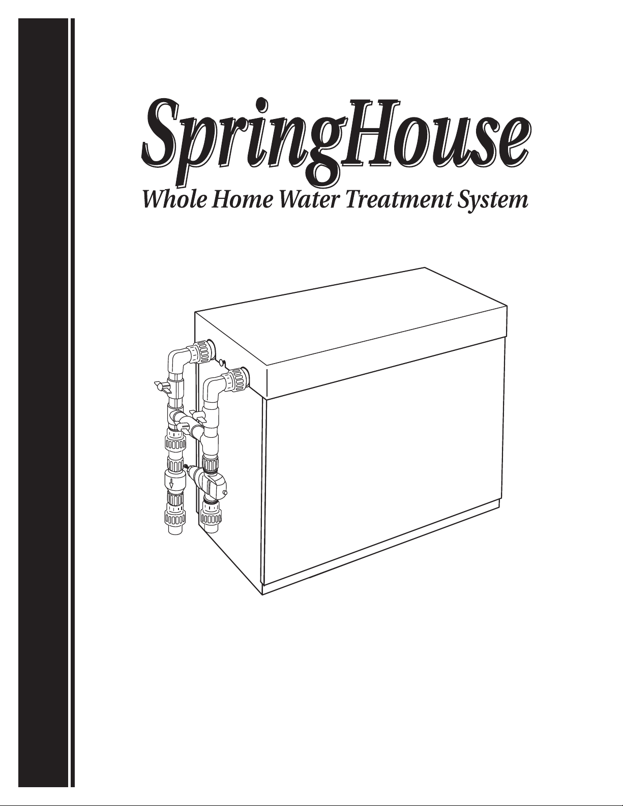
Owner’s Manual
2
PLEASE READ BEFORE INSTALLATION!
Congratulations on your decision to deliver the finest quality water available to every tap in your home or business. The following is
important information that will help you get the most out of your SpringHouse system and ensure the Warranty and operation of your
SpringHouse for years to come.
SpringHouse’s unique combination of filtration and UV treatment improves taste and reduces odor throughout your plumbing system.
In addition this premier system reduces or eliminates sediments, various minerals, chemicals, microorganisms, and bacteria, as well as
decreases scale buildup in pipes and fixtures.
The UV system has both audible and visual alarm system is to ensure your UV system is functioning properly at all times.
SpringHouse can be installed indoors or outdoors, but must be protected from freezing, excessive heat, and direct sunlight. Failure to
do so will void the warranty. The unit is also equipped with a drip pan and drain system for attic installation. The influent and effluent will
accept 1 inch pipe and is plumbed throughout with 1 inch “schedule 80” PVC.
Be sure that there is at least 74" of room, floor to ceiling, in the location where your SpringHouse is to be installed. Otherwise you will
not be able to install and/or remove the UV lamp and the quartz sleeve.
NOTE: Installation must be done by a qualified plumber in accordance with local codes. Failure to do so can result in damage not
covered by your SpringHouse warranty.
SpringHouse’s unique design allows for easy maintenance and operation. The System Bypass function allows your water source to be
bypassed for servicing, or in situations that call for the use of large quantities of water where this level of treatment is not required, such as
pool filling and lawn watering, though using SpringHouse water for these functions is certainly an option if you choose.
NOTE: This product is not intended to purify non-drinkable sources of water. Do not use where the water is micro-biologically unsafe, or
if water is of unknown quality. SpringHouse is not designed to significantly reduce Total Dissolved Solids (TDS) or hardness. SpringHouse
is not designed to remove greater than 2ppm Iron, 1ppm Manganese, or 0.5ppm Hydrogen Sulfide.
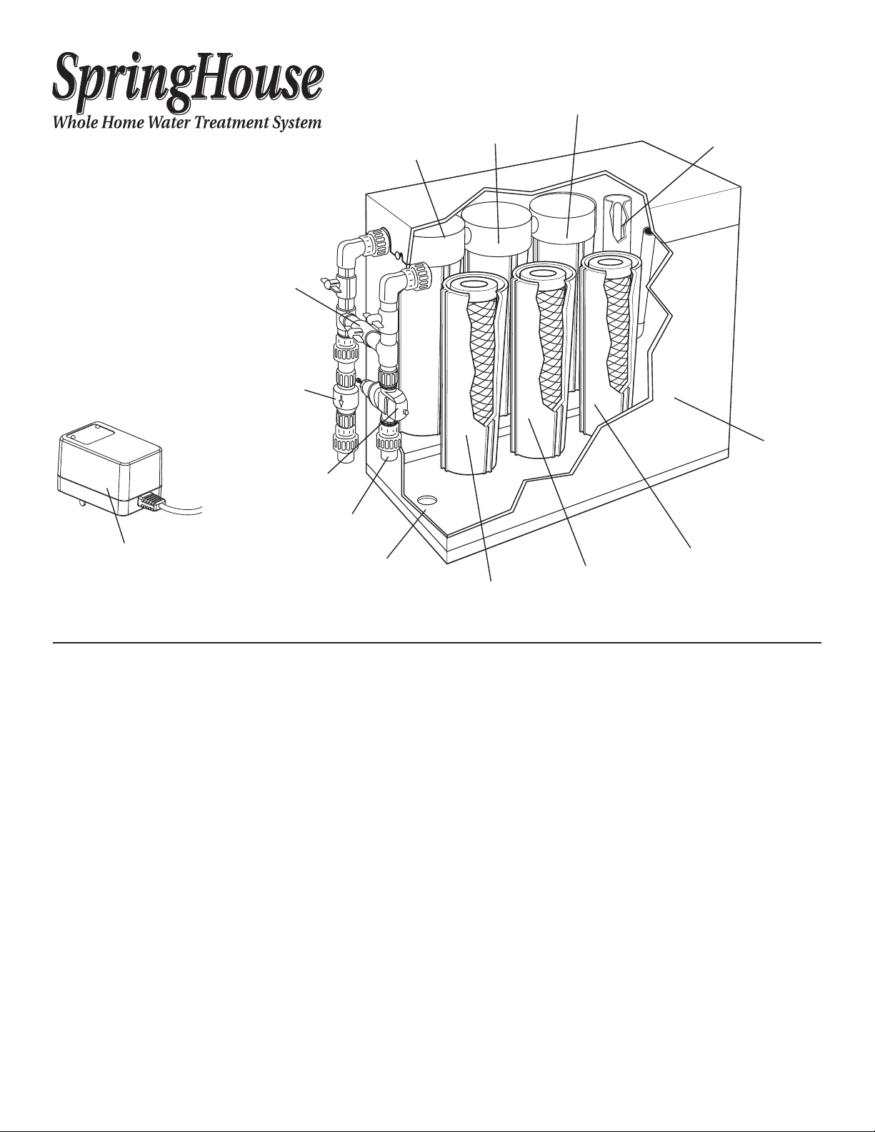
Bypass Valve
#7 Filter
Canister
#6 Filter
Canister
#5 Filter
Canister
#4 Disinfecting
Ultraviolet Light
Brushed
Aluminum
Housing
#3 Filter
Canister
#2 Filter
Canister
#1 Filter
Canister
Pressure Regulator
Back Flow Preventer
and Outgoing Water
(connects to
household plumbing)
Drip Pan and Drain
External Wiring
Harness With
Audible And Visual Alert
Incoming Water

3
CONTENTS:
READPRIORTOINSTALLATION......................................................................................... 2
Specifications.......................................................................................................... 3
PartsOrderingInformation...............................................................................................3
BallastSpecifications ....................................................................................................4
UnpackingInstructions/PreInstallation/Inspection ....................................................................... 4
ProcessDescription......................................................................................................5
InstallationNotes....................................................................................................... 6
OperationandMaintenance ........................................................................................... 10
ReplacingFilterCartridges ..............................................................................................11
Troubleshooting........................................................................................................12
WarrantyInformation...................................................................................................15
PartNumbers......................................................................................................... 16
Please record the serial number of your SpringHouse:
Serial # _________________________________________________________________
Please record the serial number of your optional SpringHouse Remote Alarm (If applicable):
Serial # _________________________________________________________________
Please record the name and phone of your SpringHouse Independent Business Owner:
Name __________________________________________________________________
Phone__________________________________________________________________
SPRINGHOUSE SPECIFICATIONS
MaximumFlowRate...................................................................................... 8G.P.M.@60psi
Dimensions............................................................................................41"Lx16"Wx40"H
Inlet/OutletPipe ...................................................................................1-inchschedule80PVC
OperatingTemperatureRange.................................................................. 35to100degreesFahrenheit
InletPressureRange.......................................................................................... 25to60psi*
OperatingSupplyPressureRange .............................................................................. 25to250psi
Warranty ......................................................................................... 2Yearspartsandlabor**
MicronRating..........................................................................................1micron(absolute)
Audible and visual alarm to monitor UV lamp operation
Back flow Preventer
All filter canisters are FDA compliant.
* Pressure Regulator Preset to 60 psi. Supplying pressures below 40 psi will result in a noticeable reduction in flow through the SpringHouse.
** See page 15 for more information on your Warranty.
PARTS ORDERING INFORMATION
Replacement filter cartridges, filter media, and parts are available by contacting your EcoQuest SpringHouse Independent Business Owner
located on this page. If you do not have their information, please call 1.800.989.2299 for ordering information.

4
BALLAST SPECIFICATIONS
InputVoltage(Nominal) ........................................................................ 120V/60Hz0.7A(45wmax.)
MaximumAllowableHumidity.........................................................................................90%
BallastPowerFactor .................................................................................................. 0.61
TotalHarmonicDistortion........................................................................................... 82.2%
OperatingFrequency ............................................................................................ 36-40Khz
MaxLampCurrent(Within10Sec.) ................................................................................. 425mA
LampCurrentCrestFactor ............................................................................................ 4.38
MaxInternalTemperature,ThermalProtection................................................................... 95°C/120°F
MaxSurfaceTemperature ...................................................................................... 65°C/150°F
Secondary Open Circuit Protection (Lamp Dead Shutdown) . . . . . . . . . . . . . . . . . . . . . . . . . . . . . . . . . . . . . . . . . . . . . . . . . . . . . . . . Yes/Alarm
SecondaryShortCircuitProtection......................................................................................Yes
PowerOnLED ........................................................................................................Yes
LampOnLED.........................................................................................................Yes
AudibleAlarm(LampFault) .......................................................................................... 75db
WireHarness(600V/105°CUL)................................................................................... 10'-4Wire
Assembly.............................................................................................. FullyEncapsulated
UNPACKING INSTRUCTIONS/PREINSTALLATION/INSPECTION
1. Remove outer carton and packaging materials.
2. Inspect filter canisters for cracks and make sure they are securely tightened.
3. Remove UV Chamber Plug Cap (located atop UV chamber) by pulling upwards.
4. Remove UV Chamber retainer fitting by turning counter clockwise.
5. Locate the shipping tube containing the UV Lamp, glass lamp sleeve, spring, nylon washer, and rubber O-ring.
Caution, handle UV lamp and sleeve carefully to avoid breakage.
6. Lubricate the top inch of the outside of the lamp sleeve with either vegetable oil or some type of ingestible lubricant to allow O-ring and
washer to slide. Failure to do so may cause sleeve to break.
7. Slide spring into lamp sleeve and first place O-ring, then nylon washer, over the open end of lamp sleeve. Position them 3/8"-1/2” from
top. Insert glass lamp sleeve (open end up) into UV chamber.
8. Replace retainer fitting and tighten while holding glass sleeve with finger.
9. Insert lamp slowly, with plug connectors up through opening in retainer fitting.
10. Connect bulb to plug cap (See Figure 5*) and push cap down over retainer fitting.
* plug connector configuration may vary.

5
PROCESS DESCRIPTION (REFER TO ILLUSTRATION BELOW)
NOTE: System should be installed by a licensed plumber and protected from freezing or excessive heat to avoid damage and voiding of
Warranty. Be sure you have read system information starting on page 2 before proceeding further!
Back flow Preventer
Outgoing clean, fresh,
great-tasting Living Water
Bypass Valve
Pressure
Regulator
Incoming
Water
#7 Filter
Canister
#6 Filter
Canister
#5 Filter
Canister
#4 Disinfecting
Ultraviolet Light
#3 Filter
Canister
#2 Filter
Canister
#1 Filter
Canister
Outlet Valve Inlet Valve
On Site Well Source Water
Step 1: 5-Micron, dual-gradient particulate filter
Step 2: MAZ filter
Step 3: Carbon Block filter
Step 4: High intensity UV chamber
Step 5: KDF Media filter
Step 6: Anti-scalent/sequestering agent (polyphosphate)*
Step 7: 1-micron filter (absolute) particulate filter
Municipal Source Water
Step 1: 5-Micron, dual-gradient particulate filter
Step 2: Carbon Block filter
Step 3: Carbon Block filter
Step 4: High intensity UV chamber
Step 5: MAZ filter
Step 6: Anti-scalent/sequestering agent (polyphosphate)*
Step 7: 1-micron filter (absolute) particulate filter
* Specialty filters are available for treatment of unique contaminants. These are normally installed in place of the sequestering agent in canister #6.
Ask your Independent Business Owner for details.
Additional Information
Filter life varies with all filters because of broad variations in the quality and quantity of particulate and chemical material found in water
supplies. Realistically, a useful life of up to 1 year can be expected in applications served by municipal water. Indications that one or more
of the filters are reaching the end of their useful life include:
• A noticeable reduction in flow rate through the SpringHouse.
• A noticeable change in the taste of the water.
Failure to change filter or to perform necessary maintenance in accordance with recommendations contained in this manual could result
in diminished performance and reduced water treatment.
Operating the SpringHouse without all filters installed as recommended could adversely affect the treatment performance of the unit. Call
Tech Support (423.798.6700) prior to modifying filter configuration.

6
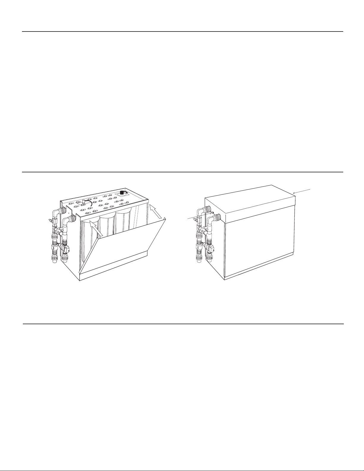
INSTALLATION NOTES
PRELIMINARY MEASURES
1
1. Place the unit in the location of installation.
2
2. Remove top cover by loosening thumb screws and
pulling upward in a straight motion. Set the top
aside. Remove side panel which is attached with
hook & loop tape. Grasping the edges on both
ends, pull outward tipping top toward you.
You may remove both sides for best access if
space allows.
3
3. Carefully remove the carton located in the base of
the unit. This carton contains the ultraviolet light
and quartz sleeve.
4
4. Carefully unwrap the valve assembly and
connect it to the unit using the two unions as
shown in the accompanying diagram. Make sure
all unions are snug and free of “play.”
5
5. Plumb the unit into the water service line using the
unions provided paying close attention to the inlet
and outlet.
/"1//
GENERAL
PRECAUTIONS:
• Installation must be done
by a qualified plumber in
accordance with local codes.
Failure to do so can result
in damage not covered by
your SpringHouse warranty.
Installation by a licensed
plumber is recommended.
• SpringHouse can be installed
outdoors but must be
protected from freezing,
excessive heat and direct
sunlight. Failure to do so can
result in component failure,
water leakage, and/or
property damage and will
void the warranty.
• Install on cold water
lines only.
• Install after the
pressure regulator.
• Install after any pressure
tanks or other water treatment
equipment such as softeners.
• Flow must be in the direction
indicated on the canister tops.
• When installing unit, be sure
to position it for easy access
to the filter canisters for
maintenance purposes.
• Unit must be located
within 6 feet of a
110v - 120v gfci outlet.
• Inlet and outlet plumbing
1 inch.
• Maximum supply pressure
250 psi.
• Operating temperature range
of 35-100 degrees Fahrenheit.
• Rated service flow of up to
8 g.p.m. The use of reducers
and/or excessive fittings can
result in a decreased flow
rate and is not recommended.
Household water pressures
of less than 40 psi will result
in a noticeable reduction in
flow rate.
7
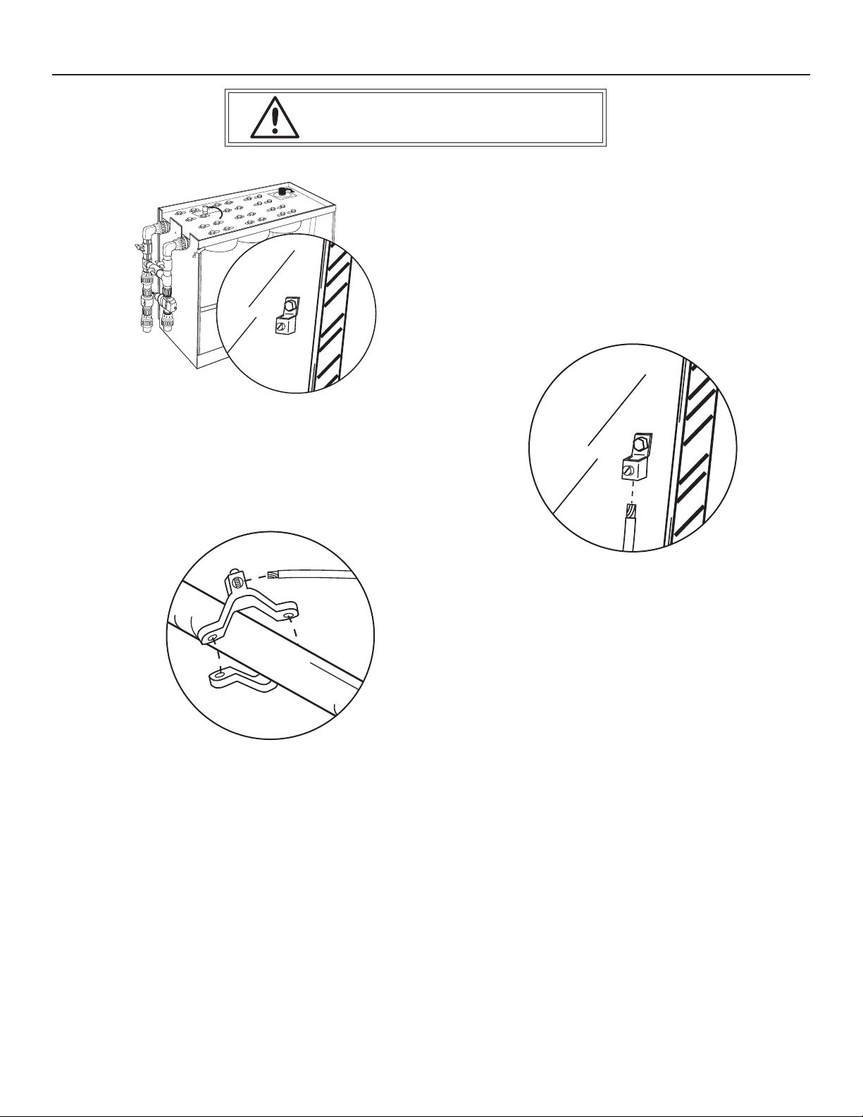
1
1. Locate the Grounding Lug on the plumbing side
of SpringHouse to be used for grounding.
GROUNDING THE UNIT
2
2. Insert provided grounding wire into Grounding
Lug connection point and tighten clamp screw.
3
3. Attach opposite end of grounding wire to a
proper household ground. Provided Grounding
Clamp to be used metallic plumbing entering
facility.
CAUTION: failure to properly ground the unit could lead
to serious injury or death.
8
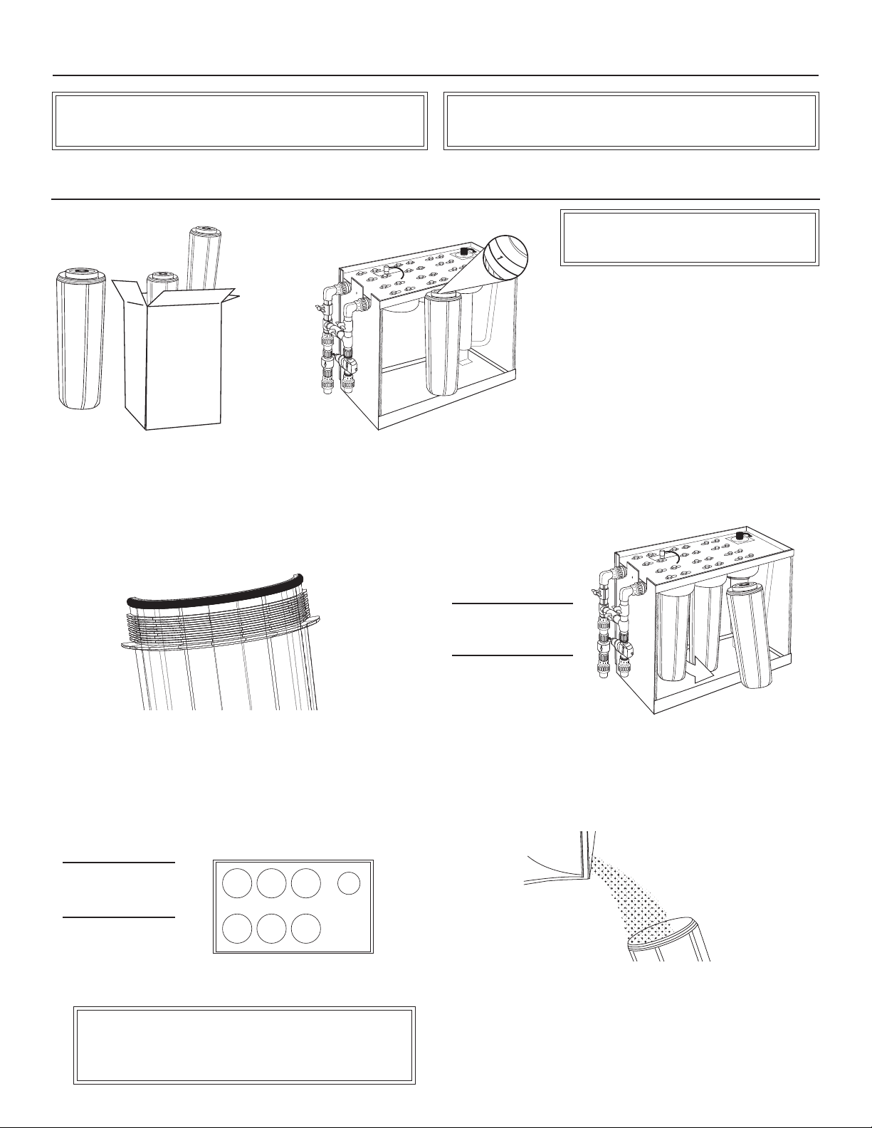
ASSEMBLING YOUR SPRINGHOUSE FILTERS
WASH HANDS THOROUGHLY AND FREQUENTLY WHILE HANDLING FILTER
CARTRIDGES TO AVOID CONTAMINATING THE CARTRIDGES.
WORK WITH ONLY ONE FILTER CANISTER AT A TIME TO AVOID
MIXING UP THE FILTERS. DO NOT OVER TIGHTEN THE CANISTER.
FILTER CANISTER INSTALLATION
3
3. Wash the inside of the canister using hot
water and a small amount of household
dish washing detergent (automatic dish
washing detergent is best).
Rinse the canister thoroughly using clean
water until all soap residue is removed.
Remove the protective plastic from the filter
which should be marked with the number 1
and place it in the housing.
1
1. Remove the blue filter canisters
(containing the filters) from the boxes.
4
4. Apply a light coat of food-grade lubricant (such as silicone gel) to
the surface of the black O-ring at the top of the housing. This step
is very important and cannot be skipped for any reason.
2
2. Each blue filter canister, black canister cap
(on the unit) and filter is numbered. Take
filter canister #1, remove the filter from the
canister and set aside.
CAUTION:
Do not over tighten
canisters when installing.
5
5. Being careful to match the number on the blue canister with the
number on the black canister head, carefully screw the blue canister
into the black portion of the filter canister. Hand tighten the canister.
Snug with supplied wrench. DO NOT overtighten canisters.
NOTE: FILTER PACKING MUST BE
REMOVED BEFORE INSTALLATION.
6
6. Repeat the installation process, in-turn, for canisters 2, 3, 5, and 7.
Container 6 will contain the polyphosphate granules, see step 7.
NOTE: When a new Carbon or KDF filter is installed, it is strongly
recommended that the 1-micron filter (canister #7) not be installed until
the system is fully flushed as described in item 21 under "Replacing Filter
Cartridges" (page 10). This will prevent premature clogging of the filter.
NOTE: Canister 4
is for the UV lamp.
(See next page)
£ÓÎÇÈx{
7
7. For canister 6, clean as recommended for canisters 1, 2, 3, 5,
and 7. Open the bag of polyphosphate granules and pour them
into the canister. Install the canister.
9
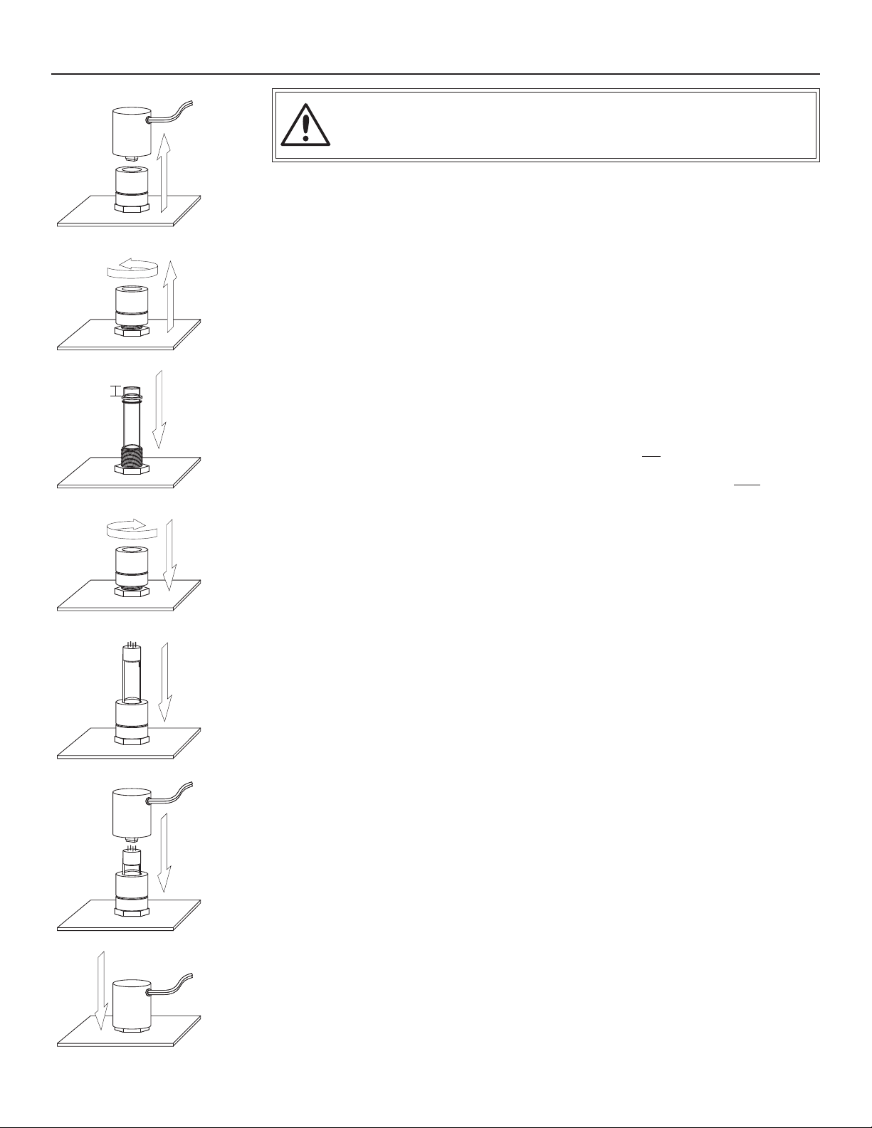
ULTRAVIOLET (UV) LAMP AND SLEEVE ASSEMBLY
1
1. Locate canister number 4 (shown on previous page).
With the plastic cover removed, remove the threaded
retainer on the top of the ultraviolet (UV) canister. (See
figure 1 & 2).
2
2. Open the carton containing the UV lamp and
the quartz sleeve. Remove the quartz sleeve
from its packing. (Be sure not to remove UV bulb
from packing yet).
5
5. Place the threaded retainer over the top of the sleeve
and gently tighten the cap until it is snug and the top of
the sleeve is properly seated in the cap. Do not over-
tighten as the sleeve may break (See figure 4).
6
6. Check the seat at the top of the sleeve by
reaching into the middle of the retainer and
rubbing a finger along the inside of the glass.
There should be a slight gap between the glass
and the cap. If an uneven gap is present, do
not attempt to tighten the cap further as the
sleeve will break. The uneven gap indicates
that the sleeve is misaligned. STOP and repeat
step #3 taking care to insure proper seating and
alignment of the sleeve.
7
7. Remove the UV lamp from the packing and clean
thoroughly with rubbing alcohol to remove all traces
of oil and grease. Be careful not to touch the glass
lamp area with your fingers as this will leave oils on
the lamp, causing the lamp to fail prematurely.
8
8. Carefully slide the UV lamp through the
retainer and into the quartz sleeve making
sure that the lamp prongs are at the top
(See figure 5).
9
9. Plug the ballast into the top of the UV lamp
(See figure 6).
10
10. Place the plastic cover over the retainer to
protect the top to the UV lamp. The lamp should
be seated low enough in the sleeve so that when
the plastic cover is in place, there is clearance
between it and the cabinet top (See figure 7).
Plug ballast into properly grounded 110-120 Volt
household receptacle.
3
3. The quartz sleeve resembles a large test tube.
Remove the sleeve from the packing and place it
into the top of the UV canister and carefully lower it
into place. Be sure the sleeve is straight and slides
fully into the receiving tube at the bottom of the
canister. The sleeve will be fitted with a black O-ring
and a plastic washer near the top. These should be
positioned about 1/2 inch from the top of the tube.
All water should be removed from the canister before
proceeding with this step (See figure 3).
4
4. Check that the bottom of the sleeve is seated
properly by gently depressing the top edge
of the sleeve with a finger. The sleeve should
bounce on the spring located in the receiving
tube. If it does not bounce the tube is misaligned
and must be re-seated BEFORE proceeding.
Apply a very thin coat of unscented petroleum
jelly to the top rim of the sleeve. Be careful not
to get any of the jelly on the inside of the sleeve.
figure 1
figure 2
figure 7
figure 6
figure 5
figure 4
figure 3
WARNING: THE SLEEVE IS FRAGILE. ROUGH HANDLING OR MISALIGNMENT WILL CAUSE IT TO BREAK.
CAUTION - SHOCK HAZARD: BE SURE UNIT IS PROPERLY GROUNDED (SEE PAGE 7) AND AREA
IS FREE OF STANDING WATER BEFORE PLUGGING UNIT INTO RECEPTACLE.
1/2”
10
CHARGE THE SYSTEM
Turn on water:
1. Uncoil clear tubing attached to pressure relief valve on top of unit, and place end of tube into bucket or drain. Open pressure relief valve.
2. Gradually turn on water to unit being careful to secure the plastic hose into a bucket or drain.
3. Allow unit to fill until a steady stream of water is flowing from the bypass valve tubing and all air has been purged from the system. Close
pressure relief valve.
4. Check unions on valve assembly.
5. Check filter canisters for leaks.
6. Check around the top of UV lamp fittings for leakage.
7. Flush system as per item 19 in section “Replacing Filter Cartridges” (page 11).
If you see any water leaking from any of the mentioned locations, tighten slightly until leak has stopped. Side panels and top cover may be
kept off for a period of time in order to watch for any leaking following initial pressurization.
REASSEMBLY
2
3. Lower cover into place. Tighten thumb screws.
1
1. Replace side panels with hook & loop tape.
OPERATION AND MAINTENANCE
NOTICE: UNPLUG SYSTEM BEFORE PERFORMING ANY OF THE MAINTENANCE PROCEDURES LISTED!
To open the inlet, outlet, or bypass valve: Turn handle in a counter clockwise direction. To close turn in a clockwise direction.
NOTE: Handle will only rotate 1/4 turn. Bypass valve should be closed when inlet/outlet valves are open for normal operation.
1. UV Diagnostic System: Audible and visual alarm on ballast. Red indicates lamp or electronics system failure.
2. Frequency of maintenance - NOTE: Filter and/or life varies depending on quality of water supply. See page 16 for parts ordering
information and order numbers.
• 5-micron filter: Replace annually, check for sediment semiannually.
• UV lamp: Replace annually.
• Polyphosphate: Refill semiannually or when crystals have been mostly dissolved.
• MAZ filter, KDF filter, carbon block, and 1-Micron filter: Check every 6 months and replace if necessary.
Filters should be replaced at least once a year to insure proper water treatment.

11
Replacing filter cartridges (canisters #1,2,3,5, & 7), ultraviolet light
(canister #4), or polyphosphate crystals (canister #6)
1. Remove cover and unit housing following instructions on page 6,
Step 2.
2. Uncoil clear tubing attached to pressure relief valve on top of
unit and place end of tube into bucket or drain.
3. Open bypass valve (see illustration page 5).
4. Close inlet valve and outlet valve (see illustration page 5).
5. Open pressure relief valve (be sure tube is secured in bucket or
drain). Leave pressure relief valve open.
6. Unscrew blue canister counter clockwise using supplied canister
wrench.
7. For canisters 1, 2, 3, 5, 6, & 7, remove used cartridge/crystals
and discard.
8. CAUTION: Confirm system is disconnected from power source
before proceeding with step 8!
On canister #4, pull up on plug cap (see page 9 - figure 1) until
lamp is exposed. Unplug lamp, from plug cap. Remove old lamp
from chamber and insert new lamp with connectors pointing up.
Plug lamp into plug cap and place cap back over top.
10. Rinse out each canister and fill about 1/3 full of water.
Add 2 tablespoons of bleach and scrub thoroughly with a
fine bristle brush or cloth. Let blue canister remain wetted
with bleach solution for 5-10 minutes. Empty canisters and
rinse thoroughly.
11. Insert a new cartridge into the canisters or refill
polyphosphate crystals as required.
EXCEPTION-See #19 below before proceeding.
12. Screw the blue canister into the cap and HAND tighten.
Gently snug the canister with the supplied wrench. DO NOT
OVER-TIGHTEN.
13. Open inlet valve (see illustration page 5) and be sure tube is
secured in bucket or drain.
14. Open outlet valve (see illustration page 5).
15. Close bypass valve (see illustration page 5).
16. Observe tubing to determine that all air has escaped the unit.
17. Close pressure relief valve and coil tubing on top of unit.
18. Check for leaks before leaving installation.
18. Replace unit housing and cover.
19. Some cartridges may contain a small amount of “fines” (very fine
black powder). Following the installation of new filter cartridges,
the system should be sufficiently flushed to remove these “fines”
before using the water. Important: Run one faucet in the home
for 20 minutes after the installation of any new filter.
The 1-micron filter should be left out of canister 7 until the unit
has been flushed to prevent pre-mature clogging of the filter.
REPLACING FILTER CARTRIDGES
On Site Well Source Water
Step 1: 5-Micron, dual-gradient particulate filter
Step 2: MAZ filter
Step 3: Carbon Block filter
Step 4: High intensity UV chamber
Step 5: KDF Media filter
Step 6: Anti-scalent/sequestering agent (polyphosphate)*
Step 7: 1-micron filter (absolute) particulate filter
Municipal Source Water
Step 1: 5-Micron, dual-gradient particulate filter
Step 2: Carbon Block filter
Step 3: Carbon Block filter
Step 4: High intensity UV chamber
Step 5: MAZ filter
Step 6: Anti-scalent/sequestering agent (polyphosphate)*
Step 7: 1-micron filter (absolute) particulate filter
£ÓÎÇÈx{
CAUTION - SHOCK HAZARD: BE SURE UNIT IS UNPLUGGED BEFORE PROCEEDING WITH FILTER REPLACEMENT.
CAUTION - SHOCK HAZARD: BE SURE AREA IS FREE OF STANDING WATER BEFORE PLUGGING UNIT INTO RECEPTACLE.
* Specialty filters are available for treatment of unique contaminants. These are normally installed in place of the sequestering agent in canister #6.
Ask your Independent Business Owner for details.

12
Sudden or Very Rapid Decrease in Observed Flow Rate
Possible Causes:
1.Substantial Drop in Pressure of Feed Water
2.Inlet or Outlet Valve on SpringHouse Partially Closed
3.Obstruction Within the SpringHouse
4.Blockage in check valve
Actions: (complete in order until problem is isolated)
CAUTION - SHOCK HAZARD: Be sure unit is unplugged before
proceeding with any step.
1.Check to make sure that both the inlet and outlet valves on the
SpringHouse unit are in the fully opened position.
2.Close inlet and outlet valves to SpringHouse unit. Open bypass
valve. Is full flow restored? If yes, problem resides with the
SpringHouse, if no, problem resides with the water system
supplying the SpringHouse or the back flow check valve on
the valve assembly.
3.Remove back flow check valve and check for proper alignment
and operation. If unit is operating correctly, problem resides with
water system supplying the SpringHouse unit. If back flow check
valve is operational and full flow is achieved in bypass mode,
proceed to step 4.
4.Turn off the water supply to the SpringHouse, leave the bypass
closed and open a faucet. This will bleed off the pressure in the
system. Under certain extreme conditions, turbulence in the
SpringHouse may mobilize some of the polyphosphate crystals in
the outlet of canister #6. These crystals could become lodged in
the outlet of the filter. Relieving the pressure on the system would
have allowed them to fall back into the bottom of the canister,
once again opening the restriction. Repressurize the unit then
open the supply line to household plumbing system. If full flow is
not restored, proceed to next step.
5.Turn off the water supply to the SpringHouse, leave the bypass
closed and relieve pressure using the pressure relief valve on
the unit (on those units where the valves are operational) or by
opening a faucet. This will bleed off the pressure in the system.
Carefully remove canister #6. Inspect for floating debris on the
surface of the water PRIOR to emptying the canister. If no debris
is evident, SLOWLY pour out the water in the canister while
inspecting for presence of any debris. Once emptied of water, set
the canister aside. Reach into the outlet side of the canister head
(this is the hole in the middle) and probe to identify if the outlet
orifice is plugged. If it is, remove material, replace canister and
repressurize unit. If full flow is not restored, repeat the procedure
with canisters 1, 2, 3, 5, and 7.
6.If full flow is still not restored, it is likely that a filter is clogged
or faulty. Refer to page 11 regarding the changing of filters.
Gradual Reduction In Flow Volume or Pressure
Possible Causes:
1.Water pressure to the house from the source has been reduced
2.One or more filter cartridges in the SpringHouse unit are clogging
or otherwise reaching the end of their useful life
Actions: (complete in order until problem is isolated)
CAUTION - SHOCK HAZARD: Be sure unit is unplugged before
proceeding with any step.
1.Check to make sure that both the inlet and outlet valves on the
SpringHouse unit are in the fully opened position.
2.Close inlet and outlet valves to SpringHouse unit. Open bypass
valve. Is full flow restored? If yes, problem resides with the
SpringHouse, if no, problem resides with the water system
supplying the SpringHouse.
3.Turn off the water supply to the SpringHouse, leave the bypass
closed. Bleed pressure in the system by opening a faucet or the
pressure relief valve on the unit itself. Close the outlet valve. Wash
hands. Carefully remove canister #7 and take out the 1-micron
filter, placing it in a clean plastic garbage bag. Replace canister #7
WITHOUT the filter, being careful to lubricate the O-rings with a
suitable food-grade silicone. Open the outlet valve and then the
inlet valve to the SpringHouse allowing the unit to repressurize.
Check to determine if full flow through the SpringHouse unit has
been restored. If it has, you have isolated the clogged filter and
can proceed to install a new one. If flow has not been restored
you must check the remaining canisters, each in turn.
4.Canister #6 contains loose polyphosphate crystals. Refer to
“Sudden or Very Rapid Decrease In Observed Flow Rate” steps 4,
5, and 6 to check this canister.
5.Without returning the filter cartridge to canister #7, repeat the
procedure outlined in #3 above for canisters 5, 3, 2, and 1 being
sure to check each in turn until the clogged filter is identified.
DO NOT MIX UP THE CARTRIDGES AS THOSE THAT ARE NOT
CLOGGED MUST BE REINSTALLED IN THEIR
ORIGINAL CANISTERS.
6.Once you have identified the clogged filter and replaced it,
replace the previously removed filters to their original canisters.
Turn on the water supply to the SpringHouse by opening the inlet
valve. Leave the bypass closed and open the outlet valve. Open a
faucet to bleed the air from the system and check to insure that
full flow is restored through the SpringHouse.
TROUBLESHOOTING

13
INSTALLATION NOTES:

14
INSTALLATION NOTES:

15
WARRANTY INFORMATION
Limited Two (2) Year Warranty
EcoQuest International warrants to the original purchaser that each SpringHouse will be free from defects in material and workmanship
under normal usage for two (2) years from the date of original shipment of the unit. In the event that such defects become evident during
the warranty period, EcoQuest will, at its option, replace or repair the product without charge to you. This warranty does not include
transportation nor insurance charges for the product. All warranty work must be performed by EcoQuest International or by an authorized
service provider. This warranty will not cover repairs performed by other than EcoQuest authorized service providers unless expressly
otherwise agreed by EcoQuest, in writing.
Limited One (1) Year Warranty on Filters and Lamps
The filters and ultraviolet lamp which are included with your original purchase are considered replacement items. These items have limited
lives and the purchaser understands that they will require periodic replacement. EcoQuest International warrants to the original purchaser
that each filter and ultraviolet lamp will be free from defects in material and workmanship under normal usage for a period of one (1) year
from the date of original shipment. In the event that such defects become evident during the warranty period, EcoQuest will, at its option,
replace or repair the item without charge. The warranty for replacement filters and ultraviolet lamps does not include normal consumption
or usage of the filters and lamps.
Warranty Limitation
Installation of this unit on other than a potable water system will immediately and completely void the warranty. The warranty is also
voided and provides no coverage where the damage results from improper installation, alterations, abuse, or misuse as determined by
EcoQuest International.
ALL WARRANTIES IMPLIED BY STATE LAW INCLUDING THE IMPLIED WARRANTIES OF MERCHANTABILITY AND FITNESS FOR A
PARTICULAR PURPOSE ARE EXPRESSLY DISCLAIMED IN LIEU OF THE LIMITED WARRANTY SET FORTH ABOVE.
Some states do not allow limitations on how long an implied warranty lasts so the above limitation may not apply to you.
THE FOREGOING EXPRESS WARRANTY IS EXCLUSIVE AND IN LIEU OF ALL OTHER WARRANTIES, GUARANTEES, AGREEMENTS, AND
SIMILAR OBLIGATIONS OF THE MANUFACTURER OR SELLER WITH RESPECT TO THE REPAIR OR REPLACEMENT OF ANY PRODUCT
OR PARTS, WHETHER EXPRESSED OR IMPLIED.
IN NO EVENT SHALL THE MANUFACTURER OR SELLER BE LIABLE FOR CONSEQUENTIAL OR INCIDENTAL DAMAGES.
Some states do not allow the exclusion or limitation of incidental or consequential damages so the above limitation may not apply to you.
These warranties are given in lieu of any other warranties, expressed or implied. No person, agent, distributor, dealer, service station, or
company is authorized to change, modify, or extend the terms of this warranty in any manner whatsoever.
How to Obtain Warranty Service
For warranty service, call 1.800.989.2299 and ask for warranty claims or write to the address provided below. Parts returned to EcoQuest
International under this warranty must be shipped to the following address postpaid:
EcoQuest International
310 T. Elmer Cox Drive
Greeneville, TN 37743
65-00008-005
Rev. 0906
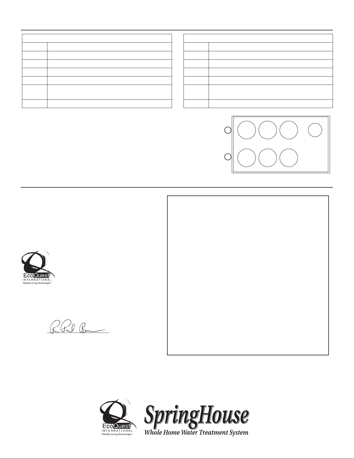
PART NUMBERS
Name: EcoQuest
Model: SpringHouse
Manufacturer: EcoQuest Manufacturing
This device complies with Part 18 of the FCC Rules.
RESPONSIBLE PARTY
EcoQuest International
310 T. Elmer Cox Drive
Greeneville, TN 37743
Ph: (800) 989-2299
Signature:___________________________
Printed Name: Paul Beam
Title: Director of Engineering
Date: 8/8/05
This equipment has been tested and found to comply with the limits for
Industrial, Scientific, and Medical Equipment (ISM), pursuant to Part 18 of
the FCC Rules. These limits are designed to provide reasonable protection
against harmful interference in a residential installation. This equipment
generates, uses, and can radiate radio frequency energy, and if not
installed and used in accordance with the instructions, may cause harmful
interference to radio communications. However, there is no guarantee that
interference will not occur in a particular installation. If this equipment does
cause harmful interference to radio or television, which can be determined by
turning the equipment off and on, the user is encouraged to try to correct the
interference by one or more of the following measures:
Reorient or relocate the receiving antenna.
Increase the separation between the equipment and receiver.
Connect the equipment into an outlet on a circuit different from that to
which the receiver is connected.
Consult the Independent Business Owner or an experienced radio/TV
technician for help.
FCC DECLARATION OF CONFORMITY
EcoQuest™, Healthy Living Technologies™, SpringHouse™, are Trademarked by EcoQuest™International.
EcoQuest International “Healthy Living Technologies”®is Registered by EcoQuest™International.
On Site Well Source Water
Step 1: 5-Micron, dual-gradient particulate filter US70940
Step 2: MAZ filter US70237
Step 3: Carbon Block filter US70793
Step 4: High intensity UV chamber US70235
Step 5: KDF Media filter US70238
Step 6: Anti-scalent/sequestering agent (polyphosphate)*
US70242
Step 7: 1-micron filter (absolute) particulate filter US70241
Municipal Source Water
Step 1: 5-Micron, dual-gradient particulate filter US70940
Step 2: Carbon Block filter US70793
Step 3: Carbon Block filter US70793
Step 4: High intensity UV chamber US70235
Step 5: MAZ filter US70237
Step 6: Anti-scalent/sequestering agent (polyphosphate)*
US70242
Step 7: 1-micron filter (absolute) particulate filter US70241
* Specialty filters are available for treatment of unique contaminants. These are normally installed in place
of the sequestering agent in canister #6. Ask your Independent Business Owner for details.
£ÓÎÇÈx{
Top view, valve assembly on left.
Table of contents
Popular Water System manuals by other brands


Elkay
Elkay EZH20 Series Installation, care & use manual

AmeriWater
AmeriWater MRO3 Operation & maintenance manual

FAFCO
FAFCO 500 Series installation manual

DAB
DAB GENIX Instruction for installation and maintenance

EcoWater
EcoWater ES9120R owner's manual

AquaLiv
AquaLiv A500 Usage & installation instructions

Kenmore
Kenmore Elite ULTRAFILTER 650 625.38556 owner's manual

Everpure
Everpure Quad-MC EV9628-08 Specification sheet

Grunbeck
Grunbeck desaliQ Operation manual

Scheppach
Scheppach HWW1300 Translation of original instruction manual

Wave Home Solutions
Wave Home Solutions HYDROCARE DUAL ACTION installation manual

EcoWater
EcoWater ESM Series instructions