Meg Trident Series User manual

MEG Trident Series
Personal Computer
Trident B922
Service Guide

2Contents
Contents
How to Use this Service Guide..................................................................................... 3
Necessary Tools ........................................................................................................... 3
Safety Instructions........................................................................................................ 3
Other Notice.................................................................................................................. 4
Upgrade and Warranty................................................................................................. 4
Acquisition of Replaceable Parts ................................................................................ 4
Removing Side Covers ................................................................................................. 5
Right Side View ............................................................................................................. 6
Left Side View................................................................................................................ 6
Removing CPU Cooler Set........................................................................................... 7
Removing CPU.............................................................................................................. 8
Removing Memory ....................................................................................................... 9
Removing M.2 SSD (Optional).................................................................................... 10
Removing Graphics Card........................................................................................... 12
Installing 3.5” HDD (Optional).................................................................................... 16
Revision
V1.0, 2022/11

3
How to Use this Service Guide
How to Use this Service Guide
This Service Guide is designed for MSI-authorized dealers or service centers. It
provides in-depth illustration of disassembling/assembling the system. Since the
topics in this guide may be related, it is recommended that you read it from cover to
cover first. After that, you may go directly to any specific topic that most meets your
immediate needs.
⚠
Important
All information is subject to change without prior notice. The system photos are
provided for demonstration only. The internal view of your system may vary depending
on the model you purchased.
Necessary Tools
Screwdriver Pliers Tweezers Anti-Static Gloves
Safety Instructions
The following precautions should be observed while handling the product. It is always
suggested that users contact the authorized MSI service center for advanced tech
support if needed.
∙Refer servicing to qualified personnel only.
∙Disconnect all power sources and place the product on a steady surface before
disassembly/reassembly.
∙When unplugging the power cord, always hold the connector part of the cord. Never
pull the cord directly.
∙Do not place the product in environments subject to mist, smoke, vibration,
excessive dust, salty or greasy air, or other corrosive gases and fumes.
∙To avoid electrostatic discharge, use an anti-static wrist strap before handling
components. Always handle electrostatic-sensitive components, parts, and
assemblies only at static-free work areas.
∙Handle components with care. Do not touch the pins or contacts on a component.
∙Place components on a grounded anti-static pad or on the bed that came with the
components whenever the components are separated from the product.
∙Do not perform any maintenance with wet hands.
∙Prevent foreign substances, such as water, other liquids or chemicals, from
entering the product while performing disassembly/reassembly.

4Other Notice
∙After reassembly, ensure that all screws are replaced and no stray screws remain
inside the product.
∙If this product comes with an adapter, use only the MSI provided AC adapter
approved for use with this product.
Other Notice
The peripheral devices contained herein may vary depending on your actual system
configuration.
Third-party trademarks and names are the properties of their respective owners.
The information contained herein relevant to software and hardware are for reference
only and in accordance with actual system configuration. All information is subject to
change without notice.
Upgrade and Warranty
Please note that certain components preinstalled in the product users purchased
may be upgradable or replaceable by user’s request. To learn more about upgrade
limitation, please refer to the specification in the User Guide. For any further
information about the product users purchased, please contact the local dealer. It is
strongly recommended that you contact the authorized dealer or service center for
any upgrade or replace service.
Acquisition of Replaceable Parts
Please be noticed that the acquisition of replaceable parts (or compatible ones) of
the product users purchased in certain countries or territories may be fulfilled by
the manufacturer within 2 years at most since the product has been discontinued,
depending on the official regulations declared at the time. Please contact the
manufacturer via https://www.msi.com/support/ for the detailed information about
the acquisition of spare parts.

5
Removing Side Covers
Removing Side Covers
⚠
Important
∙
Before you remove or install any components, make sure the system is not turned
on or connected to the power.
∙
Follow the steps below in reverse order to install/replace the component if needed.
1. Place the system on a flat and steady surface.
2. Unlock the cover screws and keep them for later use.
3. Pull to open the covers carefully. Remove them, and set them aside for later use.
6Right Side View
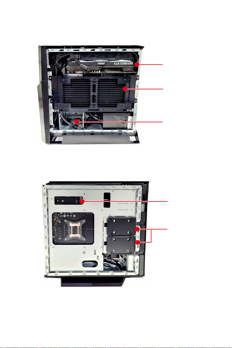
Right Side View
Graphics Card
CPU Cooler,
Motherboard
3.5” HDD
Left Side View
M.2
2.5” HDD
⚠
Important
Reference image only. Appearance will vary.
7
Removing CPU Cooler Set
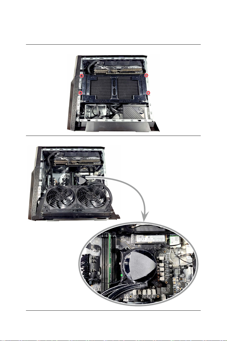
Removing CPU Cooler Set
∙
Follow the steps below in reverse order to install/replace the component if needed.
1. Unscrew the CPU cooler set and set the screws aside for later use.
2. Flip the CPU cooler set outwards to uncover the motherboard.
8Removing CPU
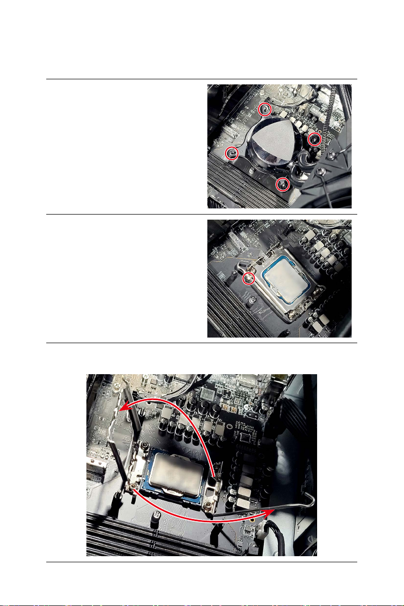
Removing CPU
∙
Follow the steps below in reverse order to install/replace the component if needed.
1. Unscrew and remove the cooler to
uncover the CPU.
2. Open the CPU load lever.
3. Lift the load lever and load plate up to fully open position.
4. Gently remove the CPU from the socket.

9
Removing Memory
Removing Memory
∙
Follow the steps below in reverse order to install/replace the component if needed.
1. Flip the slot clip outwards to release the memory module.
2. Gently remove the memory module from the slot.
10 Removing M.2 SSD (Optional)
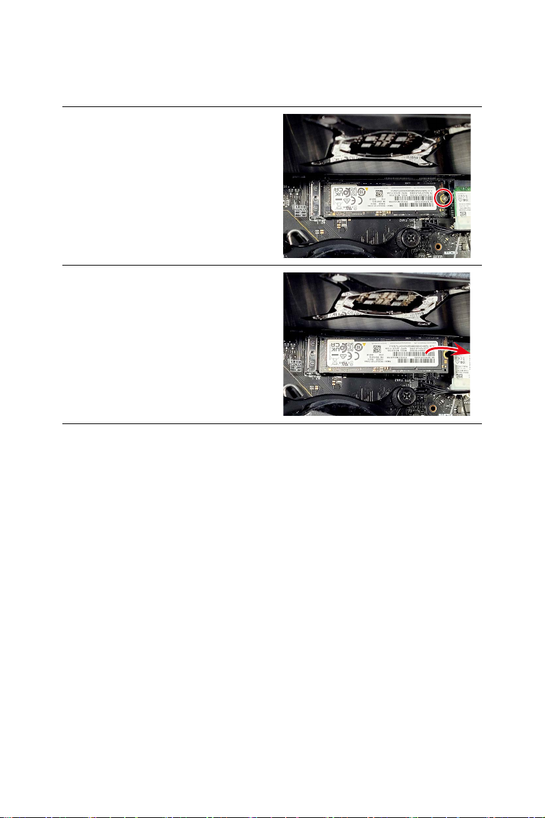
Removing M.2 SSD (Optional)
∙
Follow the steps below in reverse order to install/replace the component if needed.
1. Locate the M.2 SSD and remove the
screw.
2. Gently remove the SSD from the slot.

11
Removing M.2 SSD (Optional)
Removing Wireless Card
∙
Follow the steps below in reverse order to install/replace the component if needed.
1. Remove the wireless card clip.
2. Disconnect the antenna cables and
remove the screw that secures the
wireless card.
3. Remove the wireless card from the
card slot.

12 Removing Graphics Card
Removing Graphics Card
⚠
Important
∙
Reference image only. Graphics card appearance will vary.
∙
Follow the steps below in reverse order to install/replace the component if needed.
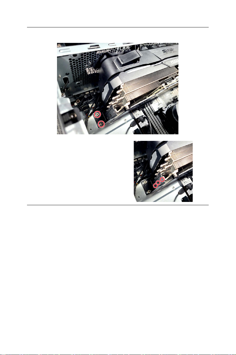
1. Unscrew the system bracket that
secures the graphics card.
2. Flip the system bracket outwards.
3. Remove the screws from the graphics card bracket.
13
Removing Graphics Card
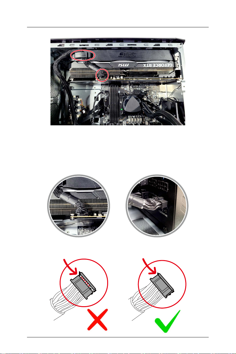
4. Disconnect the graphics card power connector and release the power cable.
⚠
Important
∙
Avoid using any kind of power splitters when powering a GPU.
∙
Before powering on the system, make sure both ends of the GPU power cable
have been fully inserted and fastened to the graphics card’s 12+4 pin PCIe
connector and the PSU’s 12+4 pin slot.
GPU PSU
Not Fully Inserted Fully Inserted
14 Removing Graphics Card
5. Remove the screws from the graphics card support bracket to release the
graphics card.
⚠
Important
To better secure the graphics card to the
motherboard during installation, make
sure that you fasten the support bracket
to the graphics card with screws.

15
Removing Graphics Card
6. Press the PCIE slot clip downwards to unlock the graphics card and
simultaneously pull the graphics card off the PCIE slot.
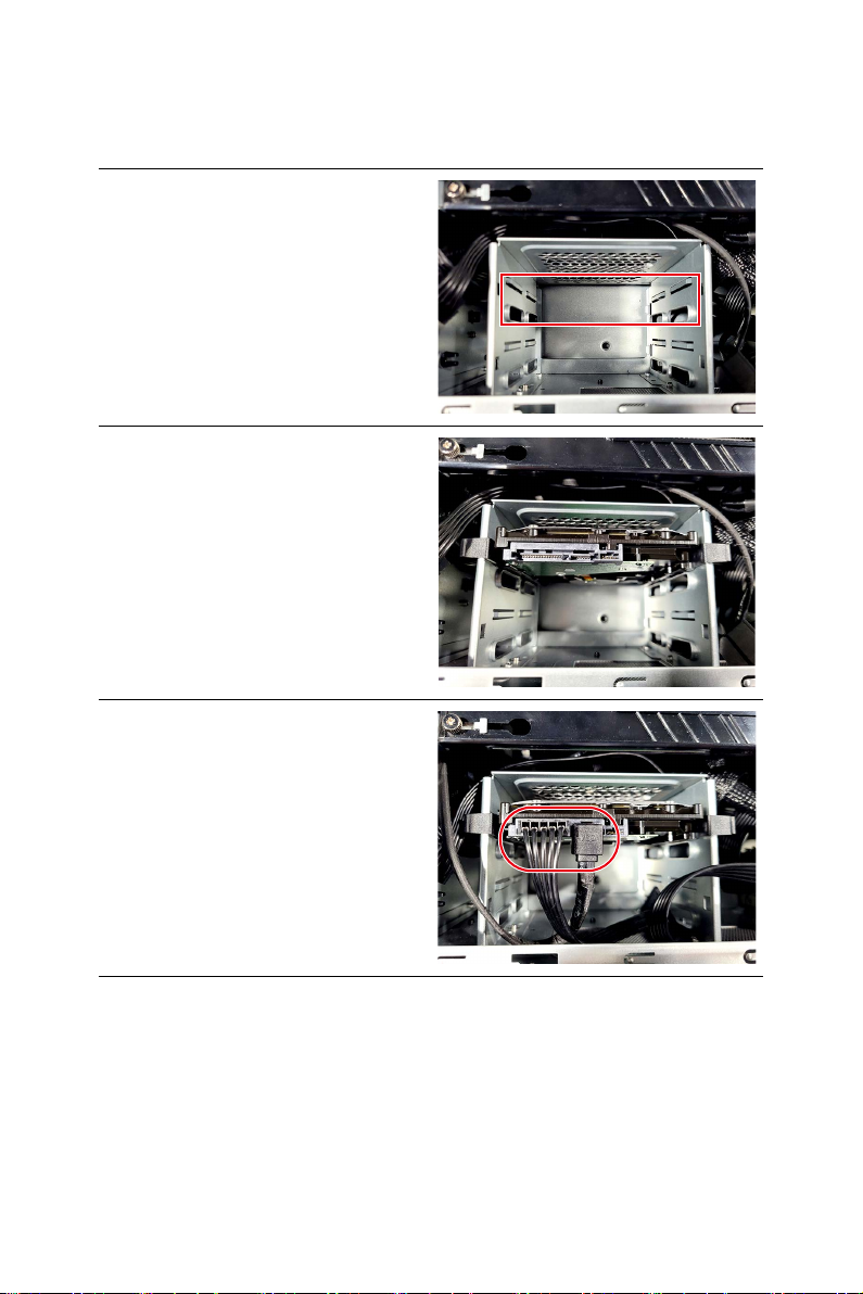
16 Installing 3.5” HDD (Optional)
Installing 3.5” HDD (Optional)
∙
Follow the steps below in reverse order to replace the component if needed.
1. Locate the 3.5” HDD cage.
2. Insert and gently push the HDD into
the cage until it locks in place.
3. Connect the power and signal cables
to the HDD.
This manual suits for next models
1
Table of contents


