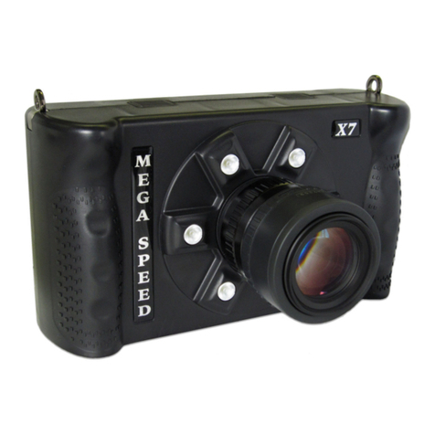
Mega Speed HHC X8 Pro User manual

HHC X8 - X9 Pro
High Speed Camera
With high power LED work lights and SSD option
User Guide
Version 1.03

Contents
1 HHC X8 - X9 Including PRO models Hardware details..................................................................................................... 5
2 HHC Main Camera Menu ................................................................................................................................................ 6
2.1 Start......................................................................................................................................................................... 6
2.2 LED .......................................................................................................................................................................... 6
2.3 Image Size Menu..................................................................................................................................................... 7
2.4 Speed Setting .......................................................................................................................................................... 7
2.5 Exposure Setting ..................................................................................................................................................... 8
2.6 Review Menu .......................................................................................................................................................... 8
2.7 Quicksave RAM to SSD............................................................................................................................................ 8
3 Settings Menu ................................................................................................................................................................. 9
3.1 Trigger Modes Menu............................................................................................................................................... 9
3.2 Sensor Boost Menu (optional) .............................................................................................................................. 12
3.3 USB/SD Menu........................................................................................................................................................ 12
3.4 Camera SSD Streaming (optional)......................................................................................................................... 13
3.5 Standby Mode....................................................................................................................................................... 13
3.6 Power Off .............................................................................................................................................................. 13
4 Sync Settings ................................................................................................................................................................. 14
4.1 Intro....................................................................................................................................................................... 14
4.2 Sync Purpose......................................................................................................................................................... 14
4.3 Sync Configuration –Hardware ............................................................................................................................ 15
4.4 Sync Configuration –Software.............................................................................................................................. 16
4.5 External Sync Sources ........................................................................................................................................... 17
5 Advanced Settings Menu .............................................................................................................................................. 18
5.1 Show Settings........................................................................................................................................................ 18
5.2 Show Status........................................................................................................................................................... 19
5.3 Connect to PC........................................................................................................................................................ 19
5.4 SSD Menu.............................................................................................................................................................. 19
5.5 Time Menu ............................................................................................................................................................ 20
5.6 Color Settings Menu.............................................................................................................................................. 20
6 Advanced Settings (More) Menu .................................................................................................................................. 21
6.1 Screen Brightness.................................................................................................................................................. 21
7 Review Menu ................................................................................................................................................................ 22
7.1 Video from Camera RAM ...................................................................................................................................... 23

7.2 Video from Camera SSD........................................................................................................................................ 23
7.3 Play Backward ....................................................................................................................................................... 23
7.4 Play from Start ...................................................................................................................................................... 23
7.5 Play Forward ......................................................................................................................................................... 23
7.6 Stop ....................................................................................................................................................................... 23
7.7 Set Start Frame ..................................................................................................................................................... 23
7.8 Set End Frame ....................................................................................................................................................... 23
7.9 Loop....................................................................................................................................................................... 23
7.10 Save ....................................................................................................................................................................... 24
7.11 Save Confirmation................................................................................................................................................. 25
8 MSV / AVI Viewer.......................................................................................................................................................... 26
9 Image Viewer ................................................................................................................................................................ 27
10 USB/SD File Manager Menu...................................................................................................................................... 28
11 Recalibrating the Mega Speed HHC Touch Screen ................................................................................................... 29
12 License Agreement.................................................................................................................................................... 30
13 Contact Information.................................................................................................................................................. 31

Preface:
This preface is intended to give you a general understanding of how your high speed camera functions so that you can
be more proficient in its uses and applications. Your new camera has been extensively tested and "burnt in". This
includes attaching a lens, battery and removable media. Depending on the cameras case color, you may notice signs
that a lens has been previously attached to your camera. This is a normal to our pre-testing procedure.
The Mega Speed HHC (Hand-Held-Camera) camera uses advanced high-speed electronics to record high frame rates.
During high-speed image capture, the HHC stores high-speed video in the camera’s internal RAM in a circular buffer
while generating live video on the LCD screen. The camera is also capable of generating a separate HDMI signal that can
be used for viewing your capture on a remote monitor. On select models you may also attach a custom cable to the
HHC’s multi pin connector to use the camera’s strobe, trigger, sync in, sync out, and marker or IRIG functions.
Once the user has selected a high-speed capture mode and has pressed the start button, the camera immediately begins
to record captured frames to the camera’s internal RAM. No frames are stored in permanent storage until you stop the
current capture, go through the review menu and its saving process. For a fast save, you may select the “Quick Save
RAM to SSD” feature in the main menu.
After you have completed your high-speed capture, you can begin to save the video data from the camera’s RAM to a
USB stick, SDHC card, the internal or external SSD Drive or to your PC. Do not use an external USB Hard Drive as they
generally require more power than the HHC USB ports are designed to provide.
The Camera’s high speed RAM will immediately lose its data when the camera is turned off or you enter into Stand-By
Mode. The USB stick, SDHC card or SSD (solid state drive) however will permanently retain its data after the power has
been turned off to the camera. Only MSV (RAW format) files may be saved to the SSD to preserve the RAW data format).
Please thoroughly read the rest of this manual to understand all of the camera's capabilities and installation
requirements and procedures. If you intend to control the camera with a PC, a Gig-e RJ45 port is required.
Note: Before you can use a new USB stick or SD card with the HHC, you may need to make sure the disk is formatted to
FAT32. You can do this either by using the “Format Disk” button in the HHC’s Advanced Settings menu, or by using a
PC’s disk formatting tool.

1HHC X8 - X9 Including PRO models Hardware details
To turn on your HHC, hold both the left and the right buttons on the back of the HHC for 3 seconds. The camera will
take less than 1 minute to boot up. The camera’s left side red button has two functions depending on how long it is held
and what mode the camera is in. During capture and review, for images with widths at or above 1280 pixels, a quick
press will toggle between showing the image half size or full size (useful for fine focus adjustments). During capture, a
one second or longer press will toggle the front work lights on and off. The camera’s right side red button starts and
stops a capture. Holding down the right side red button for 5 seconds turns the camera off. If the camera stops
responding for any reason, you may press the reset button with a paper clip to reset the camera (center picture above).
At the top center of the camera there is a Camera status LED.
The High Power work LEDs are located on the front of the Camera.
On the lower left and left side of the camera there are:
2 SDHC slots –for saving video data to an SDHC card. Class 6 or higher, 32 GB Max.
An HDMI port –for connecting the HHC to an external monitor
A slow speed USB port –for connecting a keyboard or mouse, but not for saving data to a USB drive. Disconnect
the mouse before powering up the HHC.
USB ports –to save video to a USB stick
Gigabit Ethernet port –for connecting to your PC to control the HHC & download data through the PC software.
(Not standard equipment on all models.)
On the right side of the camera are:
Strobe/Trigger/Marker/IRIG-B/Sync In/Sync Out multi-pin Jack. ( custom made cable )
oStrobe out 3.3 VDC (active high)
oTrigger in 3-48 VDC (active high)
oFrame Marker in 3-48 VDC (active high), advances the counter by 1 on each marker pulse. (Not standard
equipment on all models.)
oIRIG-B The input line for the IRIG-B timestamp feature. ( optional )
oSync In / Sync Out 3.3 VDC ( optional )
Charging status LEDs –may be off unless an external power source is connected.
oRed indicates a possible fault with the internal battery or internal charging circuit. If this light is on, then
unplug the camera, place it in a cool location, and try charging the camera again in 15 minutes.
Otherwise change the battery.
oOrange indicates that the battery is less than 95% and still charging.
oGreen indicates that the battery is more than 95% but still charging.
oIf all LED’s are off, then that indicates that the battery is fully charged.
14 VDC in ( select models have a 10 - 26 VDC in option ) –This is the DC jack where the wall adapter is inserted.
The battery continues to charge while the HHC is in use. Charge time is approximately 3 hrs.

2HHC Main Camera Menu
This is the main menu screen; from
here all submenus and other
functions of the camera can be
reached.
When in a submenu pressing there
will be a back button located at the
bottom of the options to return
towards this screen.
Pay attention to the top word in each
menu so that you understand where
you are in the menu tree.
2.1 Start
Press this button to start a capture. After you start a capture, this button will now become the Stop button. Press the
stop button to stop a capture. You can also start and stop captures using the button on the right side of the HHC. If you
use the on-screen-display (OSD) button to start and stop the camera, the menu will stay active, if you use the red
mechanical button the OSD will close.
Note: For ease of use, the camera will always begin recording at the beginning of camera RAM. Any
data not saved will be overwritten by the next capture. Use of multi-start/stop trigger mode is
recommended for capturing multiple discontinuous bursts until camera RAM is full.
2.2 LED
Press this button to enable or disable the LEDs at the front of the camera. When enabled, the LEDs will automatically
turn on when capturing. You can also toggle the LEDs using the red mechanical button on the left side of the camera by
pressing and holding the button for more than 1 second. (Pressing the left mechanical button for less time will toggle
between scaling modes of the capture preview or review frames when applicable).

2.3 Image Size Menu
View or change the resolution the camera will capture frames
at. The current capture size will be highlighted.
The size presets will vary between camera models.
Press on a different button to change to a different preset
size, or press Custom Image Size to set your own custom
image size.
Press Back to return to the Main Menu.
2.3.1 Custom Image Size
This allows you to capture in any image size supported by the
sensor, if the presets aren’t suitable.
Dragging the scroll bars or pressing the scroll bar arrows will
change the image size.
The larger black box represents the sensor and its maximum
image size. The blue box is the current image size and
location in relation to the sensor (ROI is always centered on
the HHC).
Press Apply to use the selected image size.
2.4 Speed Setting
Set the frames per second (FPS) the camera will capture at.
The maximum speed depends on the chosen image size and
camera model.
As you increase the capture speed, the maximum exposure
time will decrease.
The green bar shows the capture speed, and the red bar
shows the corresponding maximum exposure time available.

2.5 Exposure Setting
A higher exposure times will result in a brighter image but
also induces more image blur.
Lower exposure times are better for reducing motion blur,
but they require more light. In addition to using more light,
using a lower F-stop lens ( F0.95 ) and opening the lens iris as
much as possible will also help.
Always position the camera and lights as close to the item as
possible to maximize the available reflected light intensity.
The built in LEDs have an effective range of .5M to 3M.
2.6 Review Menu
This button will open the Review Menu, to save video data from the camera’s internal RAM to the camera SSD, USB stick
or SD card. See Section 7, “Review menu” for more information.
2.7 Quicksave RAM to SSD
Quicksave will automatically save all frames captured during
the previous capture to an automatically named file on the
Camera SSD. This can be fewer frames than Camera RAM
holds if the capture was stopped before RAM was filled.
The Camera SSD is much faster than the USB/SD storage, so
sometimes it can be faster to use this than going into review
mode and specifying a more precise range to save.
The files are named QSave_## where ## is a unique number.
Press the "Save" button to start the quick save.
If the SSD is full then Quicksave will inform you that there is no more free space on the SSD and that you will need to
free up some SSD space.
A full 16 GB save to SSD will take about one minute. After the save is complete, the camera will then return to the
"Main Menu" and will be ready for the next action shot. The saved file can then be reviewed later from SSD.

3Settings Menu
Setup multi-camera sync options - See Section 4
Auto Exposure options menu
Set the capture mode - See Section 3.1
Change sensor gain, reduce lighting needed at expense of increased noise - See Section 3.2
Options for USB/SD storage - See Section 3.3
Stream to Camera SSD instead of RAM - See Section 3.4
Put the Camera into a lower power mode - See Section 3.5
Shut off the Camera - See Section 3.6
Open Advanced Settings menu - See Section 5
Return to main menu
3.1 Trigger Modes Menu
This menu is used to select the capture/trigger mode, configure certain trigger modes, and
configure auto-downloading settings.
The modes and options are described in more detail below.

3.1.1 Continuous Mode
If Continuous Mode is selected and the Start button is pressed, the camera will start a high-speed capture and save the
video in the camera’s RAM until the Stop button is pressed. Once the camera’s RAM is full, it is continuously
overwritten (looped through) until the Stop button is pressed.
3.1.2 Multiple Start/Stop Trigger Mode
External TTL trigger source required or use of the virtual “Finger Trigger” button.
If Multiple Start/Stop Trigger Mode is selected and the Start button is pressed, the camera will then wait for an
external TTL trigger input on the camera’s “Trigger” BNC jack to begin capturing and saving the video in the camera’s
RAM. If the camera’s RAM is full, it will start to loop through. In this mode, the camera will start on the rising edge of
the first trigger input and stop on the rising edge of the next trigger input. After each stop pulse, the camera will return
to a waiting state for another start pulse. The capture will not stop until the stop button is pressed on the touch screen,
or the button on the right side of the camera is pressed.
3.1.3 Single Sequence Trigger Mode
(External TTL trigger source required, not available in HHC X1)
If Single Sequence Trigger Mode is selected and the Start button is pressed, the camera will then wait for an external
TTL trigger input on the camera’s “Trigger” BNC jack to begin capturing and saving the video in the camera’s RAM.
When the camera’s RAM is full, the camera will stop, and the capture will end.
3.1.4 Pre/Post Trigger Mode
(External TTL trigger source required, not available in HHC X1)
In Pre/Post Trigger Mode, the camera will continue to loop through Camera RAM until a trigger pulse is received, then it
will capture a specified number of pre and post-trigger frames, then the camera will stop.
Use the Pre-Trigger Frames and Post-Trigger Frames settings to select how many pre-trigger frames and how many
post-trigger frames the camera should capture.
3.1.5 Pre-Trigger Frames
In Pre/Post Trigger Mode, this setting controls how many
frames to save before the trigger pulse is received.
In the slider bar at the bottom of the screen, the white line
in the middle represents the frame where the trigger pulse
was received, the green bar represents the pre-trigger
frames, the red bar represents the post-trigger frames,
and the gray area represents unused frames in Camera
RAM.
3.1.6 Post-Trigger Frames
In Pre/Post Trigger Mode, this setting controls how many frames will be saved after the trigger pulse is received.

3.1.7 Enable Auto-Download
This feature is only available in Single Sequence Trigger Mode or Pre/Post Trigger Mode. This feature is
not available in all camera models.
When enabled, after a capture the camera will automatically perform a download to the location selected in the "Auto-
Download Settings" menu. See section 3.2.8. Once the auto-download is complete, the camera will immediately re-arm
itself and await the next trigger pulse to complete the next capture and once more go through the auto download
process. To stop the camera from auto downloading, use the red "Stop" button in the main menu to end the capture.
3.1.8 Auto-Download Settings Menu
This menu is only available in "Single Sequence Trigger Mode" or "Pre/Post Trigger Mode". This feature
is not available in all camera models.
Press this button to open the "Auto-Download Settings" menu as shown below. This menu allows you to select the file
and location that you want the video to be automatically downloaded to. If you don’t select a location or file, then by
default the video will be downloaded to SSD with a file named “autoDL_000”.
When selecting to save to "Camera SSD" the files will
automatically be named "AutoDL_000" and every file after
the first one will increase the numbers by 1 for every auto
download. The auto download from the second capture
would be named "AutoDL_001" and the third would be
"AutoDL_002", etc.
Auto Download to SSD options
When Overwrite Oldest is active, auto-download will overwrite the oldest files
present if the SSD is full.
Press this button to highlight it in blue and activate it, press on it again to turn it
gray and deactivate it.
When Only Overwrite AutoDL files is active, only previously auto downloaded
files on the SSD will be overwritten when it is full (again, starting with the oldest).
This option is only available when Overwrite Oldest is active.
Auto Download to other storage
(Non SSD)
When selecting to save to any of the 4 following options: " SD Slot 1, SD Slot 2,
USB 1 or USB 2" a new window will open allowing you to enter the file name you
want to save to. If no filename is selected then the camera will automatically
save to "autoDL.msv". Once the first auto download cycle is complete and the
camera is rearmed, the next trigger pulse will cause the next file to be
downloaded. If the file name is already present, the camera will continue its
download and add "-1" then "-2" followed by "-3" etc, to the filename. If SD slot
one is filled then the save will automatically roll over to the next available slots
until all the slots are full.

3.2 Sensor Boost Menu (optional)
The sensor gain can be changed in this menu. Higher boost values will increase the brightness of the
images captured, but there will be additional noise.
Normal is the default setting, it is always better to stay on normal and use more light if the captured
images are too dark. However, if that is not possible then medium and high boost will increase gain on
the sensor to make it more sensitive to light (and noise).
3.3 USB/SD Menu
View saved MSV and AVI files from USB/SD storage
See Section 8
View images from USB/SD storage
See Section 9
USB/SD File Manager menu
See Section 10
Format Disk…
Format connected SD or USB storage
Return to previous menu

3.4 Camera SSD Streaming (optional)
Streaming to the Camera SSD allows for much longer record
times than capturing to Camera RAM at the expense of a
lower maximum capture speed.
The “Loop When File Full” option will cause the camera to
write continuously to the streamed file, until the capture is
stopped. If the option is not selected the camera will stop
streaming when the file is full.
The More/Less buttons change the maximum size of the
streamed file.
“Fast Mode” reduces the amount of data saved to the SSD,
causing a slight reduction in quality, but allowing for some
combination of faster capture speeds and/or longer stream
times for a given amount of space.
3.5 Standby Mode
Standby Mode will greatly extend your battery life. Use
Standby mode when you do not expect to do a high speed
capture for an extended period of time.
Entering in and out of Standby mode is quicker and more
convenient than waiting for the camera to reboot. A full
battery will last 5 - 10 hrs in this mode. Pressing this button
again will exit Standby Mode.
You may still view MSV files from USB or SD, but not from
Camera RAM or SSD.
Note: You will lose any unsaved data in
camera RAM when entering into Standby
mode.
3.6 Power Off
Press this button to turn off the camera. Press "OK" to confirm
the shut down or "Cancel" to keep the camera powered on.
Note: You will lose any unsaved data in camera
RAM when powering off the camera.

4Sync Settings
4.1 Intro
To synchronize multiple cameras so they capture frames at the same moment of time, there are a few necessary
conditions that must be met for each camera in the sync group:
Every camera must be capturing at the same frame rate.
The sync in/out features in the control software must be enabled on all cameras.
All sync in ports (excluding master if applicable) must be connected to the sync source.
Each camera must be armed in the same trigger mode, and triggered by the same source using T-splitters as
necessary.
4.2 Sync Purpose
When cameras are running independently, even at the same frame rate, they may each capture a different window of
time. As shown below, each camera will record the same number of frames over a period, but will observe a slightly
different window of time. Even at the maximum exposure time (equal to frame time) the windows will overlap but each
frame will still have different start/end time between cameras.
Figure 1 - Multiple cameras without sync. Each camera is exposed to light during the high part of its signal.
Instead, with a group of synchronized cameras the end of exposure for every camera will be held to alignment with the
sync source.
Figure 2 - Multiple cameras with sync
The cameras must capture at the same frame rate but they can still use different exposure times if desired, although this
will diminish the benefit of syncing the cameras if there is fast motion relative to the exposure time.

Figure 3 - Multiple cameras with sync, and different exposure times. Cam1 has shorter exposure, Cam2 has longer.
4.3 Sync Configuration –Hardware
Typically one camera is used as the master, which will be used to generate the pulses for each of the other cameras to
synchronize to.
The master camera does not need anything connected to its Sync In port. The Sync Out port of the master will be
connected to the sync in port of all the other cameras in the group. To minimize propagation delay through each camera
it is best to ‘T’ the master camera to all the other cameras using splitters. This technique is also needed for joining all the
trigger ports together.
Figure 4 - Recommended T Topology
Daisy chaining is also possible, but not recommended as there is a bit of latency for the signal to pass through each
camera and it will accumulate for each camera in the chain. Using T topology the propagation delay is the same for all
cameras.
Figure 5 - Alternate Daisy Chain Topology

4.4 Sync Configuration –Software
Important: Each synchronized camera must be configured to capture at the same frame rate, otherwise
it will not be possible to align the frame times with each other. Sync must be enabled in the software
for every camera in the group.
Sync must be enabled for each camera using the sync menu item.
Figure 6 - Sync Menu
Figure 7 - Advanced Sync Settings, generally do not need changing
If you intend to use one camera to generate the sync signal for the others then no advanced sync setting changes should
be needed, as long as they are set to the defaults (Active High, and Falling Edge). The cameras synchronize the end of
their exposures to the same point in time, so if the generated sync is a pulse high the cameras need to sync to the falling
edge to have their exposures align. Alternatively, if using a normally high sync out signal that drops low during exposure,
sync to the rising edge at the end of exposure.
If using an external source for the sync signal see Section 4.5 for more information on the signal requirements, and how
to determine what edge to sync to.
Depending on the time source selected (Section 5.5) the cameras will either use a zero based time or an IRIG based time
source if available. Sync can also be enabled on a single camera without any sync in signal, if the zero based timestamps
are preferred to PC or IRIG timestamps.
If using an IRIG time source it must be provided to the IRIG in port on each camera, again using signal
splitters.

4.5 External Sync Sources
If using an external signal generator as the sync source cameras, it must generate pulses at the frame
rate the cameras are configured to capture at. The external signal must have low jitter to sync
successfully, especially as the capture rate approaches the maximum frame rate.
If the Sync In signal is provided by an external source, then the Sync Out ports are not used. All cameras have the
external signal applied to their Sync In port, and there is no master camera.
The pulse width of the external sync signal doesn’t have any impact, but ensure it is a sufficient length for the cameras
to detect it reliably (best to keep it above several microseconds).
Each camera is synchronized to the end of every frame exposure, so the edge direction of the Sync In signal that
corresponds with the end of exposure is the relevant one when setting the Sync To edge.
If the external sync pulse is intended to be high during the exposure, set the advanced sync settings according to the
first row of the table. If the external signal is normally high but drops low during the exposure, use the second row.
Sync Signal
Result
Sync To
Use With Sync Out Signal Type
Active High
High during exposure, falls at end
Falling Edge
Active High, to catch fall at end of exposure
Active Low
Low during exposure, rises at end
Rising Edge
Active Low, to catch rise at end of exposure
Table 1 - Sync To Settings
As an example, if the external signal is a short pulse high at the moment of interest and the cameras are set to do a short
exposure on the rising edge –after sync aligns the end of exposure the pulse will be outside the captured time.
Figure 8 - External signal, synced to rising edge (probably not what is wanted)
Configuring sync to the falling edge of the pulse will position the exposure time so it contains the pulses.
Figure 9 - External signal, synced to falling edge (probably what is wanted)

5Advanced Settings Menu
5.1 Show Settings
This opens the window to the left which shows the current
camera capture settings, including image size, speed, and
exposure settings.
( see Section 5.1 )
( see Section 5.2 )
Must be pressed before connecting to the PC ( see Section 5.3 )
Open the SSD menu ( see Section 5.4 )
Open the time settings menu ( see Section 5.5 )
( Color Cameras Only ) –Adjust the white-balance for review and
non-RAW format saved files.
More advanced settings menu ( see Section 6 )
Return to the previous menu

5.2 Show Status
As seen to the left, this displays camera status
information.
This includes the position in Camera RAM that was last
saved to, the camera’s temperature, the battery’s Power
Voltage, the camera model, and the software version
number. When updating software, it is the second line
from the bottom that will show the updated version
number.
5.3 Connect to PC
Select HHC models have several options for you to connect to your PC. Ask dealer for details.
This feature is only available in models with an active
RJ45 Gigabit Ethernet port.
Press this button to allow the HHC to be controlled by the
PC, through its Ethernet port.
If you try to run the PC software without pressing this
button, then the PC software will not be able to receive
any frames from the camera.
To setup the PC side of the connection see Section 10
"Connecting to the HHC Camera"
5.4 SSD Menu
5.4.1 Delete SSD Files
This will open the SSD file dialog to allow selecting the file(s) to delete.
5.4.2 Format SSD
Format the Camera SSD. This will permanently erase all data on the Camera SSD.

5.5 Time Menu
Use these to set or change the internal date and time of the camera.
Show the current date and time on the camera. (Note: This does not display IRIG time)
Camera will use its IRIG input for timestamp generation when selected; otherwise the internal clock (set
above) is used. This feature is not available in all camera models but is available upon special order.
Return to the previous menu
5.6 Color Settings Menu
Note: Applies to color cameras only
Adjust the white balance mode of the camera.
This manual suits for next models
1
Table of contents
Other Mega Speed Digital Camera manuals
Popular Digital Camera manuals by other brands
Sony
Sony Cyber-shot DSC-RX100M4 Service manual
FujiFilm
FujiFilm X-E2S owner's manual

Panasonic
Panasonic HomeHawk KX-HNC855C Installation and troubleshooting guide
Olympus
Olympus Stylus TG-Tracker instruction manual
Panasonic
Panasonic LUMIX DC-G95D Owner's manual for advanced features

Olympus
Olympus VR-350 Manual de instruções
Panasonic
Panasonic Lumix DMC-G5 Basic owner's manual

Sony
Sony Cyber-shot DSC-T110 instruction manual
Olympus
Olympus FE-140 X-725 Advanced manual
Sony
Sony Cyber-shot DSC-H70 instruction & operation manual
Sound Control Technologies
Sound Control Technologies RC8-CQC Application guide
Canon
Canon EOS 7D Mark II (G) instruction manual
