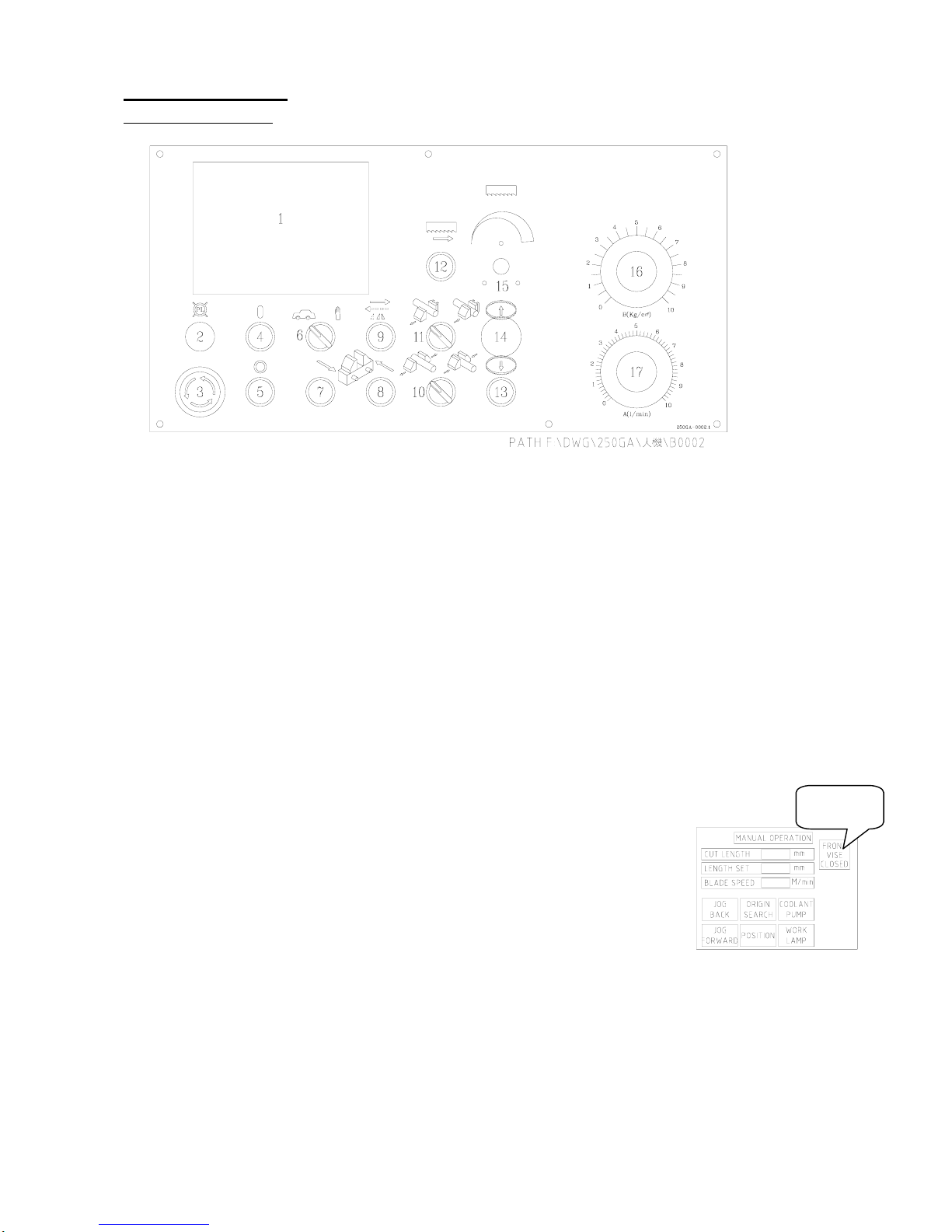
Mega H-400GA User manual

Automatic BANDSAW
H-400GA
INSTRUCTION MANUAL
MEGA MACHINE CO., LTD.
DOC NO:H-400GA-100.U
CTRL NO:06
UPDATE:2008/02/13
DOC VER:A1

FOREWORD
We hope that the owner of this automatic circular sawing machine will
have years of trouble-free service. The machine has been built
to the highest standards to enable fast accurate cutting to be obtained.
In order that the best results can be achieved from your MEGA circular sawing
Machine, we would ask all operators and maintenance engineers to READ
THIS MANUAL CAREFULLY BEFORE STARTING THE MACHINE.
The manual contains full instructions on installation, operation, lubrication,
maintenance and trouble-shooting.
As MEGA MACHINE COMPANY LIMITED is constantly improving the
design of its machines, there may be some instance where this book differs
somewhat from the machine with which you are concerned. So, always
quote the Serial Number of your machine, when ordering spare parts
or in correspondence relating to the machine.
MODEL :
Serial Number :
Request for service and spare parts should be made to :
ADDRESS: NO. 180, INDUSTRIAL ROAD, TAI-PING CITY, 41107 TAICHUNG,
TAIWAN R. O. C.
URL: www.bandsaw.com.tw
TEL: 886 4 22712877(PRES.) FAX:886 4 22715016

TABLE OF CONTENTS
1. Introductory Illustrations
1.1 Principal parts ------------------------------------------------------------------------ 1
2. Specifications
2.1 Specifications ------------------------------------------------------------------------- 2
2.2 Standard Accessories----------------------------------------------------------------. 2
3. Installation
3.1 moving and lifting -------------------------------------------------------------------- 3
3.2 Foundation layout and Set-up ------------------------------------------------------- 4
3.2.1 Foundation ----------------------------------------------------------------------- 4
3.2.2 Leveling ---------------------------------------------------------------------------5
3.2.3 Cleaning and oiling---------------------------------------------------------------.6
3.2.4 Power Source Connection ------------------------------------------------------ 6
4. Operation
4.1 Control Panel ------------------------------------------------------------------------- 7
4.2 LCD Panel illustration --------------------------------------------------------------- 9
Addition 1 - Amplifying Valve-----------------------------------------------------11
4.3 Operating preparation --------------------------------------------------------------- 13
4.4 Manual Operation --------------------------------------------------------------------15
4.5 Automatic operation -----------------------------------------------------------------16
4.6 Special Operation ---------------------------------------------------------------------17
4.7 Break -In Operation ------------------------------------------------------------------17
5. Maintenance
5.1 Oiling and Lubrication ---------------------------------------------------------------18
5.2 Others ----------------------------------------------------------------------------------19
6. Trouble Shooting Guide
6.1 Sawing Problems and Solution ------------------------------------------------------21
6.2 Minor Operating Troubles and Remedies ------------------------------------------22
6.3 Error Code ---------------------------------- ------------------------------------------23
7. Reference Charts
7.1 Standard cutting Chart -------------------------------------------------------------25
7.2 Standard cutting Chart -------------------------------------------------------------26
7.3 Standard cutting Chart -------------------------------------------------------------27
Appendix

1. INTRODUCTORY ILLUSTRATIONS (全行程)
1. 1Principal Parts
1

2 SPECIFICATIONS
2.1 SPECIFICATIONS
SPECIFICATIONS MODEL H400GA
(MM) Ø406
□
400W*400H
Cutting Capacity (IN) Ø16
□
16W*16H
Bundle Cutting (MM)
(IN)
320W*230H
13W*9H
(MM) 32*1.06*4570
Blade Size (IN) 1 1/4*0.042*180
(M/min) 25, 32, 42, 55, 70, 80 Variable Speed 20-80
Blade Speed (F/min) 82, 105, 138, 180, 230, 260 Variable Speed 65-260
(KW) Blade-3.75, HYD-0.75, Coolant-0.1
Motor Output (HP) Blade-5, HYD-1, Coolant- 1/8,
Auto Bar Feed (MM) 400
Multiple Feed Max (MM) 3600
Weight Net/Gross KG,lb 2450 / 2850 53900 / 6270
Specifications subject to change without notice for improvement and modification.
2.2 STANDARD ACCESSORIES
1. Tools with tool box .............………….……..….…....... 1 set
2. 7 ft.(2M) long roller table ...…………………..…......... 1 set
3. Band-cleaning wire brush ...………………….….......... 1 piece
4. Band saw blade .................…………………..……....... 1 piece
5. Instruction manual .............………………………........ 1 copy
2

3. INSTALLATION :
3.1 Moving and Lifting :
Unpack your machine carefully , and use a crane or forklift to set it in position.
If a crane is used to lift the machine attach the lifting cable carefully to the machine as shown in the
fig 2. If forklift is used then fig 3.
Sufficient space should be left around the machine to allow safe handling of materials , and inspection
and maintenance operation. Should there be other machinery causing vibration or dust that near your
machine, then precautions must be taken to keep your machine away from of vibration and dust.
(1) Use Crane :
Fig 2
(2) Use Forklift :
Fig 3
3

3.2 Foundation layout and set-up :
3.2.1 Foundation :
The foundation should be constructed of reinforced concrete and must be level and flat. After
the proper leveling position has been obtained , anchor the machine with anchor bolts.
The position of anchor bolts and floor dimensions are shown in fig 4:
Fig.4
□
Contact portion with floor
○
Position of anchor bolts
※
All leveling bolts should support the weight of the machine evenly .
4

3.2.2 Leveling :
The production accuracy of all precision machinery depends on the accuracy which the machine
is installed . Manufacturing tolerance of the machine can only be guaranteed if the machine is firmly
and properly installed . Once the machine is lowered on the prepared foundation . Machinist levels
should be used alternately on the vice slide plates and the work feed table , and adjust the left-and-right
and fore-and-aft level of the machine with leveling bolt .
The fore-and-aft level should be adjusted so that the level of the rear end is approximately 10 mm
(3/8" - 1/2") higher than the level of the front end , to provide proper return of the cutting fluid , and
easy operation of car feeding .
The left-and-right level should be adjusted so that the level of the left end is approximately 3 mm (1/8")
higher than the level of the right end , to provide proper return of the cutting fluid , After the proper
leveling position has been obtained anchor the machine with anchor bolts .
CAUTION : All leveling bolts should support the weight of the machine evenly .
Leveling as fig 5 below :
FIG 5
5

3.2.3 Cleaning and oiling :
After the machine has been placed in position , thoroughly remove its rust preventive coating using
a suitable cleaning solvent and then apply a coat of machine oil . To clean the machine , Kerosene is
preferable to gasoline . It does not evaporate and level dried slushy compound on finished surfaces.
Rags are better than waste as they leave no lint or strings. The machine as received by you. has been
completely drained of all oil. Before any attempt is made to run it .... Before any motor connections
are made .... every detail of the following oiling instruction must be complied with. Refer to the oiling
chart in chapter 7.
Especially , don't forget to fill up the cutting fluid mixture. Usually , the ratio of cutting fluid to
Water should be 1:30 - 1:50. Check the sight gauge to ascertain the fluid level in the tank every day.
Transmission gear box, bar feed gear box, hydraulic oil tank should to topped up monthly. Oil
levels should be strictly observed, for it is of primary importance for proper operation and long lift .
3.2.4 Power Source Connection:
A. Power Source - This machine is equipped with 5HP main motor and 1HP hydraulic motor ,
and 1/8HP coolant motor. Connect the power supply cable to the circuit breaker(N.F.B.)
terminals. The power supply to your machine should agree with the wring voltage that is
indicated on the label attached to the electrical enclosure and main motor.
B. Earth - Be sure to connect the earth cable to the earth terminal.
C. Starting - After making the necessary wiring connections, turn the power switch on the control
panel clockwise to turn power on, depress the vice limit switch (if necessary, e.g. if there is no
stock bar clamped in the vice) and push the button to see if the saw head moves upward. If the
saw head does not rise , the hydraulic pump motor is rotating in the wrong direction. If the motor
runs in the wrong direction, turn off the power switch and disconnect the power supply cable,
Then interchange any two phase connections.
6

4. OPERATION
4.1. Control Panel
1. LCD Panel illustration
2. PILOT LAMP -- This light will comes on when the power supply is on.
3. EMERGENCY STOP -- This switch is used for emergency case to stop the machine only.
Turn this switch clockwise makes power source on. When this switch is pressed, all machine's operation
stop immediately.
4. POWER SWITCH ON -- This switch is used for turning on the power by depressing it.
5. POWER SWITCH OFF -- This switch is used for turning off the power by depressing it.
6. AUTO - MANUALSELECTOR -- For continuous cutting , turn this selector to left "AUTO".
To individually operate each function, turn this switch to right "manual".
7. MANUAL FEED FORWARD --When this button is pressed the workpiece moves forward.
The workpiece stops advancing when the button is released.
NOTE: Turn (10) VISE SWITCH right position before depress switch (12) BLADE DRIVE to cutting.
8. MANUAL FEED BACKWARD --When this button is pressed the workpiece moves backward.
The workpiece stops moving when the button is released.
NOTE: Don't depress (7) and (8) two switches, if the workpiece are clamped by
both front and rear vises in the meantime.
9. FRONT INCHING OPEN SWITCH -- The front vise clamp the
workpiece when turn switch NO.(11) right and press button NO.(9)
1.5sec in the same time. Then the front vise hold the workpiece
after the LCD “Front vise closed” light.
10. REAR VISE SWITCH -- This switch control the rear vise jaws in manual
mode, switched to the left makes the front vise open. and switched to the right
makes the front vise clamp.
11. FRONT VISE SWITCH -- The switch control the front vise jaws in manual mode, The front
vise clamp when turn the switch to right. Then if release the switch, the switch come back to
the middle position, the vise doesn’t hold the workpiece. If operator would like to hold the
workpiece, he would follow the (9) illustration.
The front vise open little by little if the guide arm is under the front vise when the switch turn to left.
And the front vise open continuously if the guide arm is above the front vise. At last, if release the
switch, the switch come back to the middle position.
7
Light

12. BLADE DRIVE BUTTON -- When this button is pressed, both the saw blade motor and the cutting
fluid pump operate and saw head begins to descend. The saw head descends quickly until the feeler of
the quick approach device comes into contact with the workpiece and thereafter, it will descend at the
designated cutting speed.
13. QUICK APPROACH BUTTON -- While this button is pressed, the saw head descends quickly.
This button is used to cause the saw blade to approach the work quickly when the saw blade is at a
distance from the workpiece. When the feeler of the quick approach device comes into contact with
the work, the saw head stops descending at that position even this button is still pressed.
14. SAW FRAME RAISE BUTTON -- When this button is pressed, the saw blade motor stops and the
saw head ascends. The saw head stops ascending at that position when the button is released.
15. INVERTER CONTROL KNOB -- Please turn left for being slow speed wanted, turn right for being
fast speed wanted. Please refer to (JPS) pd-Series IGBT Inverter Instruction Manual or Please refer to
(FUJI) FRENIC 5000G9S/P9S Instruction Manual.
16. CUTTING PRESSURE CONTROL KNOB -- When this control dial is turned clockwise the
cutting pressure increases, when it is turned count clockwise, the cutting pressure decreases.
17. FEED RATE CONTROL KNOB -- When this control dial is turned clockwise the feed rate of
the cutting increases, when it is turned counter clockwise, the feed rate decreases.
8

4.2 LCD Panel illustration
4.2.1 LCD Panel operation sequence
After powered on, the LCD panel
will display as fig. right. By
touching screen, the LCD panel
will escape to the next figure.
Manual mode:
To individually operate each
function, turn the “AUTO - MANUAL
SELECTOR”to right “manual”.
Operator not only can control
coolant pump and work lamp
on/off but also the feed rate.
1. LENGTH SET:
When press the LENGTH SET
button,it will display the figure
“Numeric Keypad”.Operator can
setting the length on this pad.
2. POSIT:
When press the POSIT button,it
will display the value of the
length set column.
Auto mode:
For continuous cutting , turn
“AUTO - MANUALSELECTOR”to left
"AUTO".
1. QUANTITY SETTING:
When press the SETTING
button,it will display the figure
“FULLY AUTO”.Operator can
setting the length and quantity
here.
2. ZERO SETTING:
WhenpresstheZERO
button,it will change the value of
quantity to zero.
9
LENGTH SET
BUTTON
POSIT BUTTON
(AUTO OPERATION)(FULLY AUTO)
QUANTITY SETTING ZERO SETTING
(Numeric Keypad)(MANUAL OPERATION)

PARAMETER SETTING:
( The panel function key F5)
It can adjust the feed system delay
time and the frame system delay
time and the vise jaw open time
and the others by password, which
set by manufacturer or agent.
Operator not only can change unit
between mm and inch,but also can
change English operating type to
Chinese operating type if really
necessary.
INPUT MONITOR:
The panel function key F1
10
(PARAMETER SETTING)(FEED SYSTEM DELAY TIME)
(FRAME SYSTEM DELAY (VISE JAW OPEN TIME)
(COMPENSATION)
(BLADE PARAMETER) (PROGRAM VER)

Amplifying Valve
(1.) The outlines and hydraulic circuits:
(2.) SET-UP
A. The hydraulic pressure indicated in line <p> should be kept in constant during the whole stroke
of the lifting cylinder, i.e. Between the very top and bottom position of the swinging saw frame.
we use springs <r> inside of lifting cylinder to balance/compensate the pressure changes (pressure
varies due to saw frame swinging up and down ) in line <p>. above procedures have been done in
our factory before machine dispatched , now for checking test, please dry run the machine by raising
the saw frame to the very top position and push the saw blade drive button, and having the quick
approach rod lifted (limit switch un-touched), then check the hydraulic pressure in line <p> by
reading the pressure gauge at line <p> to see if the pressure readings keep the same during the whole
stroke.
(maximum 1 kg/sq.cm varies allowed) the pressure reading should be as follows:
8 KG/SQ.CM ............250/300 MODELS
10 KG/SQ.CM ............360/400/450 MODELS
11

B. Re-zeroing knob "a" & "b" on the amplifying valve:
For zeroing knob "a", there is a hydraulic pressure gauge as drawing <S> needed, Please plug it
onto the outlet on the amplifying valve.
Pressure read at line <p> as the primary pressure............pressure <p>
Pressure read at amplifying valve as the secondary pressure.. pressure <s>
The primary pressure should be kept the same reading, and the secondary pressure can be adjusted
by turning knob "b" for cutting pressure settings zeroing knob "a" :
------------------
Dry run the machine as stated in above paragraph,
Turn knob "b" while reading pressure <s>, If there is any pressure can be read, then turn knob "a"
While watching saw frame, if the saw frame shall stand still there without coming down, then there is
the zero position of the knob "a" ( zero feed-rate ), check the " △" mark on the knob "a" to see if
this mark pointing to "0" position. If not, loosen set screw and zeroing it ( Please make sure tighten
the set screw after zeroing ). zeroing knob "b" :
------------------
After zeroing knob "a", turn knob "a" at "5" position, and let the machine running in the same
condition as previous did - dry running. turn knob "b" while reading pressure <s>, If the pressure
reach 5.5 to 6 kg /sq.cm, then loosen the set screw on the knob "b" and have the " △" mark
pointing to "5" position and tighten the set screw.
(3.) OPERATION
Knob "a" is for maximum feed-rate setting:
The smaller the diameter of the material being cut, the higher feed-rate.
The softer the material being cut, the higher feed-rate can be set. And vise-versa.
Knob "b" is for cutting pressure setting:
The tougher the material being cut, the higher cutting pressure needed. For instance, when cutting
thin pipes/tubes, mild carbon steels, Only little pressure needed, and for stainless/high alloy tool
steels or inconel special steels, high cutting pressure should be needed. There are bothAISI/JIS
material codes shown on the control panel, Please refer to it for proper cutting pressure setting.
LIMITATION: The sum of the number set on knob "a" and "b" can not exceed 10.
12

4.3 OPERATING PREPARATION
There are several steps will be taken before start the machine.
(1) CHOOSE PROPER SAW BLADE :
Select the saw blade best suited to the workpiece to be cut, Size and shape of the workpiece , and
type of material should all be considered when selecting the saw blade to be used . There is a reference
chart in chapter 9 which can help you to select the right saw blade and cutting conditions .
(2) UNPACK THE SAW BLADE :
Usually the saw blade is packed in 3 circle ,unpack it one circle first grip the part to release another 2
circles gradually , tear off the saw-cap protective shield , inspect the blade teeth , make sure that the
cutting edge of the blade teeth point to the right . If they point to the left the blade should be turned over.
(3) PLACE THE SAW BLADE ONTO BOTH THE DRIVEAND DRIVEN WHEELS ----
a. Turn the hydraulic blade tension handle clockwise , to fully loosen the driven wheel .
b. Open both the drive and driven wheel covers , place the saw blade onto both the drive and driven
wheels. Check the cutting edge of the saw blade , to ensure that it point to the right.
c. Insert the saw blade into both the left and right blade guides so that the back edge of the saw blade
touches the back-up roller of each guide .
d. The back edge of the saw blade should make contact with the flange of the drive and driven wheel ,
turn count -clockwise the hydraulic blade tension handle to tighten the saw blade , Then the blade
is properly tensioned .
e. Don't forget to tighten the insert adjusting screw .
(4) WORKPIECE CLAMPING :
a. Raise the saw frame , open the vise , place the workpiece on the roller table .
b. Gently push the workpiece into the roller-feed vise, taking care not hit the feed rollers.
c. Clamp the workpiece in vise.
(5) ADJUST THE BLADE GUIDE ARM :
Blade guide arm adjustment
a. unlock the guide arm and carbide guides to move the guide arm.
1. Turn clockwise throat flow control valve V1 to close the in-flow to the guide arm lock and
carbide tightening.
2. Turn counter-clockwise throat flow control valve V2 to let the oil out back to tank, to release
the guide arm lock and carbide tightening.
3. Move the guide arm to the proper position that just wide enough to clear the workpiece for cutting.
b. lock the guide arm and carbide guides before cutting.
1. Turn counter-clockwise throat flow control valve V1 to let the in-flow to the guide arm lock and
carbide tightening.
2. Turn clockwise throat flow control valve V2 to close the oil out back to tank, to have the guide
arm locked and carbide tightened to the saw blade. Properly position the blade guide arms according
to the diameter (or the width) of the workpiece to be cut.
(6) ADJUST THE POSITION OF THE WIRE BRUSH :
a. loosen the lock lever of the wire brush case.
b. Manually move the wire brush case so that wire brush just contacts the cutting edge of the saw blade.
c. Tighten the lock lever.
13

(7) ADJUST THE FEED RATE :
Select suitable feed rate for the workpiece to be cut. This varies according to the size and shape of the
workpiece, type of material , and what type of saw blade is being used. As a guide hard materials, wide
workpiece or structural sections and tubing have to be cut at a slower rate that mild steel bar.
As concerns the saw blade , high speed steel is better than carbon steel, and bi-metal alloy is better than
high speed steel. Roughly the ratio of feed speeds could be 1:2:3
(8) CUTTING LENGTH PRESET :
As in LCD panel “Numeric Keypad”, operator can set multiple cutting. There are 1~999999 mm
cutting length set and 1~999999 cutting quantity set on each program, showed in the LCD panel
“MANUAL OPERATION” and “AUTO OPERATION”.
(9) SELECT THE SAW BLADE SPEED :
There are 6 speeds provided : 25, 32, 42, 55, 70, 80 M/min
If a optional variable speed drive is equipped the speed to be 20 to 80 M/Min steplessly.
14

4.4 MANUALOPERATION :
Place the workpiece to be cut on
the work table , decide how long you
want the off-cut , and carry out all the
procedures as described above in [4.3]
Operating Preparation.
(1) Press the SAW FRAME RAISE
BUTTON to lift the saw frame until
the cutting edge of the saw blade
clears the workpiece by 1/2 to 3/4
inch.
(2) Turn the AUTO-MANUAL
SELECTOR to manual.
(3) Clamp the workpiece.
`
(4) Adjust the spacing of the blade
guide arms.
(5) Preset the required cutting length
of the workpiece.
(Please refer to the [4.2] LCD Panel
illustration )
(6) Press the MANUAL FEED FORWAR
D
button until the workpiece reach to
the position
of the cutting edge.
(The first workpiece must be measur
e
by hand with ruler)
(Measure by hand with ruler)
(7) Adjust the FEED RATE.
(The feed rate must be set
according to the material)
(8) Press the BLADE DRIVE BUTTON to
start both the saw blade motor and
the cutting fluid pump and the saw
frame begins to descend.
(9) After completion of the cut saw
blade stops at the lower limit
position.
(10) Depress the RAISE button to cut
next piece again.
◎Before you start to cut the workpiece, you must inspect that....
☆The workpiece is well clamped.
☆The saw blade and the feed rate are suitable for the material being cut.
☆The speed of the saw blade is suitable for the material being cut.
☆The insert adjusting screw of the saw and the blade guide arm are all tightened.
☆Sufficient tension is placed on the saw blade.
☆The wire brush is in properly positioned.
☆ There is sufficient cutting fluid in good condition.
☆The off-cut length is as required. 15
Blade drive button
Adjust the spacing of
the blade guide arm
Feed Feed backward
SAW FRAME
RAISE BUTTON
AUTO-MANUAL
SELECTOR
Cutting pressure
control knob
Feed rate control
knob

4.5 AUTO OPERATION :
16
Having finished all the procedures
described above in [4.3] Operating
Preparation.Then Place the
workpiece to be cut on the work tabl
e
and clamp it.
(A) Turn the “AUTO-MANUAL
SELECTOR” to “auto”.
(B)Press the “QUICK APPROACH
BUTTON”to make the saw
frame descend quickly to touch
the lower limit position,it will
then rise automatically to the
height preset.
(C)Make any necessary adjustments
to HEIGHT SELECTOR to ensure
that the saw blade clearly higher
than material by 1/2 to 3/4 inch
then repeat (B) to check setting.
(D)Press “MANUAL FEED FORWARD
“ button until the workpiece
reach to the position of the
cutting edge.
(E) Preset the number of cuts
required.
(F) Press the “BLADE DRIVE
BUTTON” to start both the saw
blade motor and the cutting
fluid pump.
The saw frame begins to
descend to cut workpiece.
(G) After the required number of
cut has been completed, the saw
frame will lift to the raised
position and all machine
operation will stop.
(H) The machine will automaticlly
stop, when the workpiece is so
short that it can no longer be
automatically feed.
AUTO-MANUAL
SELECTOR
MANUAL FEED
FORWARD BUTTON
BLADE DRIVE
BUTTON

4.6 SPECIALOPERATION :
(1) While you are cutting a workpiece, if the saw blade suddenly jams in the workpiece, depress the
FRAME RAISE button to lift the saw frame immediately.
(2) The saw blade jamming in the workpiece is most likely because of :
a. Slippage occurring between saw blade and drive wheel. Tension placed on the saw blade is not
sufficient.
b. Slippage occurring between drive belt and motor pulley. Tension on drive belt is not sufficient or
belt is worn.
c. Broken teeth on saw blade.
d. Too blunt saw blade.
e. Too fine tooth spacing on saw blade for material being cut.
f. Too fast feed rate for material being cut and blade used.
4.7 BREAK-IN OPERATION:
When a new blade is used , be sure to first break in the blade before using it for extended operation.
Failure to break in the blade will shorten the service lift of the blade ,and result in less than optimum
efficiency. To break in the blade ,proceed as follow :
(1) Reduce the blade speed setting to one half of its normal setting .
(2) Lengthen the time required for cutting to 2-3 times that of normal.
(3) The break-in operation can be considered sufficient if all unusual noises or metallic sounds have
been eliminated. (For instance, to completely break in the blade, a minimum of five complete cuts
of a 200mm (8 ins) diameter work- piece will be required.)
(4) After the break-in operation has been completed, return the blade speed and feed rate to their
normal setting.
17
Table of contents
Other Mega Saw manuals