MegaLife ML-RS-CQ8.0Pd/NaC-K User manual
Air-to-water Heat Pump Monobloc 7\SH
Owner's Manual
Original Instructions
Air Conditioners
www.megalife.ma


To Users
Thank you for selecting RXU product. Please read this instruction manual carefully before installing and using
the product, so as to master and correctly use the product. In order to guide you to correctly install and use our
product and achieve expected operating effect, we hereby instruct as below:
(1) This equipment should be installed, operated or maintained by the qualified servicemen who have had
VSHFL¿FWUDLQLQJ'XULQJRSHUDWLRQDOOVDIHW\LVVXHVFRYHUHGLQWKHODEHOV8VHU¶V0DQXDODQGRWKHUOLWHUDWXUH
should be followed strictly. This equipment is not intended for use by persons (including children) with
reduced physical, sensory or mental capabilities, or lack of experience and knowledge, unless they have
been given supervision or instruction concerning use of the appliance by a person responsibility for their
safety. Children should be supervised to ensure that they do not play with the appliance.
(2) This product has gone through strict inspection and operational test before leaving the factory. In order to
avoid damage due to improper disassembly and inspection, which may impact the normal operation of unit,
please do not disassemble the unit by yourself. You can contact with the special maintenance center of our
company if necessary.
(3) For personal injury or property loss and damage caused by improper operation such as improper
installation and debugging, unnecessary maintenance, violation of related national laws and rules and
industrial standard, and violation of this instruction manual, etc., we will bear no liability.
(4) When the product is faulted and cannot be operated, please contact with our maintenance center as soon
as possible by providing the following information.
ЬContents of nameplate of product (model, cooling/heating capacity, product No., ex-factory date).
ЬMalfunction status (specify the situations before and after the error occurs).
(5) All the illustrations and information in the instruction manual are only for reference. In order to make the
product better, we will continuously conduct improvement and innovation. We have the right to make
necessary revision to the product from time to time due to the reason of sales or production, and reserve
the right to revise the contents without further notice.
(6) 7KH¿QDOULJKWWRLQWHUSUHWIRUWKLVLQVWUXFWLRQPDQXDOEHORQJVWR0HJD/LIH

Contents
Safety Notices (Please be sure to abide ) ...................................................................1
1. Diagram of the Operating Principle .........................................................................7
2. Operating Principle of the Unit.................................................................................8
3. Nomenclature...........................................................................................................10
4. Installation Example ............................................................................................. 11
5. Main Components ..................................................................................................13
6. Installation Guideline of the Unit ...........................................................................15
6.1 Instruction to installation .................................................................................................15
,QVWDOODWLRQRIWKH0RQREORF8QLW.....................................................................................15
6.3 Water Volume and Pump Capacity (with pump) .............................................................17
6.4 Water Volume and Expansion Vessel Pressure..............................................................18
6.5 Selection of Expansion Vessels ......................................................................................18
7. Remote Air Temperature Sensor............................................................................ 19
8. Thermostat...............................................................................................................20
9. 2-Way Valve..............................................................................................................20
10. 3-Way Valve............................................................................................................21
11. Wired Controller ...................................................................................................22
12. Other Auxiliary Heat Sources ..............................................................................22
13. Gate-controller .....................................................................................................22
14. Charging and Discharging of Refrigerant...........................................................23
15. Installation of Insulated Water Tank ...................................................................24
15.1 Installation measure......................................................................................................24
15.2 Outline dimension and parameter of water tank ...........................................................25
15.3 Connection of waterway system ...................................................................................26
15.4 Electric wiring work ......................................................................................................27
16. Wring Diagram.......................................................................................................28
16.1 Control Board................................................................................................................28
16.2 Electric Wiring ...............................................................................................................35
17. Commissioning......................................................................................................37
17.1 Check before startup.....................................................................................................37
17.2 Test run .........................................................................................................................38
18. Daily Operation and Maintenance .......................................................................39

Air-to-water Heat Pump Monobloc 7\SH
1
Safety Notices (Please be sure to abide )
WARNING: If not abide strictly, it may cause severe damage to the unit or the
people.
NOTE: If not abide strictly, it may cause slight or medium damage to the unit or the
people.
This sign indicates that the operation must be prohibited. Improper operation may
cause severe damage or death to people
This sign indicates that the items must be observed. Improper operation may
cause damage to people or property.
NOTE
After receipt of the unit, check it for appearance, unit model compared with your desire
and attachments.
'HVLJQDQGLQVWDOODWLRQZRUNRIWKHXQLWPXVWEHSHUIRUPHGE\DXWKRUL]HGSHUVRQQHO
according to applicable laws and regulations and this Instruction.
$IWHULQVWDOODWLRQZRUNWKHXQLWFDQQRWEHHQHUJL]HGXQOHVVWKHUHLVQRWDQ\SUREOHPLQ
check.
Ensure periodical clean and maintenance of the unit after normal operation of the unit
for longer life and reliable operation.
If the supply cord is damaged, it must be replaced by the manufacturer, its service
DJHQWRUVLPLODUO\TXDOL¿HGSHUVRQVLQRUGHUWRDYRLGDKD]DUG
The appliance shall be installed in accordance with national wiring regulations.
This product is a kind of comfort air conditioning, and is not allowed to be installed
ZKHUHWKHUHDUHFRUURVLYHH[SORVLYHDQGLQÀDPPDEOHVXEVWDQFHVRUVPRJRWKHUZLVH
LWZRXOGOHDGWRRSHUDWLRQIDLOXUHVKRUWHQHGVHUYLFHOLIHILYHKD]DUGRUHYHQVHYHUH
injuries. Special air conditions are required for where mentioned above.
Correct Disposure
This marking indicates that this product should not be
GLVSRVHGZLWKRWKHUKRXVHKROGZDVWHVWKURXJKRXWWKH(87R
prevent possible harm to the environment or human health from
uncontrolled waste disposal,recycle it responsibly to promote the
sustainable reuse of material resources. To retuern your used
device,please use the return and collection systems or contact
the retailer where the product was purchased. They can take this
product for environmental safe recycling.
R410A(R32/125:50/50):2087.5
Air-to-water Heat Pump Monobloc 7\SH
2
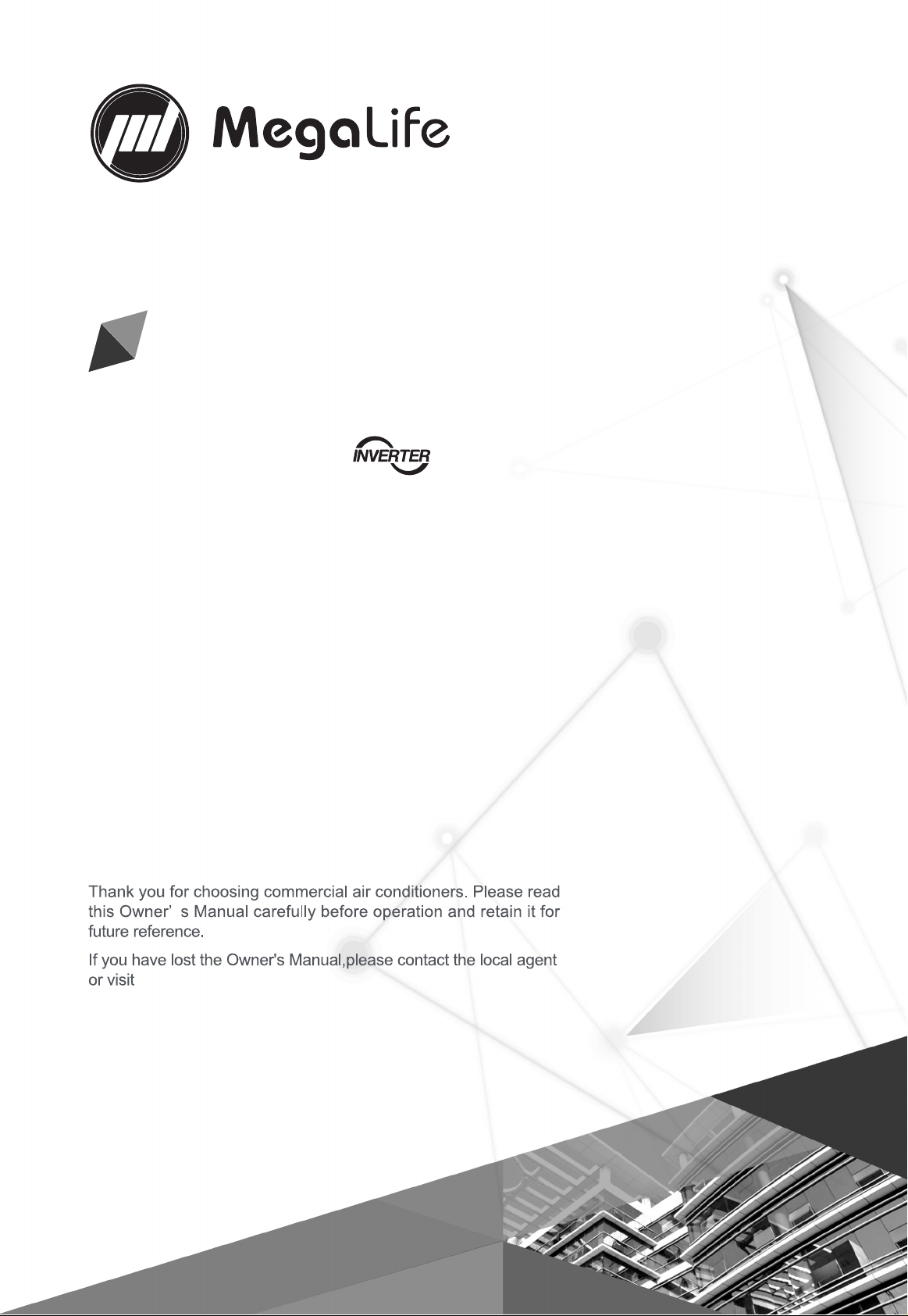
WARNING
Once abnormality
likeburning smell occurs,
please cut off the power
supply immediately and
then contact with service
center.
If the abnormality still exists,
the unit may be damaged
DQGHOHFWULFVKRFNRU¿UH
may result.
'RQWRSHUDWHWKHXQLWZLWK
wet hand.
Otherwise, it may cause
electric shock.
Before
installation,please see
if the voltage of local
place accords with
that on nameplate
of unit and capacity
of power supply,
power cord or socket
is suitable for input
power of this unit.
Special circuit must be
adopted for power supply
WRSUHYHQW¿UH
'RQRWXVHRFWRSXV
multipurpose plug or mobile
terminal board for wire
connection.
Be sure to pull out the
power plug and drain the
indoor unit and water tank
when unit is not in use for a
long time.
Otherwise, the accumulated
dust may cause
RYHUKHDWLQJ¿UHRUIUHH]HRI
water tank or coaxial heater
exchanger in winter.
Never damage the
electric wire or use
the one which is not
VSHFL¿HG
Otherwise, it may
cause overheating or
¿UH
Air-to-water Heat Pump Monobloc 7\SH
3
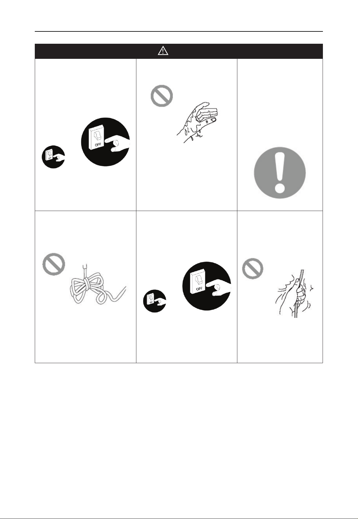
Before cleaning please cut
off the power supply.
Otherwise, it may cause
electric shock or damage.
The power supply must
adopt special circuit with
leakage switch and enough
capacity.
8VHUFDQQRWFKDQJH
power cord socket
without prior consent.
Wiring working
must be done by
professionals. Ensure
good earthing and
GRQWFKDQJHHDUWKLQJ
mode of unit.
Earthing: the unit must
be earthed reliably ! The
earthing wire should
connect with special device
of buildings.
If not, please ask the
TXDOL¿HGSHUVRQQHOWR
install.
)XUWKHUPRUHGRQWFRQQHFW
earth wire to gas pipe,
water pipe, drainage pipe or
any other improper places
which professional does not
UHFRJQL]H
Never insert any foreign
matter into outdoor unit to
avoid damage . And never
insert your hands into the
air outlet of outdoor unit.
'RQWDWWHPSWWRUHSDLU
the unit by yourself.
Improper repair may
cause electric shock
RU¿UHVR\RXVKRXOG
contact the service
center to repair.
4
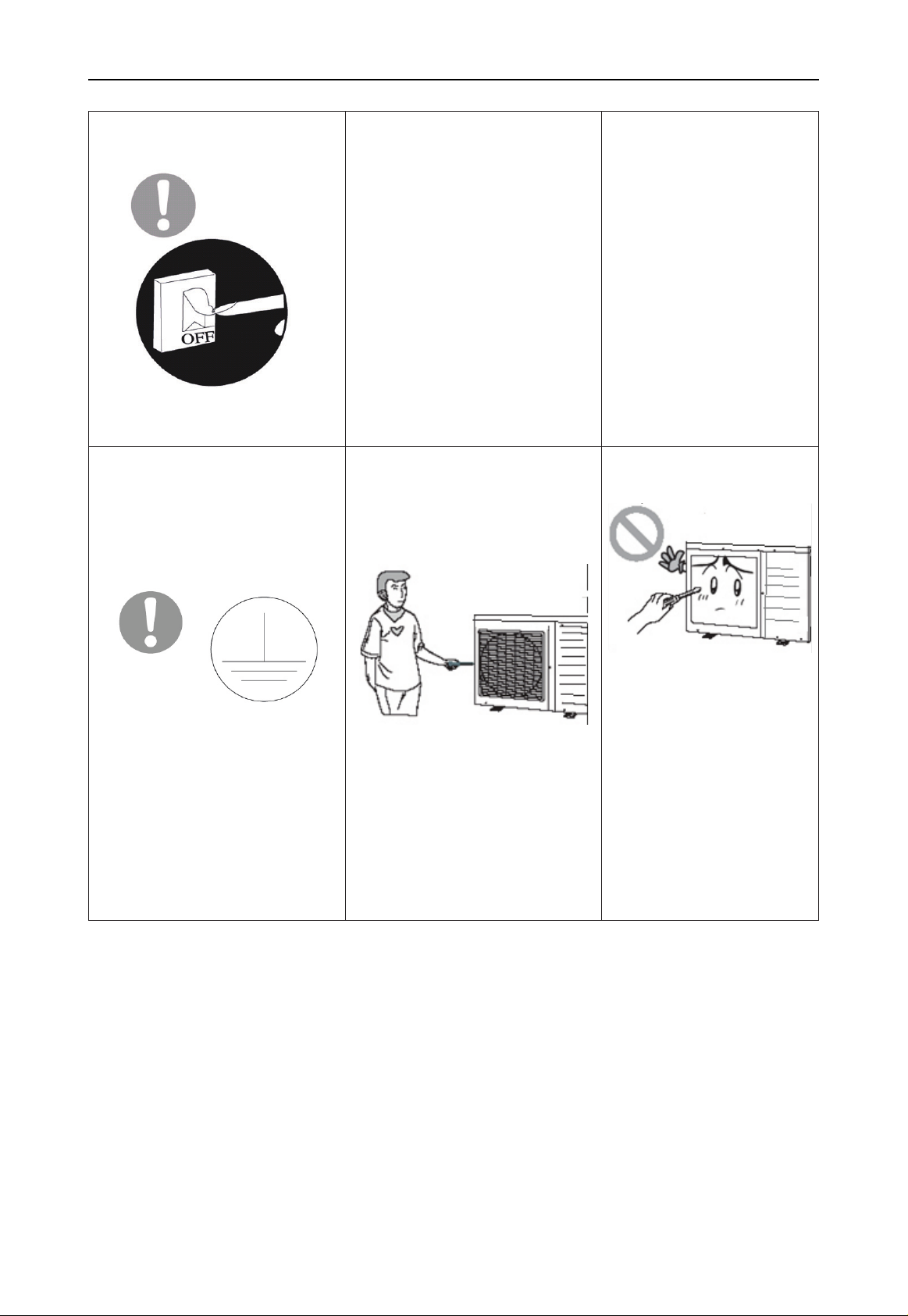
'RQWVWHSRQWKHWRSRIWKH
unit or place anything on it.
There is the danger of fall of
things or people.
Never block the air inlet and
outlet of unit.
,WPD\UHGXFHHI¿FLHQF\RU
cause stop of the unit and
HYHQ¿UH
.HHSSUHVVXUL]HG
spray, gas holder and
so on away from the
unit above 1m .
,WPD\FDXVH¿UHRU
explosion.
Please note whether the
LQVWDOODWLRQVWDQGLV¿UP
enough or not.
If damaged, it may cause
fall of the unit and injury of
people.
8QLWVKRXOGEHLQVWDOOHG
at the place with good
ventilation to save energy.
When there is not
water in water tank,
never power the unit
on to run.
Air-to-water Heat Pump Monobloc 7\SH

5
NOTE
Before installation, please check if the adopted power is accordance with that listed
on nameplate, and check the safety of power.
The unit shall contact with the supply mains by a full disconnection device under
overvoltage category Ⅲ.
Before using, please check and confirm if wires and water pipes are connected
FRUUHFWO\WRDYRLGZDWHUOHDNDJHHOHFWULFVKRFNRU¿UHHWF
'RQ¶WRSHUDWHWKHXQLWZLWKZHWKDQGDQGGRQ¶WDOORZFKLOGUHQWRRSHUDWHWKHXQLW
7KH2QRIILQWKHLQVWUXFWLRQLVIRUWKHRSHUDWLRQWRRQDQGRIIEXWWRQRI3&%IRUXVHUV
cut off power means to stop supplying power to the unit.
'RQ¶WGLUHFWO\H[SRVHWKHXQLWXQGHUWKHFRUURVLYHDPELHQWZLWKZDWHURUGDPSQHVV
'RQ¶WRSHUDWHWKHXQLWZLWKRXWZDWHULQZDWHUWDQN7KHDLURXWOHWLQOHWRIXQLWFDQQRWEH
blocked by other objects.
The water in unit and pipeline should be discharged if the unit is not in use, to prevent
the water tank, pipe line and water pump from frost-cracking.
Never press the button with sharp objects to protect manual controller. Never use
other wires instead of special communication line of the unit to protect control elements.
1HYHUFOHDQWKHPDQXDOFRQWUROOHUZLWKEHQ]HQHWKLQQHURUFKHPLFDOFORWKWRDYRLG
fading of surface and failure of elements. Clean the unit with the cloth soaked in neutral
eradicator. Slightly clean the display screen and connecting parts to avoid fading.
The power cord must be separated with the communication line.
Air-to-water Heat Pump Monobloc 7\SH
6
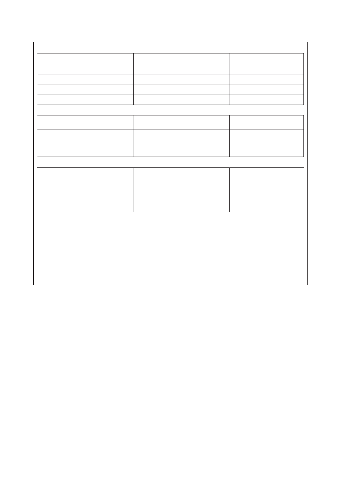
maximum and minimum water operating temperatures.
Item Minimum water operating
temperatures
Maximum
water operating
temperatures
Cooling 7°C 25°C
Heating 25°C 55°C
Water heating 40°C 80°C
maximum and minimum water operating pressures.
Item Minimum water operating
pressures
Maximum water
operating pressures
Cooling
0.05MPa 0.25MPaHeating
Water heating
maximum and minimum entering water pressures.
Item Minimum entering water
pressures
Maximum entering
water pressures
Cooling
0.05MPa 0.25MPaHeating
Water heating
The range of external static pressures at which the appliance was tested (add-on
KHDWSXPSVDQGDSSOLDQFHVZLWKVXSSOHPHQWDU\KHDWHUVRQO\,IWKHVXSSO\FRUG
is damaged, it must be replaced by the manufacturer, its service agent or similarly
TXDOL¿HGSHUVRQVLQRUGHUWRDYRLGDKD]DUG
The appliance is intended to be permanently connected to the water mains and not
connected by a hose-set.
,IWKHUHLVDQ\TXHVWLRQSOHDVHFRQWDFWZLWKORFDOGHDOHUDXWKRUL]HGVHUYLFHFHQWHU
agencies or our company directly.

7
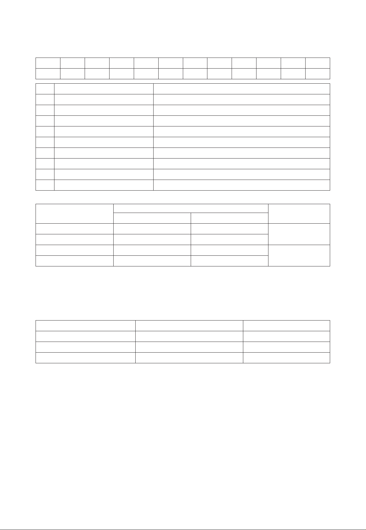
1. Diagram of the Operating Principle
No. Name No. Name No. Name No. Name
1 Inverter compressor 13 Solenoid valve 25 :DWHU¿OWHU 37 Solar system inlet
temperature sensor
2'LVFKDUJH
temperature sensor 14 EXV 2 26
Inlet temperature
sensor (plate heat
exchanger)
38 Water separator
3 High-pressure switch 15 Low pressure sensor 27 Safety valve 39 2-way Valve 1
4 High pressure sensor 16 Suction temperature
sensor 28 Exhaust valve 40 Floor radiator
5 4-way Valve 17
Outlet water
temperature sensor
(plate heat exchanger)
29 3-way valve 2 41 Water collector
6Finned heat
exchanger 18 Auxiliary electric
heater 30
Water tank
temperature
sensor 1
42 )&8
7Environment
temperature sensor 19 Expansion tank 31 Water tank 43 By-pass valve
8'HIURVWLQJ
temperature sensor 20 Main outlet
temperature sensor 32
Solar system
outlet temperature
sensor
44 Vapor liquid
separator
9 Filter 21 Main water pump 33 6RODUV\VWHPÀRZ
switch 45 Main plate heat
exchanger
10 EXV 1 22 0DLQÀRZVZLWFK 34 Solar system water
pump 46
Water tank
temperature sensor
2
11 Flasher 23 Outlet pipe connector 35 Solar panel
12 Pressure sensor 24 Inlet pipe connector 36
Solar panel
temperature
sensor

8
2. Operating Principle of the Unit
'&,QYHUWHU$LUWR:DWHU+HDW3XPSLVFRPSRVHGRIWKHXQLW)&8DQGZDWHUWDQN2SHUDWLRQIXQFWLRQV
(1) &RROLQJ
Cooling:LQFRROLQJPRGHWKHUHIULJHUDQWLVFRQGHQVHGLQWKHDOXPLQXP¿QFRSSHUWXEHDQGHYDSRUDWHGLQWKH
plate heat exchanger. Via the heat exchange with water in the plate heat exchanger, the temperature of water
decrease and it releases heat while the refrigerant absorbs heat and evaporates. With the help of wired controller,
WKHRXWÀRZWHPSHUDWXUHFDQPHHWWKHXVHU¶VUHTXLUHPHQW7KURXJKWKHFRQWURORIYDOYHWKHORZWHPSHUDWXUHZDWHU
in the system is connected with indoor fan coil and underground pipe, and exchanges heat with the indoor air so
that the indoor temperature decreases to the required range.
(2) +HDWLQJ
Heating:LQKHDWLQJPRGHWKHUHIULJHUDQWHYDSRUDWHVLQWKHDOXPLQXP¿QFRSSHUWXEHDQGLVFRQGHQVHGLQWKH
plate heat exchanger. Via the heat exchange with water in the plate heat exchanger, the water absorbs heat and
its temperature increase while the refrigerant releases heat and is condensed. With the help of wired controller, the
RXWÀRZWHPSHUDWXUHFDQPHHWWKHXVHU¶VUHTXLUHPHQW7KURXJKWKHFRQWURORIYDOYHWKHKLJKWHPSHUDWXUHZDWHULQ
the system is connected with indoor fan coil and underground pipe, and exchanges heat with the indoor air so that
the indoor temperature increases to the required range.
(3) :DWHUKHDWLQJ
Water heating: in water heating mode: the refrigerant evaporates in the aluminum fin-copper tube and is
condensed in the plate heat exchanger. Via the heat exchange with water in the plate heat exchanger, the water
absorbs heat and its temperature increase while the refrigerant releases heat and is condensed. With the help of
ZLUHGFRQWUROOHUWKHRXWÀRZWHPSHUDWXUHFDQPHHWWKHXVHU¶VUHTXLUHPHQW7KURXJKWKHFRQWURORIYDOYHWKHKLJK
temperature water in the system is connected with the coil pipe of bearing water tank, and exchanges heat with the
water in the water tank so that the temperature of water tank increases to the required range.
(4) &RROLQJZDWHUKHDWLQJ
Cooling + water heating: when cooling mode exists together with the water heating mode, the user can set the
priority of these two modes based on the needs. The default priority is heat pump. That is under the default setting,
if cooling mode exists together with the water heating mode, the heat pump gives priority to cooling. In that case,
ZDWHUKHDWLQJFDQRQO\UHDOL]HGZLWKHKHDWHURIWKHZDWHUWDQN,QYHUVHO\WKHKHDWSXPSJLYHVSULRULW\WRZDWHU
KHDWLQJDQGVZLWFKHVWRFRROLQJDIWHU¿QLVKLQJZDWHUKHDWLQJ
(5) +HDWLQJZDWHUKHDWLQJ
Heating+ water heating: when heating mode exists together with the water heating mode, the user can set the
priority of these two modes based on the needs. The default priority is heat pump. That is under the default setting,
if heating mode exists together with the water heating mode, the heat pump gives priority to heating. In that case,
ZDWHUKHDWLQJFDQRQO\UHDOL]HGZLWKHKHDWHURIWKHZDWHUWDQN,QYHUVHO\WKHKHDWSXPSJLYHVSULRULW\WRZDWHU
KHDWLQJDQGVZLWFKHVWRKHDWLQJDIWHU¿QLVKLQJZDWHUKHDWLQJ
(6) (PHUJHQF\PRGH
Emergency mode: this mode is only available for heating and water heating. When the monobloc unit stops
GXHWRPDOIXQFWLRQHQWHUWKHFRUUHVSRQGLQJHPHUJHQF\PRGHDVWRKHDWLQJPRGHDIWHUHQWHULQJWKHHPHUJHQF\
PRGHKHDWLQJFDQRQO\EHUHDOL]HGWKURXJKHKHDWHU:KHQWKHVHWWLQJRXWÀRZWHPSHUDWXUHRULQGRRUWHPSHUDWXUH
LVUHDFKHGWKHHKHDWHUZLOOVWRSUXQQLQJDVWRZDWHUKHDWLQJPRGHWKHHKHDWHUVWRSVZKLOHWKHHKHDWHURIZDWHU
tank runs. When the setting temperature or water tank is reached, the e-heater will stop running.
(7) 4XLFNZDWHUKHDWLQJ
Quick water heating: in quick water heating mode, the unit runs according to the water heating control of heat
pump and the e-heater of water tank runs at the same time.

9
(8) +ROLGD\PRGH
Holiday mode:this mode is only available for heating mode. This mode is set to keep indoor temperature or
OHDYLQJZDWHUWHPSHUDWXUHLQDFHUWDLQUDQJHVRDVWRSUHYHQWZDWHUV\VWHPRIWKHXQLWIURPIUHH]LQJRUSURWHFW
FHUWDLQLQGRRUDUWLFOHVIURPIUHH]LQJGDPDJH:KHQWKHXQLWVWRSVGXHWRPDOIXQFWLRQWKHWZRHKHDWHUVRIWKHXQLW
will run.
(9) )RUFHG2SHUDWLRQ0RGH
Forced Operation Mode: this mode is only used for refrigerant recovery and debugging for the unit.
(10) 4XLHWPRGH
Quiet mode: Silent mode is available in cooling, heating and water heating mode. In silent mode, the unit will
reduce the running noise via automatic control.
(11) 'LVLQIHFWLRQPRGH
Disinfection mode: in this mode, the water heating system can be disinfected. When starting up the disinfection
function and setting corresponding time to meet the requirement of disinfection mode, the function will start. After
the setting temperature is reached, this mode will terminate.
(12) :HDWKHUGHSHQGHQW2SHUDWLRQ
Weather-dependent Operation: this mode is only available for space heating or space cooling. In Weather-
dependent mode, the setting value (remote room air temperature or leaving water temperature) is detected and
controlled automatically when the outdoor air temperature is changed.
(13) Floor debugging
Floor commissioningWKLVIXQFWLRQLVLQWHQGHGWRSUHKHDWWKHÀRRUSHULRGLFDOO\IRUWKHLQLWLDOXVH
(14) Air removal of the water system
Air removal of the water system: this function is intended to replenish water and remove air in the water
V\VWHPWRPDNHWKHHTXLSPHQWUXQDWWKHVWDELOL]HGZDWHUSUHVVXUH
(15) Solar water heater
Solar water heaterZKHQWKHFRQGLWLRQIRUVWDUWLQJWKHVRODUZDWHUKHDWHULVVDWLV¿HGWKHVRODUKHDWHUZLOOVWDUW
to heat the circulation water. Then the heated water will go to the water tank and exchange heat with water in it. At
any condition, the solar water heater will be given priority for startup so as for energy conservation.
(16) Backup heat source
Backup heat source: when the outdoor temperature is lower than the set point for starting the backup heat
source and the unit is under the error condition and the compressor has stopped for three minutes, then the backup
heat source will start to supply heat or hot water to the room.
10
3. Nomenclature
0/ RS - C Q 16 Pd / Na C - M
12 3456 78 9
NO. Description Options
10HJD/LIH 0/0HJD/LIH Air to water heat pump
2 Heat Pump Water Heater RS
3 Heating Mode 6 6WDWLF& &LUFXODWLQJ
4 Function 4 0XOWLIXQFWLRQ2PLW 6LQJOHIXQFWLRQ
5 Nominal Heating Capacity N: N: N: N: N: N:
6 Compressor Style 3G '&,QYHUWHU2PLW 2Q2II
7 Refrigerant Na=R410A
8'HVLJQ6HULDO1XPEHU %&'
9 Power Supply . 9a+]0 91a+]
Model Line-Up
Model Name
Capacity
Power supply
Heating1,kW Cooling2,kW
0/RS-CQ8.0Pd/NaC-K 8.2 8.6 9a+]
0/RS-CQ10Pd/NaC-K 9.5 9.8
0/RS-CQ12Pd/NaC-M 13.0 13.6 91a+]
0/RS-CQ14Pd/NaC-M 14.2 14.5
Notes
1Capacities and power inputs are based on the following conditions:
,QGRRU:DWHU7HPSHUDWXUH&&2XWGRRU$LU7HPSHUDWXUH&'%&:%
2Capacities and power inputs are based on the following conditions:
,QGRRU:DWHU7HPSHUDWXUH&&2XWGRRU$LU7HPSHUDWXUH&'%&:%
Operation Range
Mode Heat Source Side Temperature (°C) User Side Temperature (°C)
Heating -20~35 25~60
Cooling 10~48 7~25
Water Heating -20~45 40~80
11
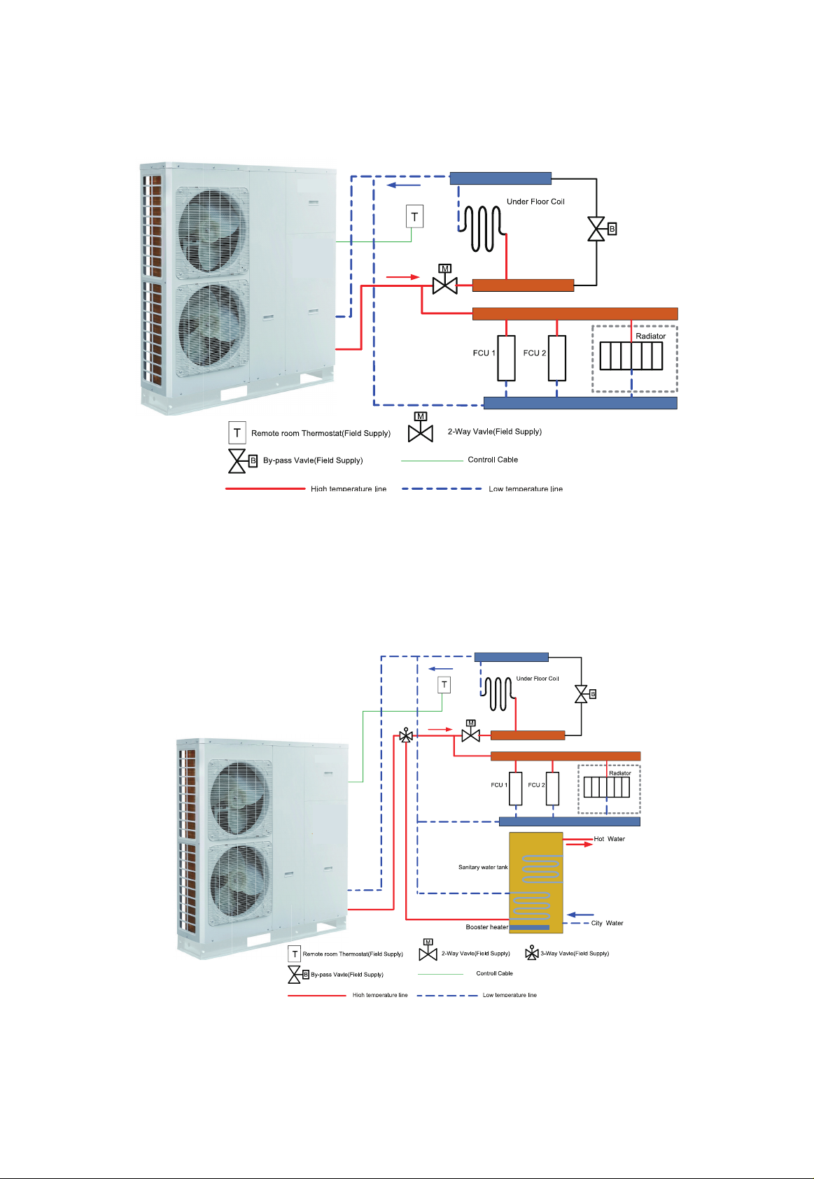
4. Installation Example
&$6(&RQQHFWLQJ+HDW(PLWWHUVIRU+HDWLQJDQG&RROLQJ8QGHUÀRRUORRS)DQ&RLO8QLWDQG5DGLDWRU
Notes
(a) 7KHWZRZD\YDOYHLVYHU\LPSRUWDQWWRSUHYHQWGHZFRQGHQVDWLRQRQWKHÀRRUDQG5DGLDWRUZKLOHFRROLQJ
PRGH
(b) 7\SHRIWKHUPRVWDWDQGVSHFL¿FDWLRQVKRXOGEHFRPSOLHGZLWKLQVWDOODWLRQRIWKLVPDQXDO
(c) The Bypass valve must be installed to secure enough water flow rate, and should be installed at the
FROOHFWRU
CASE 2: Connecting Sanitary Water Tank
Notes
(a) ,QWKLVFDVHWKUHHZD\YDOYHVKRXOGEHLQVWDOOHGDQGVKRXOGEHFRPSOLHGZLWKLQVWDOODWLRQRIWKLVPDQXDO
(b) Sanitary water tank should be equipped with internal electric heater to secure enough heat energy in the
YHU\FROGGD\V

12
CASE 3 : Connecting Solar thermal system
Notes
(a) 7ZRZD\YDOYHLVYHU\LPSRUWDQWWRSUHYHQWGHZFRQGHQVDWLRQRQWKHÀRRUDQG5DGLDWRUZKLOHFRROLQJPRGH
(b) 3-Way valve 1 is controlled by user,while the pool pump is actived, 3-Way valve 1 switches to
(c) SRROORRSZKLOHWKHSRROSXPSLVVKXWHGGRZQ:D\YDOYHVZLWFKHVWRXQGHUÀRRU)&8ORRS
(d) 3-Way valve 2 is automatic controlled by monobloc unit,while running water heating mode,3-Way valve 2
VZLWFKHVWRZDWHUWDQNORRSZKLOHUXQQLQJFRROLQJKHDWLQJPRGH:D\YDOYHVZLWFKHVWRXQGHUÀRRU)&8
loop.
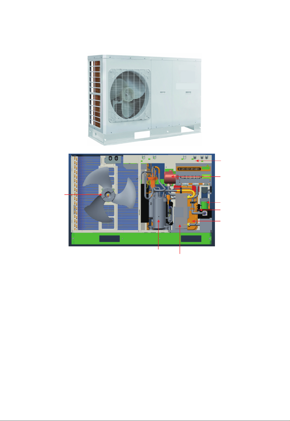
13
5. Main Components
0/RS-CQ8.0Pd/NaC-K,0/RS-CQ10Pd/NaC-K
'&)DQ0RWor
Control Box
Electric Heater
Water Pump
Expansion Tank
Plate Heat Exchanger
Compressor
Flow Switch

14
0/RS-CQ12Pd/NaC-M,0/RS-CQ14Pd/NaC-M
'&)DQ0RWRr
Control Box
Safety Valve
Air Vent
Electric Heater
Expansion Tank
Water Pum
Flow Switc
Plate Heat Exchanger
Flash Tank
Compressor

15
6. Installation Guideline of the Unit
6.1 Instruction to installation
Installation of the unit must be in accordance with national and local safety codes.
IInstallation quality will directly affect the normal use of the air conditioner unit. The user is prohibited from
installation. Please contact your dealer after buying this machine. Professional installation workers will provide
installation and test services according to installation manual.
'RQRWFRQQHFWWRSRZHUXQWLODOOLQVWDOODWLRQZRUNLVFRPSOHWHG
6.2 Installation of the Monobloc Unit
6.2.1 Selection of the Installation Location of the Monobloc Unit
7KHPRQREORFXQLWPXVWEHLQVWDOOHGRQD¿UPDQGVROLGVXSSRUW
Avoid placing the monobloc unit under window or between two constructions, hence to prevent normal operating
noise from entering the room.
$LUÀRZDWLQOHWDQGRXWOHWVKDOOQRWEHEORFNHG
,QVWDOODWDZHOOYHQWLODWHGSODFHVRWKDWWKHPDFKLQHFDQDEVRUEDQGGLVFKDUJHVXI¿FLHQWDLU
'RQRWLQVWDOODWDSODFHZKHUHÀDPPDEOHRUH[SORVLYHJRRGVH[LVWRUDSODFHVXEMHFWWRVHYHUHGXVWVDOW\IRJ
and polluted air.
6.2.2 Outline Dimensions of the Monobloc Unit
0/RS-CQ8.0Pd/NaC-K,0/RS-CQ10Pd/NaC-K
1390
412
361
388
890
16
0/RS-CQ12Pd/NaC-M,0/RS-CQ14Pd/NaC-M
367
340
1390
1430
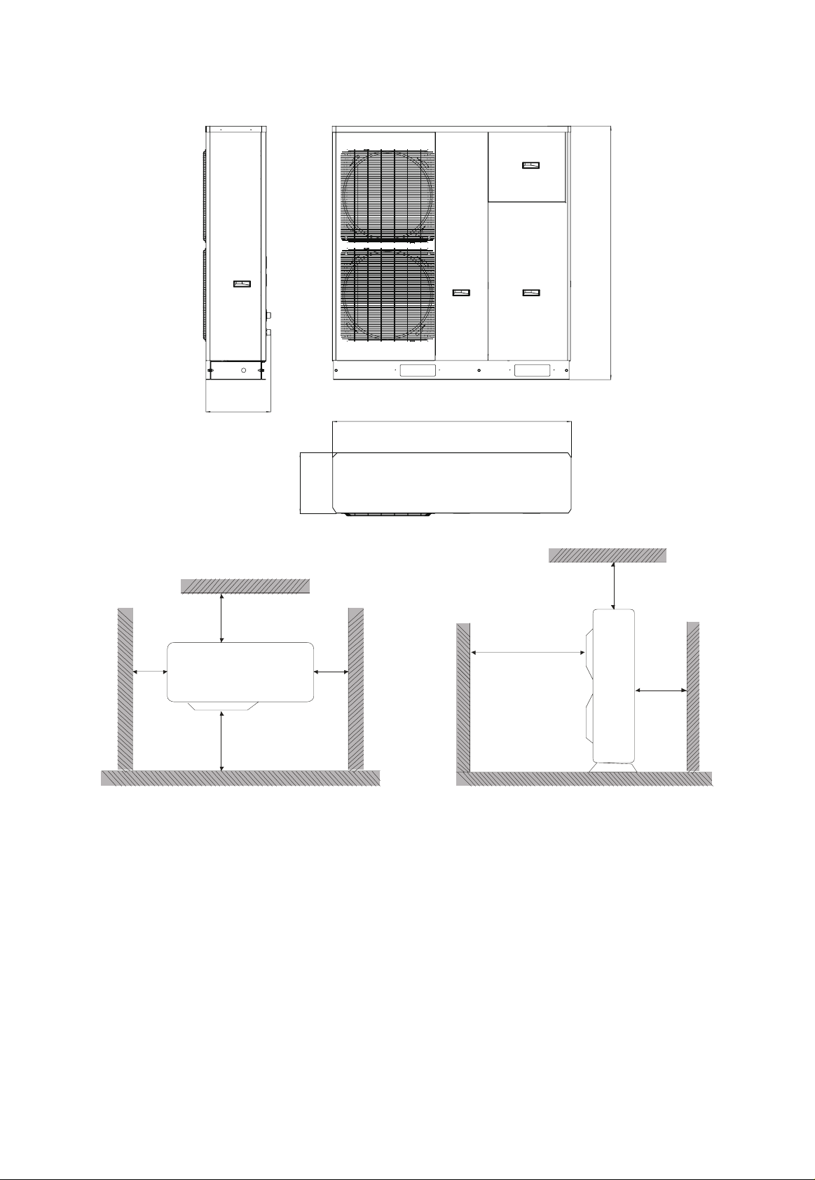
6.2.3 Space requirements for installation
˚1000
˚2000
˚
500
˚
500
˚
500
˚
500
˚
2000
6.2.4 Precautions on installation of the Monobloc Unit
When moving the monobloc unit, it is necessary to adopt 2 pieces of long enough rope to hand the unit from 4
directions. Included angle between the rope when hanging and moving must be 40°below to prevent center of the
unit from moving.
The monobloc unit should be installed on concrete base that is 10cm height.
Requirements on installation space dimension of unit’s bodies are shown in following drawing.
The monobloc unit must be lifted by using designated lifting hole. Take care to protect the unit during lift. To
avoid rusting, do not knock the metal parts.
This manual suits for next models
3
Table of contents
Other MegaLife Air Conditioner manuals


Popular Air Conditioner manuals by other brands


Panasonic
Panasonic CS-C12MKF-2 operating instructions

Panasonic
Panasonic CS-C18DKD Service manual

Defy
Defy 059 044 installation instructions

Premier
Premier E Series Installation and maintenance manual

Olimpia splendid
Olimpia splendid NovEcos Split 11 Instructions for installation, use and maintenance

Acson international
Acson international ADB200B2 manual