MegaLife ML-PC10AO-K5NNA1A User manual

Owner's Manual
Original Instructions
Portable air conditioner
Model: ML-PC10AO-K5NNA1A
ML-PH12AO-K5NNA1A
ML-PC12AO-K5NNA1A
Thank you for choosing our product.
Please read this Owner’s Manual carefully before operation and
retain it for future reference.
Content
Operation Notices
Safety precautions
.............................................................................................
Operation Environment
Parts Name
Operation Guide
Installation
.........................................................................................
Operation Introduction for Control Panel ...............................................................
Buttons on Remote Controller ...............................................................................
Introduction for Buttons on Remote Controller .......................................................
Double-hung sash window(Optional 1).................................................................
Clean and Maintenance
Malfunction
Malfunction analysis
Installation Notice
3
Using the remote controller ...................................................................................
4
Introduction for Icons on Display Screen ...............................................................
1
Installation in sash window(Optional 1) ................................................................
2
6
8
10
11
12
Function Introduction for Combination Buttons
Replacement of Batteries in Remote Controller
Maintenance
.....................................................
7
7
12
9
14
16
Sliding sash window (Optional 1)..........................................................................
17
....................................................
Installation and disassembly of heat discharge pipe (Optional 1&2).....................
18
Installation of Heat Discharge Pipe.......................................................................
19
Drain Water ..........................................................................................................
5
5
5
Installation Precaution ...........................................................................................
........................................................................................
Disassembly of Heat Discharge Pipe....................................................................
Attached Sheet
Electric Schematic Diagram...................................................................................
Preparation before Installation ...............................................................................
..........................................................................................................
20
21
21
Install Power cord Hooks ......................................................................................
Operation Test .......................................................................................................
Specialist’s Manual
................................................................................................ 22
..............................................................................................
Explanation of Symbols
WARNING
1.Damage the product due to improper use or misuse of the product;
2.Alter, change, maintain or use the product with other equipment without abiding
by the instruction manual of manufacturer;
3.After verification, the defect of product is directly caused by corrosive gas;
4.After verification, defects are due to improper operation during transportation of
product;
5.Operate, repair, maintain the unit without abiding by instruction manual or related
regulations;
6.After verification, the problem or dispute is caused by the quality specification or
performance of parts and components that produced by other manufacturers;
7.The damage is caused by natural calamities, bad using environment or force
majeure.
Exception Clauses
Manufacturer will bear no responsibilities when personal injury or property loss is
caused by the following reasons.
This symbol indicates the possibility of death or serious injury.
This symbol indicates the possibility of injury or damage to
property.
Indicates important but not hazard-related
information, used
to indicate risk of property damage.
If it needs to install, move or maintain the air conditioner, please contact dealer
or local service center to conduct it at first. Air conditioner must be installed,
moved or maintained by appointed unit. Otherwise, it may cause serious damage
or personal injury or death.
When refrigerant leaks or requires discharge during installation, maintenance, or
disassembly, it should be handled by certified professionals or otherwise in
compliance with local laws and regulations.
This appliance is not intended for use by persons (including children) with
reduced physical,
sensory
or mental capabilities or lack of experience and
knowledge, unless they have been given supervision or instruction concerning
use of the appliance by a person responsible for their safety.
Children should be supervised to ensure that they do not play with the appliance.
CAUTION
NOTICE
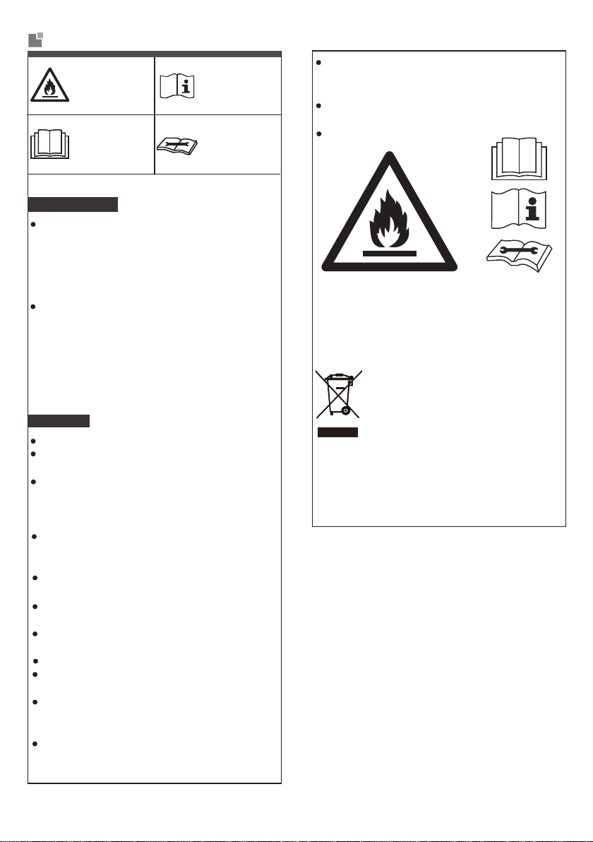
with flammable
gas R290. manual first.
Appliance filled appliance, read
the service ma-
The refrigerant
Before install the
appliance, read
the installation
WARNING
The Refrigerant
o a
2
nual first.
Before repair the
Appliance filled with flammable gas R290.
Appliance shall be installed,operated and stored
good thermodynamic features which lead t
R290:3
This marking indicates that this product
should not be disposed with other hou-
se hold wastes
throughout the EU. To
prevent possible harm to the environm-
ent or human health from uncontrolled
really high energy efficiency. The units there
fore need a less filling.
Frequency band(s) in which the radio equipment
operates: 2400MHz-2483.5MHz
Maximum radio-frequency power transmitted
in the frequency band(s) in which the radio
equipment operates: 20dBm
waste disposal,recycle it responsibly to promote
the sustainable reuse of material resources. To r-
eturn your used device, please use the return and
collection systems or contact the retailer where the
product was purchased. They can take this prod-
uct for environmental safe recycling.
in a room with a floor area larger than 11m .
The appliance shall be stored in a room without
continuously operating ignition sources.
(for example:open flames,an operating gas app-
liance or an operating electric heater.)
The appliance shall be stored in a well-ventilated
area where the room size corresponds to the
room area as specified for operation.
The appliance shall be stored so as to prevent
mechanical damage from occurring.
Ducts connected to an appliance shall not con-
tain an ignition source.
Keep any required ventilation openings clear of
obstruction.
Do not pierce or burn.
Be aware that refrigerants may not contain an
odour.
Do not use means to accelerate the defrosting
process or to clean,other than those recomm-
ended by the manufacturer.
Servicing shall be performed only as recomm-
ended by the manufacturer.
Should repair be necessary,contact your nearest
authorized Service Centre. Any repairs carried out
by unqualified personnel may be dangerous.
Compliance with national gas regulations shall
be observed.
Read specialist’s manual.
T
o realize the function of the air conditioner unit,
a special refrigerant circulates in the system.
The used refrigerant is the fluoride R290,which
is specially cleaned.
The refrigerant is flammable
and inodorous. Furthermore, it can leads to ex-
plosion
under certain conditions.
Compared to common refrigerants, R290 is a
nonpolluting refrigerant with no harm to the
ozonosphere. The influence upon the green-
house effect is also lower. R290 has got very
Before use the
appliance, read
the owner’s ma-
nual first.

WARNING
Make sure the power cord hasn’t been pressed by hard objects.
Do not pull or drag the power cord to pull out the power plug or
move the air conditioner.
Do not insert or pull out the power plug with wet hands.
Please use the grounded power. Make sure the grounding is reliable.
Children shall not play with the appliance.
Cleaning and user maintenance shall not be made by children
without supervision.
Before operation, please confirm whether power specification
complies with that on nameplate.
Before cleaning or maintaining the air conditioner, please turn off
air conditioner and pull out the power plug.
If the supply cord is damaged, it must be replaced by the
manufacturer or its service agent or a similarly qualified person
in order to avoid a hazard.
If abnormal condition occurs (e.g. burned smell), please
disconnect power at once and then contact local dealer.
When nobody is taking care of the unit, please turn it off and
remove the power plug or disconnect power.
Prohibit operating the unit in the bathroom or laundry room.
Far away from fire source, inflammable and explosive objects.
Children and disabled people are not allowed to use the
portable room air conditioner without supervision.
Keep children from playing or climbing on the air conditioner.
Do not splash or pour water on air conditioner. Otherwise, it may
cause short circuit or damage to air conditioner.
If drainage hose is used, ambient temperature can't be lower than
0 Otherwise, it will cause water leakage to air conditioner.
Prohibit operating heating equipment around the air conditioner.
Safety precautions
1
This appliance can be used by children aged from 8 years and
above and persons with reduced physical, sensory or mental
capabilities or lack of experience and knowledge if they have
been given supervision or instruction concerning use of the
appliance in a safe way and understand the hazards involved.
WARNING
Safety precautions
2
Operation Environment
at smooth and flat ground.
Prohibit inclining or turning over the air conditioner. If there’s abnor-
mity, please disconnect power immediately and contact dealer.
Avoid direct sunshine.
Do not put or hang dripping objects above the air conditioner.
Do not repair or disassemble the air conditioner by yourself.
Prohibit inserting any objects into the air conditioner.
Do not through sundries into the air duct. If there are sundries get
into the air duct, please contact the professionals to deal with it.
Do not use an extension cord.
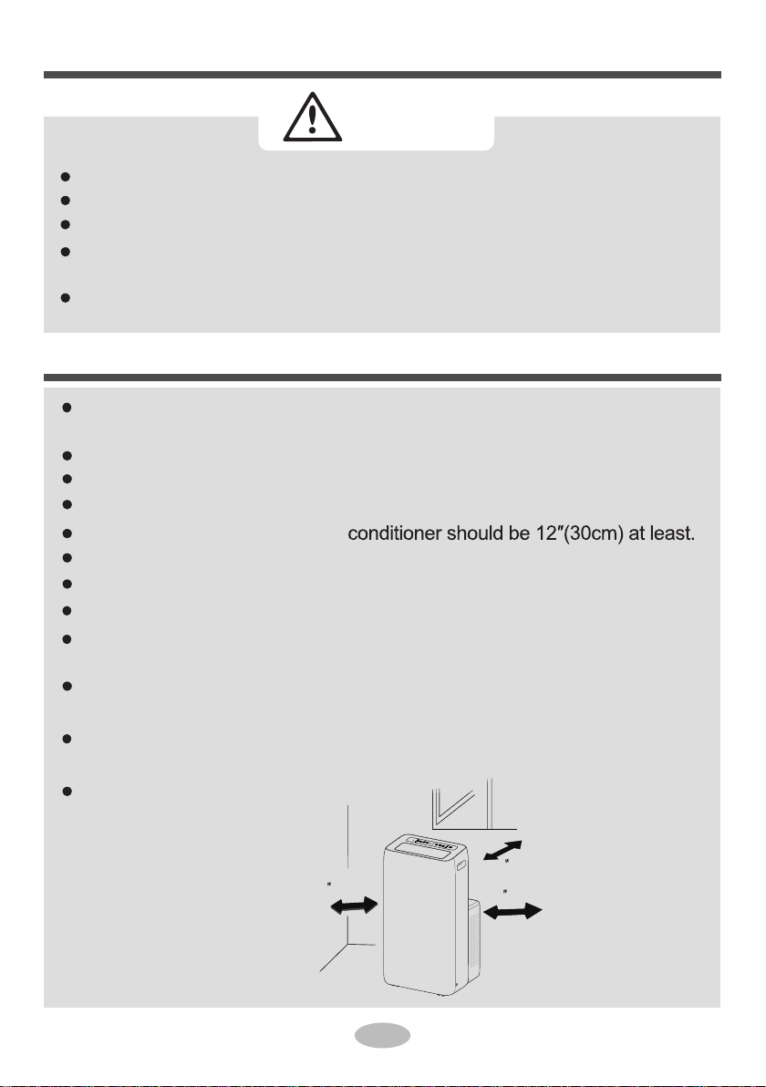
Please put the air conditioner at smooth and flat ground for operation
to avoid noise and vibration.
This air conditioner is equipped with castors. Castors should slide
Reserved space around the air
Do not operate the air conditioner at humid environment.
Please keep air inlet and air outlet clean, no obstacles.
During operation, close doors and windows to improve cooling effect.
The air conditioner must be operated within the temperature range:
16°C(61°F)~35°C(95°F).
The appliance is for indoor use only.
The appliance must be positioned so that the plug is accessible.
This air conditioner can only be used for family, not for commercial industry.
12 (30cm)
12 (30cm)
12 (30cm)

Parts name
1
232
3
7
5
6
FAN
OPER
7
Sleep Timer
8Health WiFi
10
9
Remote controller
Some installation accessories can't be discarded.
On/Off
Fan
Mode
Swing
●
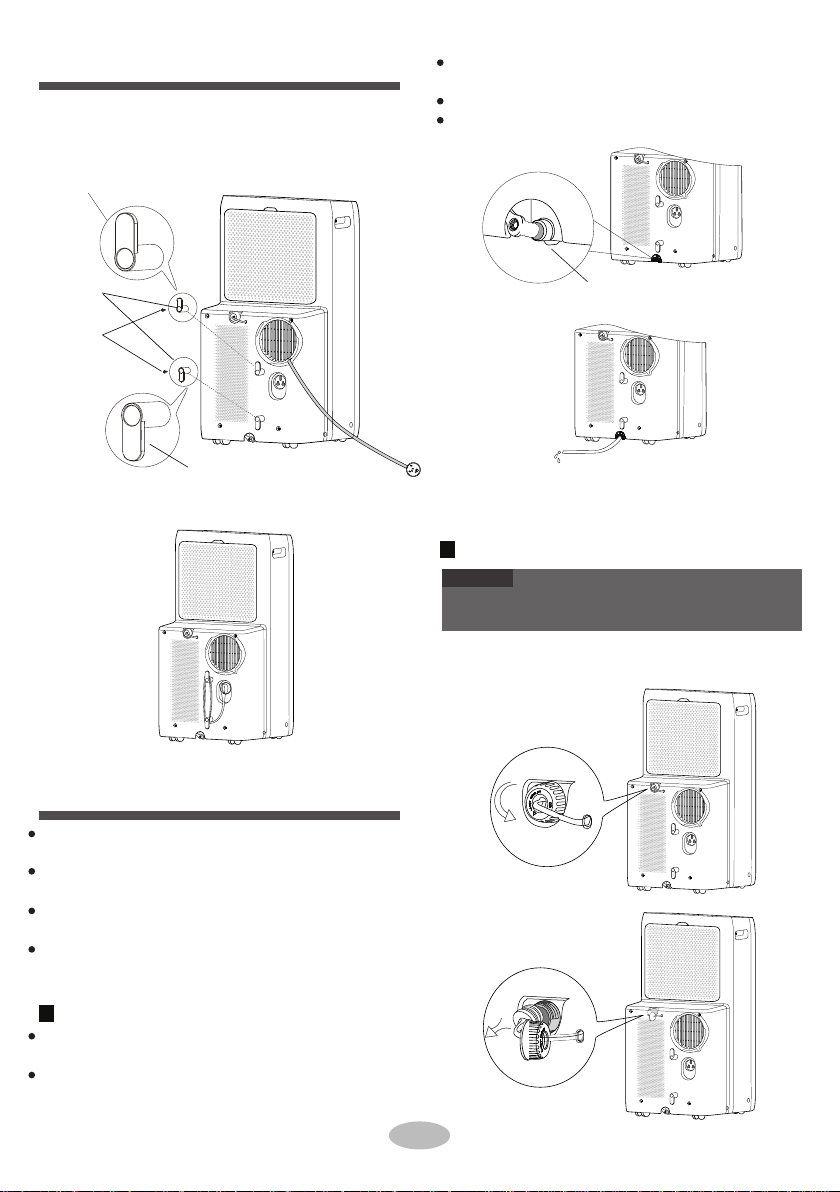
1Controller panel
Guide louver
NOTICE
4
5
6
Filter
Air inlet
Middle drainage port
Bottom drainage port

Operation Introduction for Control Panel
+ / - button
Swing indicator
Fan mode indicator
Swing button Dual-8 nixie tube
3
Operation of control panel
1ON/OFF button
Pressing this button can turn on or turn off
the air conditioner.
2+ / - button
Under cooling or heating mode, press “+” or
“-” button to increase or decrease set tem-
perature by 1°C (°F). Set temperature range
is 16°C(61°F)~30°C(86°F) .Under auto, dry
or fan mode, this button is invalid.
Fan button
auto fan
4Mode button
Press this button and the mode will circ
ulate
as:
medium speed
high speed
Cool
Heat
(Cool&Heat Unit only)
Dry
Fan
Name of control panel
WiFi indicator
Dry mode indicator
ON/OFF button
Timer indicator
Cool mode indicator
Fan button
Fan speed indicator
Mode button
Heat mode indicator
Timer button (Cool&Heat Unit only)
Press this button and the fan speed will circ-
ulate as:
low speed
After putting through the power, the air conditioner will give out a sound. After that, you can operate the
air conditioner by the control panel.
Under ON status, after each pressing of the button on control panel, the air
conditioner will give out a sound.
Meanwhile, corresponding indicator on control panel will be bright.
Under OFF status, dual-8 nixie tube on control panel won’t display.
Under ON status, dual-8 nixie tube on
control panel will display set temperature under cooling mode and Heating mode (Cool&Heat Unit only),
while it won’t display under other modes.
NOTICE
5Timer button
Press this button and the mode will circulate
according to below sequence:
tting will increase or decrease 1 hour by pressing
"+" or " - " button beyond 10 hours. After timer
Press timer button to enter into timer setting
mode. Under this mode, press "+" or "- " button
to adjust the timer setting. Timer setting will
increase or decrease 0.5 hour by pressing " + "
or " - " button within 10 hours, while timer se-
Cool: Under this mode, cool mode indicator is
bright. Dual-8 nixie tube displays set tempera-
ture. Temperature setting range is 16°C (61°F)
~30°C(86°F).
Dry: Under this mode, dry mode indicator is
bright. Dual-8 nixie tube won’t display.
Fan: Under this mode, the air conditioner only
blow fan. Fan mode indicator is bright. Dual-8
nixie tube won’t display.
Heat (Cool&Heat Unit only ) : Under this mode,
heating mode indicator is bright. Dual-8 nixie tube
displays set temperature. Temperature setting
range is 16°C(61°F)~30°C(86°F).

ation of control panel Buttons on remote controller
FAN
OPER
On/Off Mode
6Fan Swing
Sleep Timer
Health WiFi
Introduction for icons on display
screen
Using the remote controller
FAN
OPER
On/Off Mode
Fan Swing
Sleep Timer
Health WiFi
Oper
display
When the pattern is bright, it shows wifi opened
7Swing
Press this button,horizontal louver of air condit-
i
oner will swing up&down automatically.Single
press it to switchover between on and off.
This is a general use remote controller, it could be
used for the air conditioners
with multifunction; For
some function, which the model doesn't have, if pr-
ess the corresponding button on the remote contro-
ller that the unit will keep the original running status.
•
Set fan speed
Set temp.
Temp.
display type
CAUTION
Do not expose the receiver
window to direct sunlight.
This may adversely affect its
operation.
Use of certain fluorescent lamp in the same room may
interfere with transmission of the signal.
Do not leave the remote control in direct sunlight or ne-
ar a heater. Protect the rem
ote control from moisture
and shock.
•
•
•
Set time
TIMER ON / TIMER OFF
Light
Up & down swing
Child lock
Set temperature
WiFi function
Indoor ambient
temp.
Outdoor ambient
temp.
How to use the remote controller
Point the remote control toward the Signal receiver
and press the desired button. The unit generates
a beep when it receives the signal.
•Make sure nothing, such as curtains, blocks the
signal receiver window.
The signal effective distance is no more than 8m.
setting is finished, the unit will display temper-
ature if there’s no operation for 5s. If timer fun-
ction is started up, the upper indicator will keep
the display status. Others, it won’t be displayed.
Under timer mode, press timer button again to
cancel timer mode.
Turbo mode
Send signal
Auto mode
Cool mode
Dry mode
Fan mode
Heat mode
Sleep mode
8℃ heating function
Health mode
ventilation operation
I feel function
X-FAN function
Operation mode
NOTE
“ ” This is a general remote controller. Some models have this
function while some do not. Please refer to the actual models.

●
Auto Cool Dry Heat Speed 1 Speed 2
Speed 3
NOTE
●
●Cool:
●Dry:
●Fan Only:
● Heat:
●
Swing button
Introduction for buttons on
remote controller
Fan button
Press this button to turn “ON” & “OFF” swing.
ON/OFF button
Auto
There are 3 speeds for the Fan Speed of this model.
MODE button
Fan
Only
This is a general use remote controller. It could be
used for the air conditioner with multifunction. For the
functions which the model doesn't have, if press the
corresponding button on the remote controller, the
unit will keep the original running status.
Press this button to turn on the unit. Press this button
again to turn off the unit.
Under this mode, air conditioner operates under
cooling mode. Cooling indicator will be on. Press
“Fan Speed” button can adjust the fan speed.
+ / - button
Under this mode, air conditioner operates under
heating mode. Press “Fan Speed” button can
adjust the fan speed.(Cooling only unit won’t re-
ceive heating mode signal. If setting heat mode
with remote controller, press ON/OFF button can’t
start up the unit).
Under this mode, the unit runs in low fan speed
for dehumidification and the corresponding indicator
is on; under dry mode, the fan speed can not be
adjusted.
Under this mode, air conditioner will not cool or
heat, only blow wind. Fan indicator will be on. Press
“Fan Speed” button can adjust the fan speed.
Sleep button
Pressing “+” or “-” button once will increase or dec-
rease set temperature by 1°F(°C). Hold “+” or “-”
button for 2s, set temperature on remote controller
will change quickly.
Release the button after your required set te-
mperature is reached.
Timer button
Health button
(This function is not applicable for this model. )
Under ON status, press this button to set timer OFF;
Under OFF status, press this button to set timer ON.
Press this button once and the characters of HOUR
ON (OFF) will flash to be displayed. Meanwhile, pr-
ess “+” button or “-” button to adjust timer setting
(time will change quickly if holding “+” or “-” button)
Time setting range is 0.5~24hours. Press this button
again to confirm timer setting and the characters of
HOUR ON (OFF) will stop flashing. If the characters
are flashing but you haven’t press timer button,timer
setting status will be quit after 5s.If timer is confirmer,
press this button again to cancel timer.
NOTE
●
mode.
Press this button to select your required operation
Press this button to go into the Sleep operation mode.
Press it again to cancel this function. This function is
a
vailable in COOL, HEAT (Only for models with
heating
function) mode to maintain the most co-
mfortable temperature for you.
tton until the time is reached to your set time.
●
then back to Auto.
Auto:
Under this mode, the unit will operate automatic-
ally according to ex-factory setting. In this case,
set temperature cannot be adjusted.
Under timer setting status, after each pressing of
“+” or “-” button, time will increase or decrease 0.5h .
Hold “+” or “-” button, 2s later, time displayed on
dual-8 nixie tube will change quickly. Loosen the bu-
This button is used for setting Fan Speed in the
sequence that goes from AUTO,
, , to
Press this button to turn on or turn off the health
and scavenging functions in operation status. Press
this button for the first time to start scavenging function;
LCD displays " ". Press the button for the second
time to start health and scavenging functions simul-
taneously; LCD displays " " and " ". Press this

●
●This function is applicable to partial of models.
1. Press the back side of remote controller marked
2.
3. Reinstall the cover of battery box.
signal sender battery
reinstall
remove
Cover of battery box
●
●
●
●
●
●
●
Replacement of batteries
in remote controller
Light function
Introduction for buttons on
Under switch-on or switch-off state, you may hold
"+"and "FAN" buttons simultaneously to set the lamp
on or off and send the code. After being energized
the lamp is defaulted on.
with “ ”, as shown in the fig, and then push out
the cover of
battery box along the arrow direction.
Replace two 7# (AAA 1.5V) dry batteries, and make
sure the position of "+" polar and "-" polar are
correct.
As the signal will be interfered in the room with electronic
fluorescent lamp, conversion fluorescent lamp or wirel-
ess phone, please get closer to the air conditioner when
Function introduction for
remote controller
button for the third time to quit health and scaven-
ging functions simultaneously. Press the button for
the fourth time to start health function; LCD display
" ". Press this button again to repeat the operat-
ion above.
combination buttons
Temperature display switchover function
Under OFF status, press "-" and "Mode" buttons
simultaneously to switch temperature display betw-
een °C and °F
using the remote controller.
Replace new batteries of the same model when replace
ment is required.
When you don’t use remote controller for a long time,
please take out the batteries.
The batteries contain materials, which are hazardous
t
o the environment; they must be removed from the
appliance before it is scrapped and that they are
disposed of safely.
Do not ingest battery, Chemical Burn Hazard;
Keep new and used batteries away from children.
If the battery compartment does not close securely,
stop using the product and keep it away from children.
If you think batteries might have been swallowed or
placed inside any part of the body, seek immediate
medical attention.
The distance between signal sender and receiving
window should be no more than 8m, and there should
be no obstacles between them.
●
NOTICE
●This function is only available for some models.
WiFi button
Press "WiFi" button to turn on WiFi function, "WiFi"
icon will be displayed on the remote controller;
Hold "WiFi" button for 5s to turn off WiFi function
and "WiFi" icon will disappear.
Under off status, press "MODE" and "WiFi" buttons
simultaneously for 1s, WiFi module will restore factory
settings.

●
●
●
●
●
●
Clean and maintenance
WARNING
●
●
●
3.
Clean outer case:
melted with neutral abluent to clean
shady place to dry it. it and then put at
Clean grille:
Use cleaner or soft brush to clean it.
2.
40
°C(104°F)
Please deal with them through local recycle bin.
If you want to throw away the air conditioner,
please contact local division or consultant serv-
ice center for the correct disposal method.
Clean outer case and grille
1.
Clean filter
Use cleaner or water to clean the filter.If the filter
dirty(such as grease),is very use warm water
Install filter
After the filer is cleaned and dried, reinstall it well.
●
Clean heat discharge pipe
Checking before use-season
Checking after use-season
Notice for recovery
2.
3.
1.
4.
5.
6.
Remove the heat discharge pipe from air conditio-
ner, clean and dry it , and then reinstall it. (For the
method of installation and removal , please refer to
the instruction for "Installation and disassembly of
heat discharge pipe").
1.
2.
3.
4.
5.
Make sure there's no accumulated water in ch-
Many packing materials are recyclable materials.
If there's dust on the surface of outer
case, please use soft towel to wipe it.
If the outer case is very dirty (such as
grease), please use neutral abluent
to wipe it.
Clean filter
Remove the filter
Press the clasp as shown in the fig, and then
remove the filter ;
Disconnect power supply.
Clean filter and outer case.
Remove dust and sundries on the air conditioner.
Eliminate accumulated water in chassis (refer to
the section of "Drainage way" for details).
Check whether window bracket is damaged or not.
If yes, please contact dealer.
dition.
Check whether air inlets and air outlets are blocked.
Check whether plug and socket are in good con-
Check whether filter is clean.
Check whether batteries are installed in remote
controller.
Check whether joint, win taeh dna tekcarb wod
discharge pipe are installed tightly.
Check whether heat discharge pipe is damaged.
Long-time storage
If you don't use the air conditioner for a long time
,
please maintain it by following steps for good
performance:
assis and the heat discharge pipe is disassembled.
Pull out the plug and wrap the power cord.
Clean the air conditioner and pack it well to pr-
event dust.
Before cleaning the air conditioner, please turn
off the unit and disconnect power. Otherwise, it
may cause electric shock.
Do not wash air conditioner with water. Otherw-
ise, it may cause electric shock.
Do not use volatile liquid (such as thinner or gas)
to clean the air conditioner. Otherwise, it may
damage the appearance of air conditioner.
Do not use liquid or corrosive detergent clean
the appliance and do not splash water or other
liquid onto it, otherwise,it may damage the pla-
stic components, even cause electric shock.
NOTICE
●
●
The filter should be cleaned about once every three
months.If there’s much dust in the operation envir-
onment, you can increase clean frequency.
Do not dry the filter with fire or hair drier.Otherwise,
it may be deformed or catch fire.

Check items
9
Malfunction analysis
Phenomenon
Air conditio-
Move the remote co-
ntroller close to air
conditioner.
Turn off the fluoresc-
ence lamp and try it
again.
ner can't
operate
Power failure?
Is plug loose? Reinsert the plug.
Solution
Wait after power recovery.
Please check below items before asking for main-
tenance. If the malfunction still can’t be eliminated,
please contact local dealer or qualified professionals.
Whether the air
switch is tripped
off or fuse is burnt?
Ask professional pe-
rson to replace air
switch or fuse.
Is there malfunction
for the circuit?
Ask professional per-
son to replace circuit.
Poor cooling
(heating)
Is the power too low?
Whether the unit is
restarted up after st-
opping immediately?
Wait for 3min, and
then turn on the unit
again.
Wait after voltage is
resumed.
Clean the air filter.
Whether the air filter
is too dirty?
window.
Whether the set tem-
perature is proper?
Adjust the tempera-
ture.
Close door and
Air conditioner
Whether door and
window are closed?
can't receive
signal from
remote con-
troller or rem-
ote controller
is not sensible.
Whether the unit is
interfered seriously
(such as static pre-
ssure, unstable
voltage)?
Please pull out the
plug. Insert the plug
after about 3min, and
then turn on the unit.
Whether remote co-
ntroller is within the
receiving range?
Whether it's blocked
by obstacles? Remove the obstacles.
The receiving range
of remote controller
is 8m. Do not exced
this range.
Is sensitivity of rem-
ote controller low?
You can
heard the
"PAPA"
Check the batteries
of remote controller.
If the power is low,
please replace the
batteries.
sound of
Whether there's flu-
orescence lamp in
the room?
Whether the unit is
turned on or turned
off just now?
Heat expansion or
shrinkage for the
panel due to change
of temperature, which
cause friction sound.
There's off
flavour off-flavour source.
Eliminate the
Clean the filter.
There's abn-
ormal sound
during oper-
ation
there's off-flavour
source in the room,
such as furniture,
cigarette etc.
Disconnect power,
put through the power
again, and then turn
on the unit again.
Whether the unit is
interfered by thunder,
radio, etc?
1.Pour out the water inside chassis.
2.If "H8" still exits, please contact profess-
ional person to maintain the unit.
If the malfunction still occur, please co-3.
ntact our after-sales service center.
1.Check if the unit is under high-temperature
2.Check if the evaporator and condenser
■
●
Water leakage.
Power cord is overheating or damaged.
Abnormal sound during operation.
Off-flavor.
●
■
●
●
Do not repair or refit the air conditioner by yourself.
WARNING
■
If there’re following phenomenon,please turn off the
air conditioner and disconnect the power immediat-
ely,and then contact dealer immediately.
are
blocked by some objects; if yes, take
away the objects, power off the unit and
then energize it for operation.
and high-humidity environment; if ambient
temperature is too high, power off the unit
and
then energize it for operation after the
ambient
temperature drops to 35℃below.
Malfunction code
H8
E8、H3
If operate the air conditioner under abnormal conditi-
on,it may cause malfunction,electric shock or fire hazard.
Troubleshooting
Please contact qualified professionals for
service.
Error code
F1、F2 F4 F0
Phenomenon
Set tempe
r-
No air blowed
out from air
conditioner
Check items
Whether air outlet or
air inlet is blocked?
Solution
Eliminate the obstacles.
Under heating mode,
whether indoor temp-
erature increase set
temperature? (Cool
& Heat Unit only)
The unit will stop blo-
wing fan after reaching
set temperature.
ature can't
be adjusted.
In order to prevent cold
air, air conditioner will
delay for a while to be
started up, which is the
normal phenomenon.
It's the normal pheno-
menon. Air conditioner
is defrosting. After de-
frosting is finished, it
will resume operation.
Whether evaporator
is defrosted? (obser-
ve it by pulling out
the filter)
Temperature can't be
adjusted under auto
mode.
Whether the unit op-
erates under auto
mode?
Temperature setting
range: 16°C-30°C .
Whether the requir-
ed temperature
exceeds the temp-
erature setting range?
sound
You can heard
water-flowing
There's flowing sound
of refrigerant inside
the air conditioner,
which is the normal
phenomenon.
Whether the unit is
turned on or turned
off just now?
Whether heating mo-
de is started up just
now? (Cool & Heat
Unit only)
1
Installation Precaution
Requirement of air conditioner
1.
Requirements for electric connection
Safety precaution
2.
3. The place near coast area.
4. The place with oil or fumes in the air.
5. The place with sulfureted gas.
6.
7.
1.
Air inlet should be far away from obstacles and do
Selection of installation location
Basic requirement
Installing the unit in the following places may cause
malfunction. If it is unavoidable, please consult the
local dealer:
3.
emitted by the outdoor unit will not affect neighb-
orhood.
will affect the radiation of heat discharge pipe.
2. Select a location where the noise and outflow air
4.
not put any objects near air outlet. Otherwise, it
Please try your best to keep far away from fluor-
1.
The place with strong heat sources, vapors, fla-
2. According to the local safety regulations, use qu-
installing the unit.
alified power supply circuit.
3.
mmable or explosive gas,or volatile objects spread
in the air.
The place with high-frequency devices (such as
welding machine, medical equipment).
4.
escent lamp.
The appliance shall not be installed in the laundry.
5. Be sure to cut off the power supply before proce-
eding any work related to electricity and safety.
6. Do not put through the power before finishing in-
stallation.
7.
8.
For appliances with type Y attachment, the instr-
Must follow the electric safety regulations when
Other places with special circumstances.
It’s not allowed to be installed on the unstable or
motive base structure (such as truck) or in the
corrosive environment (such as chemical factory).
9. The grounding resistance should comply with na-
tional electric safety regulations.
10.
sheet:
11.with national wiring regulations.
To be in compliance with IEC 61000-3-11, impe-
dance value of power-supply system connected
0.13
ML-PC10AO-K5NNA1A
ML-PH12AO-K5NNA1A
ML-PC12AO-K5NNA1A
models
max |Zsys| unit:ohm
to product must be less than or e qual to the all-
owable maximum value of |Zsys| in the following
■
■
■
uctions shall contain the substance of the following.
If the supply cord is damaged,it must be replaced
by the manufacturer, its service agent or similarly
qualified persons in order to avoid a hazard.
Properly connect the live wire, neutral wire and
grounding wire of power socket.
The appliance shall be installed in accordance
The air conditioner is first class electric appliance.
It must be properly grounding with specialized gr-
ounding device by a professional. Please make
sure it is always grounded effectively, otherwise
it may cause electric shock.
The yellow-green wire or green wire in air conditi-
oner is grounding wire, which can't be used for
other purposes.
WARNING
Observe all governing codes and ordinances.
Do not use damaged or non-standard power cord.
Be caution during installation and maintenance. Pr-
ohibit incorrect operation to prevent electric shock,
casualty and other accidents.

1
Accessory list
User's manual
Battery
Preparation before Installation
●
Remote controller
Joint A
(AAA 1.5V)
Heat discharge pipe
NOTE
Check if the accessories are available before insta-
llation.
Drain connector Power cord hooks Screws
FAN
Fan Swing
Mode
OPER
Sleep
On/Off
Timer
Health WiFi
Optional 1
Mothproof net
Bracket Screw
Mounting plate
Fixed clip
Fixed base
Sponge B
Sponge A
Optional 3
Optional 2
Optional 4
Drainage hose
Tools needed for installation
Joint E
Joint H Joint D
Phillips head screwdriver
Plastic Cover
Flathead screwdriver
Saw
Tape measure
Scissors
Pencil
Rear clip
Rear clip
Window panel
Extension panel
Exhaust
cover
Adjustment
panel
●
1.
Drain Water
12
Install Power cord Hooks
NOTE
●
Remove the continuous drain cap 1 by turning it
counter clockwise then remove the rubber stopper
2 from the spout.
2
Drain water from the middle drainage port.
Drainage method
Wind the power cord around the power cord
hooks.
Water can be automatically emptied into a floor drain
by attaching 14mm inner diameter hose (not included).
the unit with screws (the direction of power cord
●Assemble the power cord hooks at the back of
hooks is as shown in following fig).
Remove the rubber plug of the bottom drainage
port to drain water.
After draining, insert the rubber plug.
Press ON/OFF button to restart.
To reach the maximum performance, it is not
recommended to drain water, during Cool mode.
It is recommended to use the middle drainage port
to drain water, during Dry mode.
It is recommended to use the bottom drainage port
to drain water, during Heat mode.
To drain water from the bottom drainage port when
the display shows "H8".
1
Drain water from the bottom drainage port.
Turn off the unit and pull out the plug from the
socket.
Place a water container under the bottom drainage
port, or move the machine to a place where it can
drain.
power cord hooks
screws
direction of power cord hooks is downward
direction of power cord hooks is upward
Bottom drainage port
13
Drain Water
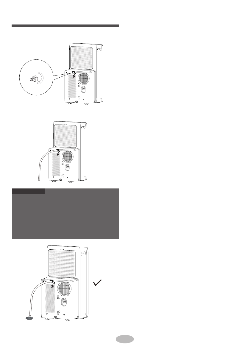
2. Screw the drain connector to(included in the
package) the spout by turning clockwise.
3.
ATTENTION:
Insert the drainage hose into drain connector.
When using continuous drainage option from the middle
hole, place portable on a level surface and make sure
garden hose is clear of any obstructions and is directed
d
ownward. Placing portable on an uneven surface or
improper hose installation may result in water filling up
the chassis and causing the unit to shut off. Empty water
in
the chassis if shut off occurs, then check portable lo-
cation and hose for proper setup.

14
Installation in sash window (Optional 1)
The dimension of the window kit as below.
(Unit:mm)
1.
3.
Operation instruction for Mounting Accessories of Window kit.
Attach the Mothproof net to the back side of the
Window Panel. Push the Mothproof net securely
into the Window Panel to ensure that is fit se-
curely.
720 770
770-1210
1210-1650
465
25
25
25 25 25
25
25
465
127
255
128 128
123 123
Window panel
Adjustment panel Extension panel
Exhaust cover
Fixed base Fixed base
Fixed base
Fixed base
Window
panel
Adjustment
panel
Fixed clip
Mounting
plate
Window
panel
Exhaust
cover
Fixed
base
Mothproof
net
Adjustment
panel
Fixed clip
Fixed clip
Mounting
plate
Mounting
plate
Extension
panel
Window
panel
Exhaust
cover
Fixed
base
Mothproof
net
Exhaust
cover
Fixed
base
Mothproof
net
2.Open the window and measure the width or
height inside the window frame.
width
height
15
For windows with inner width or height over
1210mm up to 1650mm. Use two fixed bases,
Adjustment Panel ,Extension panel, Mounting
plate and fixed clip.
Push one fixed base to the end of Window
Panel.
Attach with a fixed clip in the groove of the
Window Panel and a Mounting plate.
Insert Adjustment Panel to the end of Window
Panel, until the fixed clip connect the gap on the
Adjustment Panel.
Attach with a fixed clip in the groove of the
Extension panel and a Mounting plate.
Insert Extension Panel to the end of Adjustment
Panel, until the fixed clip connect the gap on the
Adjustment Panel.
Push fixed bases to the end of Extension panel.
Adjust the wide fix to the dimension of window
and screw down by a Mounting plate.
C)
1)
2)
3)
4)
5)
6)
7)
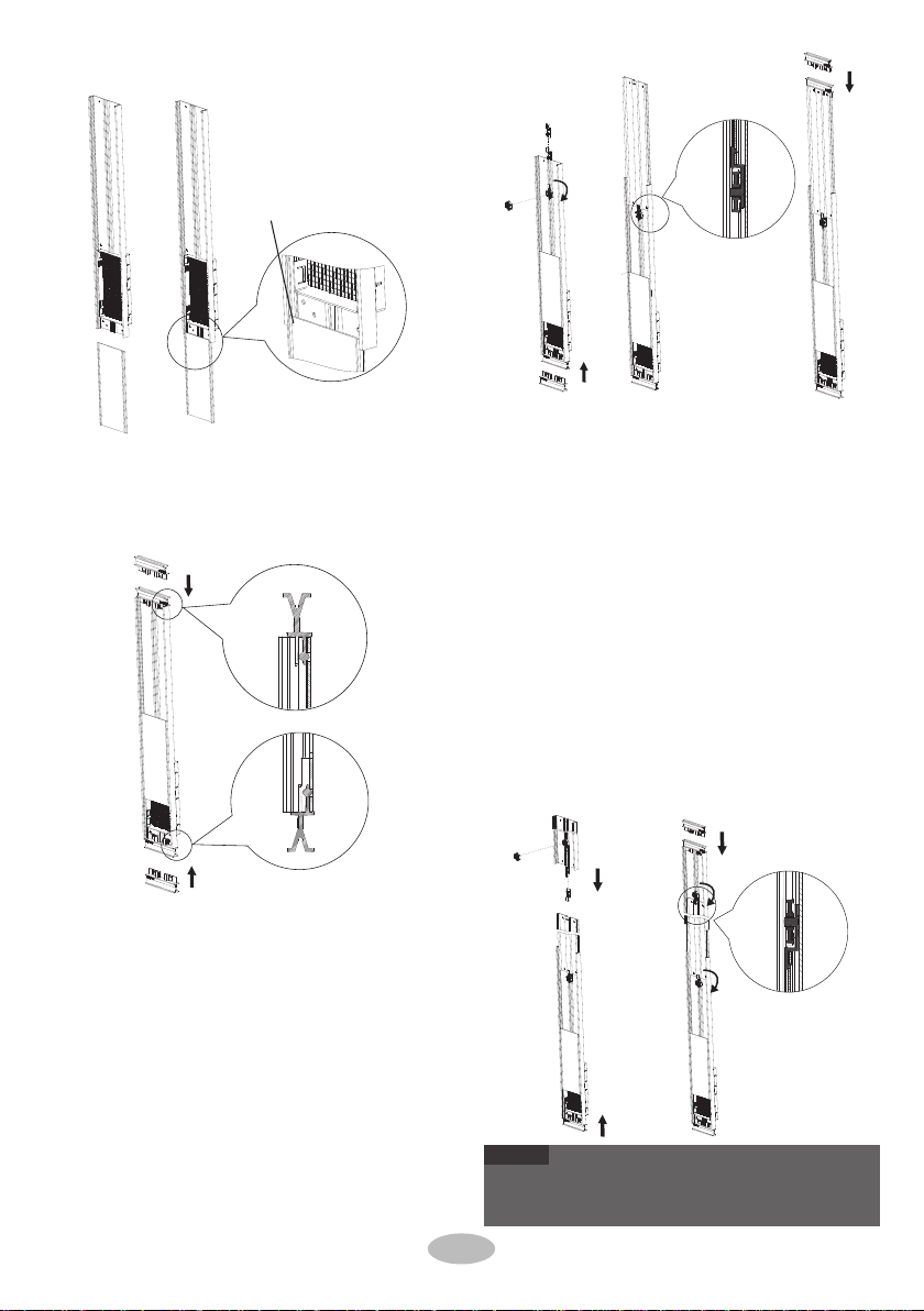
Assemble the window kit as below.5.
For windows with inner width or height of
770mm, push two fixed bases to the end of
Window Panel.
A)
For windows with inner width or height over
770mm up to 1210mm, use two fixed bases,
Adjustment Panel ,Fixed clip and Mounting
plate.
Push one fixed base to the end of Window
Panel.
Attach a fixed clip in the groove of the Window
Panel and a Mounting plate.
Insert Adjustment Panel to the end of Window
Panel, until the fixed clip connect the gap on the
Adjustment Panel.
Push fixed bases to the end of Adjustment
Panel.
Adjust the wide fix to window and screw down
by Mounting plate.
B)
1)
2)
3)
5)
4)
Insert the Exhaust cover to the Window Panel.4.
Insert the first groove
NOTE
●
If Extension Panel or Adjustment Panel are too long,
use a Pencil and Saw to cut panels to fit window
frame.
16
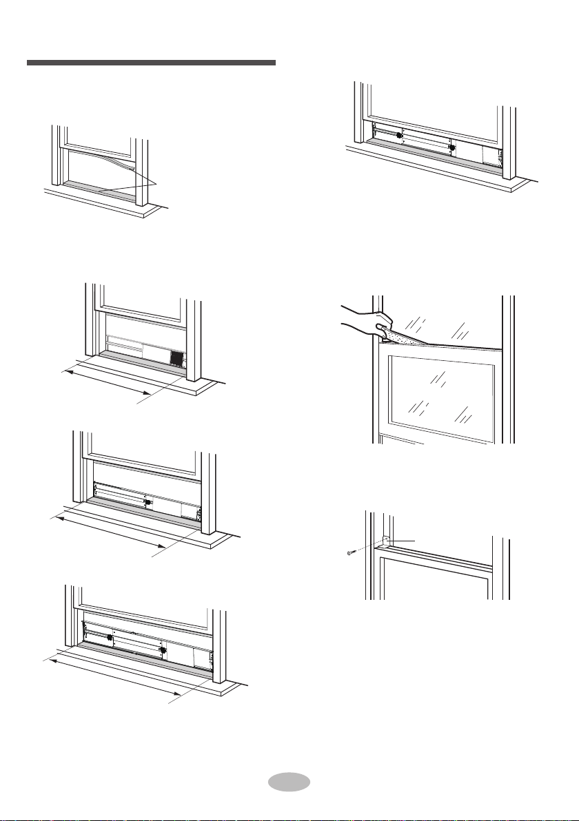
Please lay a tabular material underneath the
window panel in case you could not attach the
Rear clip properly due to the deep window sill.
Bracket
3.
4.
5. Attach the bracket with a screw.(Recommended)
Close the window sash securely against the
Window panel.
Stuff the Foam seal A between the glass and the
window to prevent air and insects from getting
into the room.
2. Attach the window panel to the window stool.
Make sure that the exhaust cover is attached to
the window panel.
770mm
770mm-1210mm
Double-hung sash window
(Optional 1)
1. Cut the Foam seal (adhesive type) to the proper
length and attach it to the window stool and to the
bottom of sash.
Foam seal (adhesive type)
1210mm-1650mm
This manual suits for next models
2
Table of contents
Other MegaLife Air Conditioner manuals


Popular Air Conditioner manuals by other brands


Olimpia splendid
Olimpia splendid DOLCECLIMA COMPACT Instructions for installation, use and maintenance

Dirna
Dirna MiniCool COMPACT 3.0 N&D User handbook

Sharp
Sharp AY-XM12CR Operation manual

Heat Controller
Heat Controller A-VMH18DC-1 Service Service manual

Whynter
Whynter HAC-100S user manual

BONAIRE
BONAIRE Durango 5300 owner's manual

Mitsubishi Electric
Mitsubishi Electric Mr. Slim PLH-1.6KKB installation manual

Comfee
Comfee GLACE 8C instruction manual

Mitsubishi Electric
Mitsubishi Electric MSZ-SF25VE operating instructions

LG
LG SN18SIV owner's manual

Lanaform
Lanaform Breezy Cube manual

Fujitsu
Fujitsu Airstage AJ 040LCLDH Series installation manual