MegaLife GOLD-PLUS 36000 BTU-H User manual

Owner's Manual
Original Instructions
Split Air Conditioner
CONTENTS
Safety precautions
.......................................................................................
01
...................................................................................................
05
.............................................
06
.............................................................
11
.........................................................................................
12
..............................................................................
14
............................................................................
17
.......................................................................................
19
Configuration of connection pipe
..................................................................
20
...............................................................................
10
Thank you for choosing our product.
Please read this Owner’s Manual carefully before operation and
retain it for future reference.
Parts name
Operation and introduction of remote controller
Clean and maintenance
Checked items before maintenance
Installation notice
Installation of indoor unit
Installation of outdoor unit
Test and operation
Notice:
Actual product may be different from graphics,
please refer to actual products.
Explanation of Symbols
WARNING
NOTICE
CAUTION
After verification, the defects are due to improper operation during transportation4.
5.
by the instruction manual of manufacturer;
3.After verification, the defect of product is directly caused by corrosive gas;
6.
7.
Exception Clauses
Manufacturer will bear no responsibilities when personal injury or property loss is
caused by the following reasons.
1.Damage the product due to improper use or misuse of the product;
2.Alter, change, maintain or use the product with other equipment without abiding
of product;
Operate, repair, maintain the unit without abiding by instruction manual or related
regulations;
After verification, the problem or dispute is caused by the quality specification or
performance of parts and components that produced by other manufacturers;
The damage is caused by natural calamities, bad using environment or force majeure.
This symbol indicates the possibility of injury or damage to
property.
Indicates important but not hazard-related information,
used
to indicate risk of property damage.
This symbol indicates the possibility of death or serious injury.
If it needs to install, move or maintain the air conditioner, please contact dealer
or local service center to conduct it at first. Air conditioner must be installed,
moved or maintained by appointed unit. Otherwise, it may cause serious damage
or personal injury or death.
When refrigerant leaks or requires discharge during installation, maintenance, or
disassembly, it should be handled by certified professionals or otherwise in
compliance with local laws and regulations.
This appliance is not intended for use by persons (including children) with
reduced physical, sensory or mental capabilities or lack of experience and
knowledge, unless they have been given supervision or instruction concerning
use of the appliance by a person responsible for their safety.
Children should be supervised to ensure that they do not play with the appliance.
Wireless frequency range:2412MHz – 2472MHz
Maximum Transmit Power:18.7dBm
Hereby, ML Electronics
, declares that this Air Conditioner is in
compliance with the essential requirement and other relevant provisions of RE Directive 2014/53/EU.
A copy of the full DoC is attached.
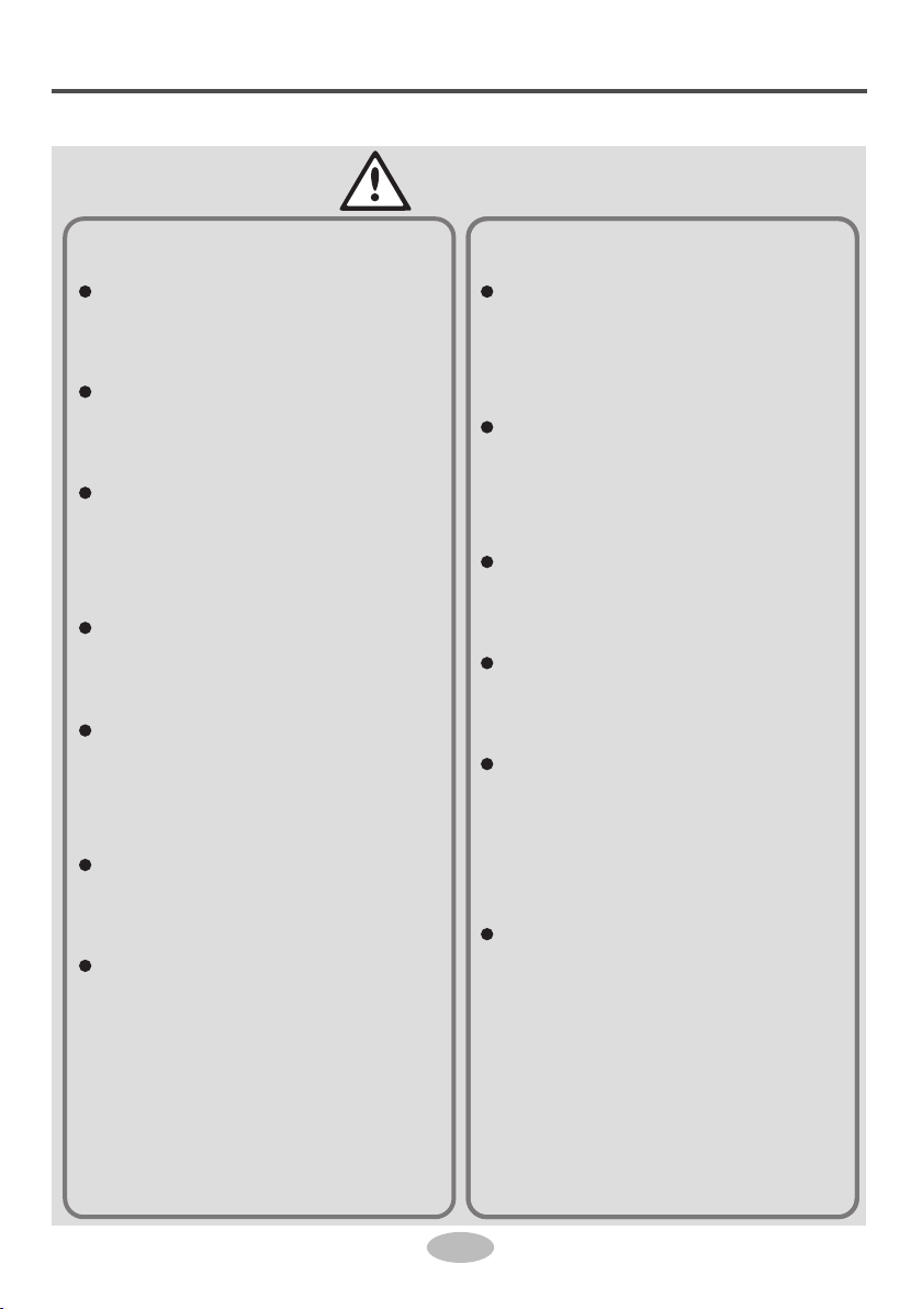
Safety precautions
Installation
1
WARNING
Installation or maintenance
must be performed by qua-
lified professionals.
The appliance shall be in-
stalled in accordance with
national wiring regulations.
According tothe local safe-
ty regulations, use quali-
fied power supply circuit
and circuit breaker.
All wires of indoor unit and
outdoor unit should be con-
nected by a professional.
Be sure to cut off the power
supply before proceeding
any work related to elec-
tricity and safety.
Make sure the power supp-
ly matches with the require-
ment of air conditioner.
Unstable power supply or
incorrect wiring may result
in electric shock, fire haza-
rd or malfunction. Please
install proper power supply
cables before using the air
conditioner.
The grounding resistance
should comply with nation-
al electric safety regula-
tions.
Air Conditioner should be
properly grounded. Inco-
rrect grounding may cause
electric shock.
Do not put through the
power before finishing in-
stallation.
Do install the circuit brea-
ker. If not, it may cause
malfunction.
An all-pole disconnection
switch having a contact se-
paration of at least 3mm in
all poles should be conne-
cted in fixed wiring.
Circuit breaker should be
included magnet buckle
and heating buckle func-
tion. It can protect the
overload and circuit-short.
Safety precautions
Installation
2
CAUTION
Instructions for installation
and use of this product are
provided by the manufac-
turer.
Select a location which is
out of reach for children
and far away from animals
or plants. If it is unavoid-
able, please add the fence
for safety purpose.
The indoor unit should be
installed close tothe wall.
Don't use unqualified pow-
er cord.
If the length of power con-
nection wire is insufficient,
please contact the supplier
for a new one.
The appliance must be po-
sitioned sothat the plug is
accessible.
For the air conditioner with
plug, the plug should be re-
achable after finishing in-
stallation.
For the air conditioner with-
out plug, a circuit breaker
must be installed in the
line.
The yellow-green wire in
air conditioner is ground-
ing wire, which can't be us-
ed for other purposes.
The air conditioner is the
first class electric applian-
ce. It must be properly gro-
under with specialized gr-
ounding device by a pro-
fessional. Please make
sure it is always ground-
ed effectively, otherwise it
may cause electric shock.
The temperature of refri-
gerant circuit will be high,
please keep the interconn-
ection cable away from the
copper tube.

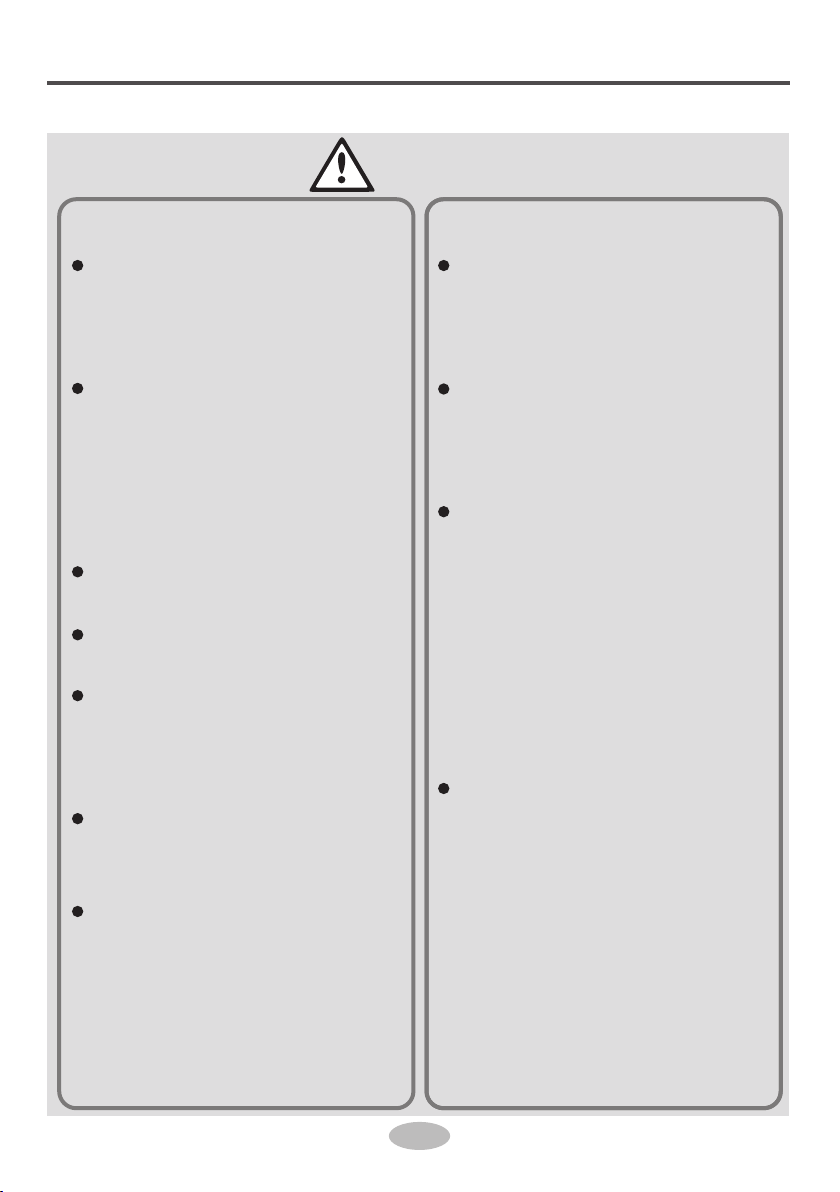
Safety precautions
Operation
and Maintenance
3
WARNING
This appliance can be used
by children aged from 8
years and above and per-
sons with reduced physi-
cal, sensory or mental ca-
pabilities or lack of expe-
rience and knowledge if
they have been given su-
pervision or instruction con-
cerning use of the applian-
ce in a safe way and un-
derstand the hazards in-
volved.
Children shall not play with
the appliance.
Cleaning and user main-
tenance shall not be made
by children without super-
vision.
If the supply cord is damag-
ed, it must be replaced by
the manufacturer, its ser-
vice agent or similarly qua-
lified persons in order to
avoid a hazard.
Do not connect air condi-
tioner to multi-purpose soc-
ket. Otherwise, it may cau-
se fire hazard.
Do disconnect power supp-
ly when cleaning air condi-
tioner. Otherwise, it may
cause electric shock.
Do not wash the air condi-
tioner with water to avoid
electric shock.
Do not spray water on in-
door unit. It may cause ele-
ctric shock or malfunction.
Do not repair air condition-
er by yourself. It may cause
electric shock or damage.
Please contact dealer when
you need to repair air con-
ditioner.
After removing the filter, do
not touch fins to avoid in-
jury.
Do not extend fingers or
objects into air inlet or air
outlet. It may cause person-
al injury or damage.

Safety precautions
Operation
and Maintenance
4
CAUTION
Do not spill water on the re-
mote controller, otherwise
the remote controller may
be broken.
Do not use fire or hair dry-
er to dry the filter to avoid
deformation or fire hazard.
Do not block air outlet or
air inlet. It may cause mal-
function.
Do not step on top panel of
outdoor unit, or put heavy
objects. It may cause dam-
age or personal injury.
When below phenomenon
occurs, please turn off air
conditioner and disconnect
power immediately, and
then contact the dealer or
qualified professionals for
service.
Power cord is overheat-
ing or damaged.
There’s abnormal sound
during operation.
Circuit breaker trips off
frequently.
Air conditioner gives off
burning smell.
Indoor unit is leaking.

5
Ɣ
Ɣ
Parts name
Indoor Unit Outdoor Unit
Display
7KLVLVWKHJHQHUDOLQWURGXFWLRQDQGWKHFRORURI
LQGLFDWRULVRQO\IRUUHIHUHQFH3OHDVHUHIHUWRWKH
DFWXDOGLVSOD\
'LVSOD\FRQWHQWPD\EHGLIIHUHQWIURPWKHDFWXDO
3OHDVHUHIHUWRWKHDFWXDOGLVSOD\
,IUHPRWHFRQWUROOHULVORVWRUGDPDJHGSOHDVH
XVHDX[EXWWRQWRWXUQRQRUWXUQRIIWKHDLU
FRQGLWLRQHU7KHRSHUDWLRQLQGHWDLOVLVDV
EHORZ$VVKRZQLQWKHILJXUHRSHQSDQHODQG
SUHVVDX[EXWWRQWRWXUQRIIWKHDLUFRQGLWLRQHU
:KHQWKHDLUFRQGLWLRQHULVWXUQHGRQLWZLOO
RSHUDWHXQGHUDXWRPRGH
Notice
Ɣ
$FWXDOSURGXFWPD\EHGLIIHUHQWIURPDERYHJUDSKLFV
SOHDVHUHIHUWRDFWXDOSURGXFW
Ŷ
7HPSLQGLFDWRU
'U\PRGH
3RZHULQGLFDWRU
+HDWPRGH
&RROPRGH
R
R:UHGLQGLFDWRU
RQO\IRUKHDWPRGHO
W:ZKLWHLQGLFDWRU
W
GG:JUHHQLQGLFDWRU
OO:RUDQJHLQGLFDWRU
Notice
DX[EXWWRQ
DLULQOHW SDQHO ILOWHU
KRUL]RQWDOORXYHU
DLURXWOHW
air inlet
air outlet

6
8ȭheating function
Set temperature
Scavenging function
Set time
X-FAN function
WiFi function
Light
Set temp.
Outdoor ambient
temp.
Indoor ambient
temp.
Sleep mode
Health mode
I feel
TIMER ON / TIMER OFF
Auto mode
Cool mode
Dry mode
Fan mode
Up & down swing
Child lock
Send signal
Turbo mode
Heat mode
Operation mode
Set fan speed
Temp.
display type
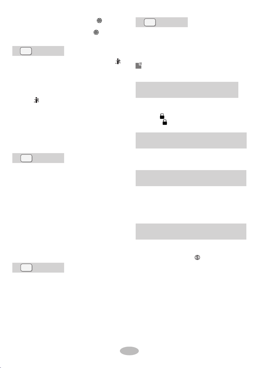
Introduction for icons on display
screen
Buttons on remote controller
Operation and introduction of
remote controller
Fan Swing
ModeOn/Off
Sleep Temp
Turbo
WiFi Light
Timer I Feel

This function indicates that moisture on evaporator of
indoor unit will be blowed after the unit is stopped to
avoid mould.
Having set X-FAN function on: After turning off the unit
by pressing ON/OFF button indoor fan will continue
running for a few minutes. at low speed. In this period,
Hold fan speed button for 2s to stop indoor fan directly.
Having set X-FAN function off: After turning off the unit
by pressing ON/OFF button, the complete unit will be
off directly.
This is a general use remote controller. It could be
used for the air conditioner with multifunction. For the
functions which the model doesn't have, if press the
corresponding button on the remote controller, the
unit will keep the original running status.
After putting through the power, the air conditioner
will give out a sound. Power indicator " " is ON.
After that, you can operate the air conditioner by
using remote controller.
Under on status, pressing the button on the remote
controller, the signal icon " " on the display of
remote controller will blink once and the air condition-
er will give out a "di"sound, which means the signal
has been sent to the air conditioner.
●
●
●
●
button
Swing
Mode
Sleep
button
Heat mode: Only for models with heating function.
button
●Outdoor temperature display is not available for some
Turbo button
Under cool or heat mode, press this button to turn
7
Introduction for buttons on
remote controller
button
Press ▲ / ▼ button to increase / decrease set tem-
perature. In AUTO mode, set temperature is not ad-
justable.
When setting Timer On or Timer Off, press "▲" or
"▼" button to adjust the time.
button
Press this button to set up & down swing angle.
button
Under Cool, Heat mode, press this button to turn
on Sleep function.
Press this button again to cancel Sleep function.
Under Fan, Dry and Auto modes, this function is
unavailable.
On/Off
Press this button to turn on the unit. Press this button
again to turn off the unit.
button
Notice
●
Temp
Press this button, you can see indoor set tempera-
ture, indoor ambient temperature on indoor unit's
display. The setting on remote controller is selected
circularly as below:
no display
Fan
This button is used for setting Fan Speed in the
sequence that goes from AUTO, ,, to ,
then back to Auto.
Notice
●
Notice
Fan speed under dry mode is low speed.
X-FANfunction:Hold fan speed button for 2s in
COOL or DRY mode, the icon
"
"
is displayed and
the indoor fan will continue operation for a few minutes
in order to dry the indoor unit even though you have
turned off the unit. After energization, X-FANOFF is
defaulted. X-FAN is not available in AUTO, FAN or
HEAT mode.
Notice
models. Atthat time, indoor unit receives " " signal,
while it displays indoor set temperature.
Each time you press this button, a mode is selected
in a sequence that goes from AUTO, COOL, DRY,
FAN, and HEAT, as the following:
AUTO COOL DRY FAN HEAT
●
●
8
Ɣ
Ɣ
Ɣ7KLVIXQFWLRQLVRQO\DYDLODEOHIRUVRPHPRGHOV
UQGHUONVWDWXs,SUHVVWhisEXWWRQWRsHWWiPHU
2))8QGHU2))sWDWXsSUHssWhisEXWWRQWRsHW
WLPHU21
EXWWRQ
TLPHU
EXWWRQ
EXWWRQ
/LJKW
ZLOOVWRSIODVKLQJ
,IWhHFKDUDFWHUsDUHIODsKLQgEXW\RXhDYHQ'WSUHss
WLPHUEXWWRQWLPHUsHWWLQJsWDWXsZLOOEHTXLWDIWHU
5sIIWLPHUisFRQILUPHU,SUHVVWhisEXWWRQDJDLQ
WRFDQFHOWLPHU
PUHVVWhisEXWWRQRQFHDQGWhHFhDUDFWHUVRI
HOURON(OFF)ZLOOIODVhWREHGLVSOD\HG0HDQ-
ZKLOH,SUHss"Ÿ"EXWWRQRU"ź"EXWWRQWRDGMXsW
WLPHUVHWWLQJ(WLPHZLOOFKDQJHTXLFNO\iIKROGLQg
"Ÿ"RU"ź"EXWWRQ)TLPHsHWWLQgUDQJHis05~
KRXUV3UHVVWKLVEXWWRQDJDLQWRFRQILUPWLPHU
sHWWLQgDQGWhHFKDUDFWHUsRIHOURON(OFF)
PUHssWhisEXWWRQWRWXUQRQWhHGLsSOD\'sOLJhWDQG
SUHssWhisEXWWRQDJDLQWRWXUQRIIWKHGisSOD\s
OLJKW
&RPELQDWLRQRI"ŸDQGźEXWWRQV
$ERXWFKLOGORFN
Function introduction for
combination buttons
AWXQiWOFF,SUHss"MODE"DQG"ź"EXWWRQVVLP-
XOWDQHRXVO\WRVZLWFKEHWZHHQ&DQG)
PUHss"Ÿ"DQG"ź"EXWWRQssLPXOWDQHRXsO\3sWR
ORFNRUXQORFNWhHNH\SDG,IWhHUHPRWHFRQWUROOHU
isORFNHG,isGisSOD\HGIQWhiVFDsH,SUHssLQg
DQ\EXWWRQEOLQNVWKUHHWLPHV
&RPELQDWLRQRI"MODE"DQG"ź"EXWWRQs
AERXWswiWFhEHWZHHQFDKUHQKHiWDQGFHQWLJUDGH
PUHVs7EMP"DQG7IMER"VLPXOWDQHRXVO\iQCOOL
PRGHWRVWDUWHQHUJ\VDYLQJIXQFWLRQ
NixLHWXEHRQWKHUHPRWHFRQWUROOHUGLsSOD\V"SE"
5HSHDWWKHRSHUDWLRQWRTXLWWKHIXQFWLRQ
&RPELQDWLRQRI7EMP"DQG7IMER"EXWWRQs
$ERXW(QHUJ\VDYLQJ)XQFWLRQ
EXWWRQ
&RPELQDWLRQRI7EMP"DQG7IMER"EXWWRQs
$ERXW&+HDWLQJ)XQFWLRQ
PUHVV7EM3DQG7IMERsiPXOWDQHRXVO\LQHEAT
PRGHWRsWDUW8C+HDWLQgFXQFWLRQNixiHWXEHRQWhH
UHPRWHFRQWUROOHUGisSOD\VDQGDsHOHFWHGWHP-
SHUDWXUHRI&)LI)DKUHQKHLWLVDGRSWHG
5HSHDWWKHRSHUDWLRQWRTXLWWKHIXQFWLRQ
,)HHO
WiFi
WKHQ:iFiIXQFWLRQiVWXUQHGRQ:iFiiFRQZLOO
EHGLsSOD\HGRQWKHUHPRWHFRQWUROOHUZKHQ:L)L
IXQFWLRQLVWXUQHGRII:L)LLFRQZLOOGLVDSSHDU
+RZWRWXUQRQWiFi:PUHVV:L)L"EXWWRQWRWXUQ
RQ:L)LIXQFWLRQ
+RZWRWXUQRII:iFi:+ROG:iFiEXWWRQIRU5sWR
WXUQRII:L)LIXQFWLRQ
8QGHURIIVWDWXVSUHVVMOD(DQG:iFi
EXWWRQVVLPXOWDQHRXVO\IRU1s:iFiPRGXOHZLOO
UHVWRUHIDFWRU\VHWWLQJV
PUHssWhisEXWWRQWRsWDUW,)(ELIXQFWLRQDQG"
ZLOOEHGLsSOD\HGRQWKHUHPRWHFRQWUROOHUAIWHU
WhiVIXQFWLRQiVsHWWhHUHPRWHFRQWUROOHUZLOOsHQG
WhHGHWHFWHGDPELHQWWHPSHUDWXUHWRWhHFRQWUROOHU
DQGWhHXQiWZLOODXWRPDWiFDOO\DGMXsWWhHLQGRRU
WHPSHUDWXUHDFFRUGLQgWRWhHGHWHFWHGWHPSHUD-
WXUHPUHssWhisEXWWRQDJDLQWRFORsH,)((LIXQF-
WLRQDQGZLOOGLVDSSHDU
POHDsHpXWWhHUHPRWHFRQWUROOHUQHDUXsHUwhHQ
WhisIXQFWLRQiVVHWDRQRWSXWWKHUHPRWHFRQWURO-
OHUQHDUWhHREMHFWRIhighWHPSHUDWXUHRUORwWHP-
pHUDWXUHLQRUGHUWRDYRLGGHWHFWiQgiQDFFXUDWH
DPELHQWWHPSHUDWXUHWKHQ,)(ELIXQFWLRQis
WXUQHGRQWhHUHPRWHFRQWUROOHUsKRXOGEHpXW
wiWhiQWhHDUHDZKHUHLQGRRUXQiWFDQUHFHLYHWhH
VLJQDOVHQWE\WKHUHPRWHFRQWUROOHU
DJDiQWRHxiWWXUERIXQFWiRQDQG"iFRQwiOO
GLVDSSHDU
WRqXiFNFRRORUqXiFNhHDWPRGHiFRQis
GispOD\HGRQUHPRWHFRQWUROOHUPUHssWhisEXWWRQ
9
'XULQJRSHUDWLRQSRLQWWKHUHPRWHFRQWUROVLJQDO
VHQGHUDWWKHUHFHLYLQJZLQGRZRQLQGRRUXQLW
7KHGLVWDQFHEHWZHHQVLJQDOVHQGHUDQGUHFHLYLQJ
ZLQGRZVKRXOGEHQRPRUHWKDQPDQGWKHUH
VKRXOGEHQRREVWDFOHVEHWZHHQWKHP
6LJQDOPD\EHLQWHUIHUHGHDVLO\LQWKHURRPZKHUH
WKHUHLVÀXRUHVFHQWODPSRUZLUHOHVVWHOHSKRQH
UHPRWHFRQWUROOHUVKRXOGEHFORVHWRLQGRRUXQLW
GXULQJRSHUDWLRQ
5HSODFHQHZEDWWHULHVRIWKHVDPHPRGHOZKHQ
UHSODFHPHQWLVUHTXLUHG
:KHQ\RXGRQWXVHUHPRWHFRQWUROOHUIRUDORQJWLPH
SOHDVHWDNHRXWWKHEDWWHULHV
,IWKHGLVSOD\RQUHPRWHFRQWUROOHULVIX]]\RUWKHUHV
QRGLVSOD\SOHDVHUHSODFHEDWWHULHV
Ɣ
Ɣ
Ɣ
Ɣ
Ɣ
Ɣ
Notice
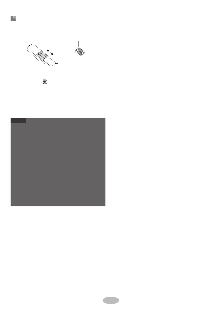
Replacement of batteries in
remote controller
3UHVVWKHEDFNVLGHRIUHPRWHFRQWUROOHU
PDUNHGZLWKDVVKRZQLQWKHILJDQGWKHQ
SXVKRXWWKHFRYHURIEDWWHU\ER[DORQJWKH
DUURZGLUHFWLRQ
5HSODFHWZR$$$9GU\EDWWHULHVDQG
PDNHVXUHWKHSRVLWLRQRISRODUDQGSRODU
DUHFRUUHFW
5HLQVWDOOWKHFRYHURIEDWWHU\ER[
EDWWHU\
UHPRYH
UHLQVWDOO
&RYHURIEDWWHU\ER[
VLJQDOVHQGHU
Clean and maintenance
Ŷ
2.
Ŷ
2.
4.
WARNING
WARNING
Please contact qualified professionals for
service.
Ŷ
Ŷ
Ŷ
Ŷ
Ŷ
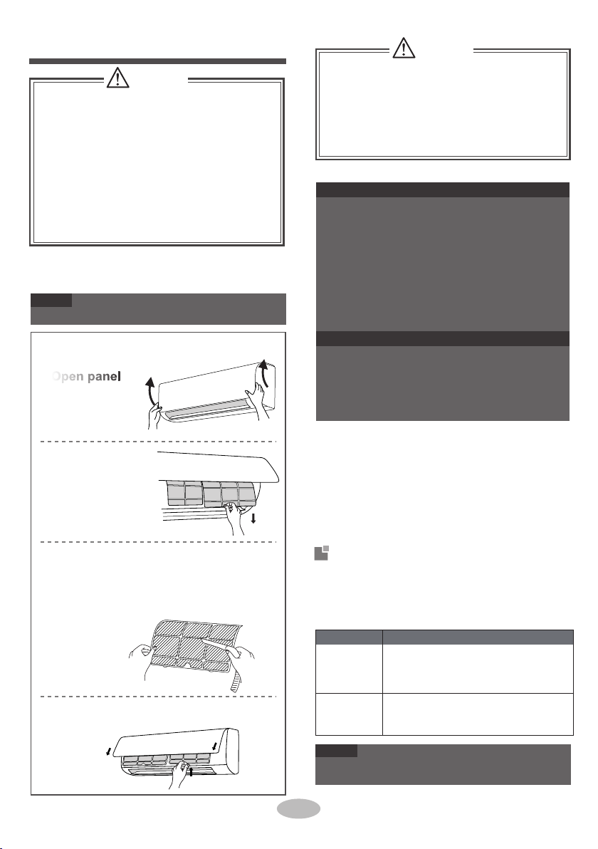
Clean filter
1.
Notice: Checking after use-season
Check whether air inlets and air outlets are bl-
Do not remove the panel when cleaning it.
Error Code
Error code
3.
Ɣ
Ɣ
F2
Notice
Ɣ
Notice
Ɣ
3.
Open panel
Pull out the panel
to a certain angle
as shown in the fig.
4.
E8
1.
1.
2.
3.
Remove filter
Remove the filter as
indicated in the fig.
Notice: Checking before use-season
Troubleshooting
C5,F0,F1,
U8,H6,H3,
Notice for recovery
2.
E1,E5,E6,
1.
Install filter
Install the filter and then close the panel cover
tightly.
If there're other error codes, please contact qu-
alified professionals for service.
10
ocked.
Check whether air switch, plug and socket are
Clean surface of indoor unit
When the surface of indoor unit is dirty, it is recomm-
ended to use a soft dry cloth or wet cloth to wipe it.
Disconnect power supply.
Clean filter and indoor unit’s panel.
Many packing materials are recyclable mate-
5.Check whether drainage pipe is damaged.
Check whether mounting bracke t for outdo
or
unit is damaged or corroded. If yes, please
contact dealer.
in good condition.
Check whether filter is clean.
Check whether mounting bracket for outdoor
unit is damaged or corroded . If yes, please
contact dealer.
The filter should be cleaned every three months.
If there is much dust in the operation environme-
nt, clean frequency can be increased.
After removing the filter, do not touch fins to
avoid injury.
Do not use fire or hair dryer to dry the filter to
avoid deformation or fire hazard.
When air conditioner status is abnor mal, tempe-
rature indicator on indoor unit will blink to display
corresponding error code. Please refer to below
list for identification of error code.
e t a i r po r ppan imeh tesops i desae l P. s l a i r
recycling unit.
esae l p, r eno i t i dnocr i aeh tesops i do t t nawuoyf I
contact local dealer or consultant service center
for the correct disposal method.
It can be eliminated after restarting the unit.
If not, please contact qualified professionals
for service.
Clean filter
Use dust catcher or water to clean the filter.
When the filter is very dirty, use the water
(below 45℃) to clean it , and then put it in a
shady and cool place to dry.
Turn off the air conditioner and disconnect the
power before cleaning the air conditioner to av-
oid electric shock.
Do not wash the air conditioner with water to
avoid electric shock.
Do not use volatile liquid to clean the air
conditioner.
Do not use liquid or corrosive detergent to clean
the appliance and do not splash water or other
liquid onto it, otherwise, it may damage the
plastic components , even cause electric shock.
Phenomenon Solution
Checked items before
maintenance
Eliminate the odour
source. Clean the
filter.
Unit is operating un-
der auto mode?
Voltage is too low?
Your required temp-
erature exceeds the
set temperature
range?
Wait until the voltage
resumes normal.
Remove obstacles.
Filter is dirty? Clean the filter.
Adjust temperature to
proper range.
Is sensitivity of rem-
ote controller low;
fuzzy display or no
display?
Whether remote co-
ntroller is within the
signalreceiving range?
Disconnect power,
put back power, and
then turn on the unit
again.
No display when op-
erating remote cont-
roller?
Whether remote co-
ntroller is pointing at
the receiving window?
Check whether rem-
ote controller appears
to be damaged. If yes,
replace it.
Take the remote con-
troller close to indoor
unit. Turn off the fluo-
rescent lamp and then
try it again.
Eliminate obstacles.
Temperature can’t
be adjusted under
auto mode. Please
switch the operation
mode if you need to
adjust temperature.
During defrosting
under heating mode,
it may generate vapor,
which is a normal
phenomenon.
Select proper angle
and point the remote
controller at the rece-
iving window on indoor
unit.
Under heating mode,
indoor temperature is
reached to set temp-
erature?
Check the batteries.
r e t t abf or ewopeh t f I ies
is too low, please rep-
lace them.
Ŷ
Whether there’s inte-
rference, such as
thunder, wireless
devices, etc.
ƔPower cord is overheating or damaged.
There’s abnormal sound during operation.
Air switch trips off frequently.
Air conditioner gives off burning smell.
Indoor unit is leaking.
Power failure?
The noise is the sound
of refrigerant flowing
inside the unit, which is
anormal phenomenon.
Is plug loose?
Wiring has malfunc-
tion?
Unit has restarted
immediately after
stopping operation?
Wait for 3min, and
then turn on the unit
again.
This is the sound of
friction caused by
expansion and
or
contraction of panel
or other parts due to
the change
of temp-
erature.
In order to prevent
blowing out cold air,
indoor unit will be
started after delaying
for several minutes,
which is a normal
phenomenon.
Reset the function.
Check items
Whether the function
setting for remote
controller is correct?
Indoor temperature
and humidity is high?
Heating mode is
turned on just now?
Reinsert the plug.
Check items Solution
Whether there’s od-
our source, such as
furniture and cigare-
tte, etc.
Air switch trips off
or fuse is burnt out?
Phenomenon
Ask professional to
replace air switch or fuse.
Odours are
emitted
Ask professional to
replace it.
Set tempe-
Pull out the plug.
Reinsert the plug after
about 3min, and then
turn on the unit again.
Set temperature
Signal receiving
range is 8m.
Whether there are
obstacles?
range: 16℃~30℃.
rature can’t
be adjusted
Do not repair or refit the air conditioner by yourself.
If the air conditioner operates under abnormal
conditions, it may cause malfunction, electric
shock or fire hazard.
Because indoor air
is cooled rapidly.
After a while, indoor
temperature and hu-
midity will be decrease
and mist will disappear.
Indoor unit
no action.
can’t receive
remote co-
Whether it's interfered
severely (such as sta-
tic electricity, stable
voltage?)
ntroller’s si-
gnal or remote
Set temperature is
controller has
in proper range?
Door and window
are open?
Cooling
(heating)
effect is
not good.
window.
Close door and
Fluorescent lamp in
room?
Air conditi-
abnormally
oner operates
Air conditioner is
Outdoor unit
has vapor
turned on or turned
Heating mode is
off just now?
Air inlet or air outlet
turned on?
“Water
of indoor unit is
noise
blocked?
flowing”
No air
emitted
Air conditioner is
turned on or turned
After reaching to set
off just now?
unit
from indoor
Cracking
noise
Ŷ
Ŷ
Air
Wait until power
recovery.
conditioner
can’t operate
Mist is emi-
tted from
General phenomenon analysis
Please check below items before asking for
maintenance.If the malfunction still can’t be
eliminated, please contact local dealer or qualified
professionals.
Ɣ
Ɣ
Ɣ
Ɣ
indoor unit’s
air outlet
WARNING
When below phenomenon occurs,please turn
off air conditioner and disconnect power immedi-
ately, and then contact the dealer or qualified
professionals for service.
temperature, indoor
unit will stop blowing
out air.
2
2
Ŷ
Ŷ
Installation notice
Ŷ
Ŷ
Ŷ
Ŷ
7
Ŷ
12
8
3
7RHQVXUHVDIHW\SOHDVHEHPLQGIXORIWKH
IROORZLQJSUHFDXWLRQV
9
13
4
5
14
6
Ŷ
10
11
WARNING
POHDVHFoQWDFWWKHOoFDODJHQWIoULQVWDOODWLoQ
DoQ’WXVHXQqXDOLILHGSoZHUFoOG
6FUHZGULYHU
,PSDFWGULOO
2SHQHQG
3LSHFXWWHU
ZUHQFK
GHWHFWRU
/HDNDJH
9DFXXPSXPS
3UHVVXUHPHWHU
LHYHOPHWHU
When refrigerant needs to be recovered
during relocating or repairing the unit, be
When installing the unit, make sure that co-
nnection pipe is securely connected before
the compressor starts running.
IIFoPSUHVVoUVWDUWVUXQQLQJZKHQVWoSYDOYH
LVoSHQDQGFoQQHFWLoQSLSHLVQoW\HWFoQQH
FWHGDLUZLOOEHVXFNHGLQDQGFDXVHSUHVVXUH
ULVHoUFoPSUHVVoUUXSWXUHUHVXOWLQJLQLQjXU\
PHWHU
0HDVXULQJ
WDSH
UQLYHUVDO
VSDQQHU
IQQHUKHxDJoQ
When installing or relocating the unit, be s-
ure to keep the refrigerant
circuit free from
air or substances other than the specified
refrigerant.
AQ\SUHVHQFHoIDLUoUoWKHUIoUHLJQVXEVWDQFH
LQWKHUHIULJHUDQWFLUFXLWZLOOFDXVH
V\VWHPSUH
VVXUHULVHoUFoPSUHVVoUUXSWXUHUHVXOWLQJ
LQLQjXU\
When in
stalling or moving this unit, do not
charge the refrigerant which is not comply
with that on the nameplate or unqualified
refrigerant.
2WKHUZLVHLWPD\FDXVHDEQRUPDORSHUDWLRQ
ZUoQJDFWLoQPHFKDQLFDOPDOIXQFWLoQoUHYHQ
VHULRXVVDIHW\DFFLGHQW
'ULOOKHDG
(OHFWULFZLUHVZLWKLQVXIILFLHQWFDSDFLW\ZURQJ
ZLUHFRQQHFWLRQVDQGLQVHFXUHZLUHWHUPLQDOV
PD\FDXVHHOHFWULFVKRFNRUILUH
Notice
Ɣ
Ɣ
PLSHHxSDQGHU
ToUqXHZUHQFK
sure that the unit is running in cooling mode.
Then, fully close the valve at high pressure
side (liquid valve). About 30-40 seconds later,
fully close the valve at low pressure side
(gas valve), immediately stop the unit and
disconnect power. Please note that the time
for refrigerant recovery should not exceed
1 minute.
Use the specified types of wires for electrical
connections between the indoor and outdoor
units. Firmly clamp the wires so that their te-
rminals receive no external stresses.
7RROVIRULQVWDOODWLRQ
'UDLQDJHSLSH
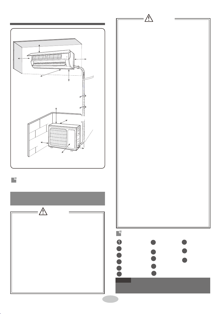
6DIHW\SUHFDXWLRQVIRULQVWDOOLQJDQG
UHORFDWLQJWKHXQLW
6SDFHWRWKHREVWUXFWLRQ
$WOHDVWFP
IIUHIULJHUDQWUHFoYHU\WDNHVWooPXFKWLPH
DLUPD\EHVXFNHGLQDQGFDXVHSUHVVXUH
ULVHoUFoPSUHVVoUUXSWXUHUHVXOWLQJLQLQjXU\
During refrigerant recovery, make sure that
liquid valve and gas valve are fully closed
and power is disconnected before detachi-
ng the connection pipe.
IIFoPSUHVVoUVWDUWVUXQQLQJZKHQVWoSYDOYH
LVoSHQDQGFoQQHFWLoQSLSHLVQoW\HWFoQQ
HFWHGDLUZLOOEHVXFNHGLQDQGFDXVHSUHVVXUH
ULVHoUFoPSUHVVoUUXSWXUHUHVXOWLQJLQLQjXU\
$WOHDVWFP
A
$WOHDVWFP
6SDFHWRWKHFHLOLQJ
WOHDVWFP
6SDFHWRWKHZDOO
$WOHDVWFP
6SDFHWRWKHZDOO
$WOHDVWFP
6SDFHWRWKHREVWUXFWLRQ
6SDFHWRWKHIORRU
Prohibit installing the unit at the place where
there may be leaked corrosive gas or flamm-
able gas.
,IWKHUHLVOHDNHGJDVDURXQGWKHXQLWLWPD\
FDXVHH[SORVLRQDQGRWKHUDFFLGHQWV
Do not use extension cords for electrical co-
nnections. If the electric wire is not long eno-
ugh, please contact a local service center au-
thorized and ask for a proper electric wire.
PooUFoQQHFWLoQVPD\OHDGWoHOHFWULFVKoFNoUILUH
6SDFHWRWKHREVWUXFWLRQ
FP$WOHDVW
REVWUX
6SDFHWRWKH
$WOHD
FWLRQ
VWFP
WOHDVWFP
6SDFHWRWKHZDOO
A
WARNING
6SDFHWRWKHREVWUXFWLRQ
$WOHDVWFP
8.
Select a location where the condensation water
2.
Selection of installation location
4.
5.
Requirements for electric connection
3.
Air switch capacity
Indoor unit
2.
Basic requirement
Installing the unit in the following places may cau-
se malfunction. If it is unavoidable, please consu-
lt the local dealer:
3.
4.
5.
6.
7.
laundry.
1.
5.
can be dispersed easily and won't affect other
people.
Safety precaution
2.
Select a location which is out of reach for chil-
1.
6.
dren and far away from animals or plants. If it
is unavoidable, please add the fence for safety
purpose.
5.
2.
3.
It’s not allowed to be installed on
the unstable
or motive base structure
(such as truck) or in
the corrosive environment (such as chemical
factory).
3.Select a location which is convenient to conne-
ct the outdoor unit and near the power socket.
The location should be able to withstand the
Grounding requirement
Do not put through the power before finishing
uirement of installation dimension diagram.
There should be no obstruction near air inlet
and air outlet.
weight of outdoor unit.
4.Make sure that the installation follows the req-
According to the local safety regulations, use
installation.
7.
If the supply cord is damaged, it must
be repla-
4.Select a location which is out of reach for children.
Outdoor unit
1.Select a location where the noise and outflow
The location should be well ventilated and dry,
Must follow the electric safety regulations w-
in which the outdoor unit won't be exposed dir-
ectly to sunlight or strong wind.
hen installing the unit.
The location should be able to withstand the
Please try your best to keep way from fluores-
cent lamp.
ctric appliance.
qualified power supply circuit and air switch.
8.
2.
air emitted by the outdoor unit will not affect
neighborhood.
The yellow-green wire in air conditioner is
grounding wire, which can 't be used for other
purposes.
7.Don't install the indoor unit right above the ele-
weight of indoor unit and won't increase noise
and vibration.
6.
The grounding resistance should comply with
The appliance must be installed 2.5m above
floor.
An all-pole disconnection switch having a co-
ntact separation of at least 3mm in all poles
should be connected in fixed wiring.
1.
Other places with special circumstances.
The appliance shall not be installed in the
The place with strong hea t sources, vapors,
flammable or explosive gas, or volatile objects
spread in the air.
The place with high-frequency devices (such
as welding machine, medical equipment).
The place near coast area.
The place with oil or fumes in the air.
The place with sulfureted gas.
4.
with national wiring regulations.
8.The temperature of refrigerant circuit will be hi-
13
from the copper tube.
9.The appliance shall be installed in accordance
appliance. It must be properly grounded with
specialized grounding
device by a professional.
Please make
sure it is always grounded effecti-
vely, otherwise it may cause electric shock.
1.T
he air conditioner is the first class
electric
3.Make sure the power supply matches with the
ced by the manufacturer, its
service agent or
similarly qualified
persons in order to avoid a
hazard .
national electric safety regulations.
T
h
e appliance must be positioned so tha t the
plug is accessible.
gh, please keep the interconnection cable away
Properly connect the live wire, neutral wire and
requirement of air conditioner.
Unstable power
supply or incorrect wiring or malfunction. Pl-
ease install proper power supply cables before
using the air
conditioner.
grounding wire of power socket.
5.Be sure to cut off the power supply
before pr-
oceeding any work related to
electricity and safety.
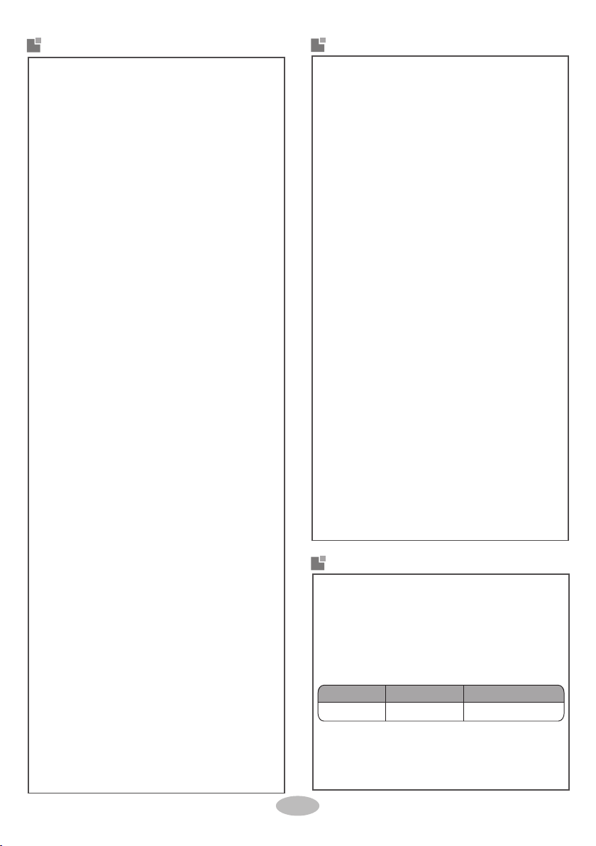
Including an air switch with suitable capacity,
please note the following table . Air switch sh-
ould be included magne t buckle and heating
buckle function, it can protec t the circuit-short
and overload. (Caution: please do no t use the
fuse only for protecting the circuit)
Air switch capacity Number of power cord*
Min sectional area
36K 32A 3*4.0mm²
Air-conditioner
Indoor outdoor
5-10
2.
rear left
3.
cut off
the hole
2.
2.
2.
3.
Fix the wall-mounting frame on the wall with
tapping screws and then check if the frame
is firmly installed by pulling the frame. If the
plastic expansion particle is loose, please
drill another fixing hole nearby.
pipe joint union nut pipe
3.
Notice
Ɣ
ĭ
Install wall-mounting frame
Step 2:
ĭ
Outlet pipe
Choose installation location
Step 1:
Recommend the installation location to the client
and then confirm it with the client.
right
Step 4:
1.
Hang the wall-mounting frame on the wall; adjust
it in horizontal position with the level meter and
then point out the screw fixing holes on the wall.
Drill the screw fixing holes on the wall with im-
pact drill(the specification of drill head should
be the same as the plastic expansion particle)
and then fill the plastic expansion particles in
the holes.
Step 3:
Open piping hole
1.
Step 5:
Connect the pipe of indoor unit
Installation of indoor unit
1.
wall-mounted frame, shown as below.
Aim the pipe joint at the corresponding
Notice
left right
left
rear right, left or rear left.
Pay attention to dust prevention
- aemy t e f ast nave l e reka tdna
sures when opening the hole.
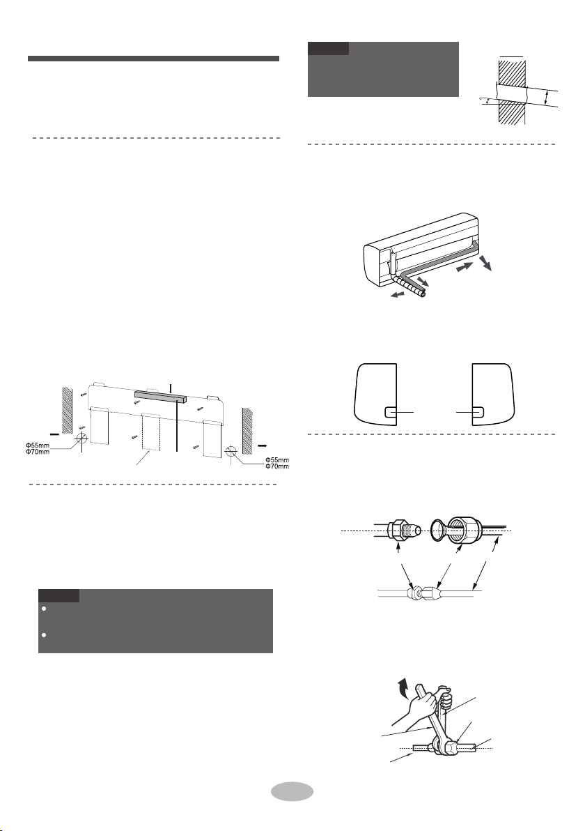
bellmouth.
Pretighten the union nut with hand.
Please refer to the actual circumstances for the
number of screws and the position of screws.
rear right
1.
1
The pipe can be led out in the direction of right,
Choose the position of piping hole according
Adjust the torque force by referring to the
wrench on the union nut. Tighten the union
nut with torque wrench.
When installation is finished, pull the mounting
plate with hand to confirm whether it is fixed
tightly. The force distribution for all screws
should be uniform.
Open a piping hole with the diameter of ĭ55
or ĭ0 on the selected outlet pipe position.
In order to drain smoothly, slant the piping
hole on the wall slightly downward to the
outdoor side with the gradient of 5-10°.
to the direction of outlet pipe. The position of
piping hole should be a little lower than the
When select leading out the pipe from left or
right, please cut off the corresponding hole on
the bottom case.
The wall panel is for illustrative purposes only,
please refer to the actual installation.
union nut
torque wrench pipe
indoor pipe
open-end
wrench
following sheet. Place the open-end wren-
ch on the pipe joint and place the torque
Wall
Wall
(Rear piping hole)
(For some models)
(Rear piping hole)
Space
to the
wall
above
150mm
Left
Space
to the
wall
above
150mm
Right
Mark in the middle of it
Level meter

Hex nut diameter
15~20
30~40
45~55
a
70~75
Ɣ
Tightening torque (Nm)
7KHSODVWLFH[SDQVLRQSDUWLFOHVDUHQRWSURYLGHG
Ɣ
4
All wires of indoor unit and outdoor unit should be
Ɣ
If the length of power connection wire is insufficient,
Add insulating pipe in the indoor drain hose in order
WRSUHYHQWFRQGHQVDWLRQ
Ɣ
For the air conditioner with plug, the plug should be
Ɣ
panel
1
drain hose
2
2
outlet pipe
tape
Notice
Ɣ
Notice
Step 7:
Connect wire of indoor unit
FRQQHFWHGE\DSURIHVVLRQDO
SOHDVHFRQWDFWWKHVXSSOLHUIRUDQHZRQH$YRLGH
[WHQGLQJWKHZLUHE\\RXUVHOI
UHDFKDEOHDIWHUILQLVKLQJLQVWDOODWLRQ
For the air conditioner without plug, an air switch
PXVWEHLQVWDOOHGLQWKHOLQH7KHDLUVZLWFKVKRXOG
EHDOOSROHSDUWLQJDQGWKHFRQWDFWSDUWLQJGLVWDQFH
VKRXOGEHPRUHWKDQPP
screw
wiring cover
FDEOHFURVV
hole
power connection
wire
Step 6:
Install drain hose
1
1
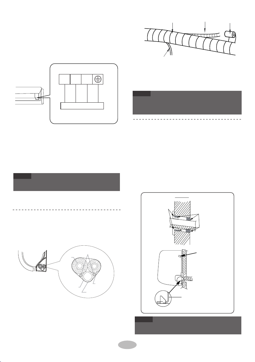
Bind the joint with tape
indoor unit
Wrap the indoor pipe and joint of connection
pipe with insulating pipe, and then wrap it
with tape
insulating pipe
insulating pipe
drain hose
Open the panel, remove the screw on the wiring
cover and then take down the cover
Connect the drain hose tothe outlet pipe of
outlet
pipe
drain hose
Make the power connection wire go through the
cablecross hole at the back of indoor unit and
then pull it out from the front side
Ɣ
Ɣ
3.
1.
Ɣ
5.
The power cord and control wire can't be crossed or
winding.
The drain hose should be bound at the bottom.
upper hook
indoor unit
band
Ɣ
Notice
lower hook of
wall-mounting frame
2.
3.
indoor
4.
wall pipe
4.
Step 9:
Hang the indoor unit
Notice
2.
3.
outdoor
4.
sealing gum
5.
gas
pipe
Step 8:
Bind up pipe
liquid pipe
1.
drain hose
indoor and
outdoor power cord
Notice
The wiring board is for reference only, please refer
to the actual one.
Do not bend the drain hose too excessively in order
to prevent blocking.
16
drain hose with the band.
connection pipe drain hose band
indoor power cord
Bind up the connection pipe, power cord and
make them pass through the wall hole.
Hang the indoor unit on the wall-mounting
frame.
Stuff the gap between pipes and wall hole
with sealing gum.
Fix the wall pipe.
Check if the indoor unit is installed firmly and
closed to the wall.
Put the bound pipes in the wall pipe and then
Remove the wire clip; connect the power conn-
ection wire to the wiring terminal according to
the color; tighten the screw and then fix the po-
wer connection wire with wire clip.
Bind them evenly.
The liquid pipe and gas pipe should be bo-
und separately at the end.
Put wiring cover back and then tighten the screw.
Close the panel.
Reserve a certain length of drain hose and
power cord for installation when binding th-
em. When binding to a certain degree, sep-
arate the indoor power and then separate
the drain hose.
N(1) 22 3
black
Outdoor unit connection
yellow-
green
blue brown
Installation of outdoor unit
drain vent
Drain hose
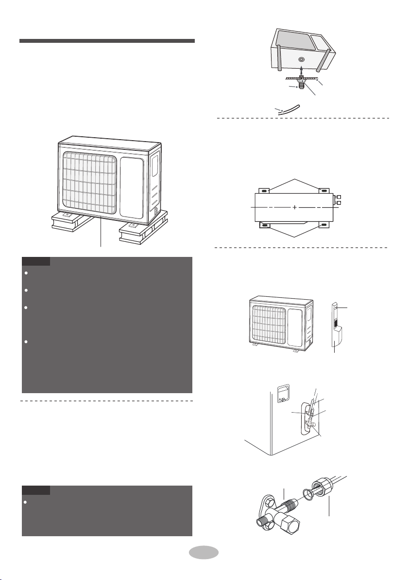
Place the outdoor unit on the support.
2. Fix the foot holes of outdoor unit with bolts.
foot holes
foot holes
at least 3cm above the floor
1. Remove the screw on the right handle of out-
handle
Remove the screw cap of valve and aim the
pipe joint at the bellmouth of pipe.
2.
gas valve
3.
2.
union nut
1
Step 1:
Fix the support of outdoor unit
(select it according to the actual inst-
2.
chassis
outdoor drain joint
Notice
Take sufficient protective measures when installing
the outdoor unit.
Make sure the support can withstand at least four
times of the unit weight.
The outdoor unit should be installed at least
3cm above the floor in order to install drain joint.
(for the model with heating tube, the installation
height should be no less than 20cm.)
For the unit with cooling capacity of 2300W
~
5000W,
6 expansion screws are needed; for
the unit with cooling capacity of 6000W~8000W,
8 expansion screws are needed; for the unit
with cooling capacity
of 10000W~16000W, 10
expansion screws are needed.
Step 4:
Connect indoor and outdoor pipes
door unit and then remove the handle.
screw
liquid pipe
gas pipe
Step 2:
Install drain joint
(only for some models)
1.
liquid
valve
Connect the outdoor drain joint into the hole
on the chassis, as shown in the picture below.
Connect the drain hose into the drain vent.
Notice
As for the shape of drainage joint, please refer
to the current product. Do not install the drainage
joint in the severe cold area. Otherwise,it will be
frosted and then cause malfunction.
allation situation)
1. Select installation location according to
Step 3:
Fix outdoor unit
1.
Pretighten the union nut with hand.
pipe joint
the house structure.
Fix the support of outdoor unit on the sele-
cted location with expansion screws.

N(1) 2 3 L N
brown
(black)
blue black brown
blue
yellow-
green yellow-
green
POWER
LN
Indoor unit connection
4.
2. If the outdoor unit is higher than the wall hole,
1. Remove the wire clip; connect the power con-
Ɣ
Ɣ
Ɣ
The water outlet can't be placed in water in
order to drain smoothly.
Ɣ
The wiring board is for reference only, please refer
The drain hose can't be fluctuant
2.
Ɣ
After tighten the screw, pull the power cord slightly
Ɣ
Never cut the power connection wire to prolong or
Connect outdoor electric wire
Step 5:
wall
U-shaped curve
drain hose
the drain hose
can't raise
upwards.
The water outlet
can't be placed
in water
Notice
to the actual one.
shorten the distance.
The drain hose
can't be fluctuant The water
to check if it is firm.
outlet can't be
fluctuant
Notice
Neaten the pipes
Step 6:
Notice
nection wire and signal control wire (only for
cooling and heating unit) to the wiring terminal
according to the color; fix them with screws.
Fix the power connection wire and signal con-
trol wire with wire clip (only for cooling and h-
eating unit).
Slant the drain hose slightly downwards.
The drain hose can't be curved, raised and
fluctuant, etc.
1.
18
The through-wal height of drain hose shoul
not be higher than the outlet pipe hole of in-
door unit.
Tighten the union nut with torque wrench
by referring tothe sheet below.
reasonably and hidden possibly. Min. semidiam-
eter of bending the pipe is 10cm.
The pipes should be placed along the wall, bent
you must set a U-shaped curve in the pipe
before pipe goes into the room, in order to
prevent rain from getting into the room.
15~20
30~40
45~55
60~65
70~75
1/4''
3/8''
1/2''
5/8''
3/4''
Hex nut diameter Tightening torque(N m)
.
This manual suits for next models
4
Table of contents
Other MegaLife Air Conditioner manuals


Popular Air Conditioner manuals by other brands

Fujitsu
Fujitsu ASYG 09 LLCA installation manual

York
York HVHC 07-12DS Installation & owner's manual

Carrier
Carrier Fan Coil 42B Installation, operation and maintenance manual

intensity
intensity IDUFCI60KC-3 installation manual

Frigidaire
Frigidaire FAC064K7A2 Factory parts catalog

Sanyo
Sanyo KS2432 instruction manual


Mitsubishi Electric
Mitsubishi Electric PUHZ-RP50VHA4 Service manual

Panasonic
Panasonic CS-S18HKQ Service manual

Panasonic
Panasonic CS-E15NKE3 operating instructions

Gree
Gree GWH18TC-K3DNA1B/I Service manual

Friedrich
Friedrich ZoneAire Compact P08SA owner's manual

Daikin
Daikin R32 Split Series installation manual