megapixel HELIOS User manual

HELIOS®
LED Processing Platform
User Guide
HELIOS v.21.08.0
2021-08-19

HELIOS LED Processing Platform - USER GUIDE i
1
System Components 1
Processor Overview 2
Processor Front Panel 3
Processor Rear Panel 3
Network Switch Overview 5
Display Tiles 6
2
System Planning 7
Overview 7
Video Input 7
Custom Input Bandwidth Calculations 7
Creating a Raster Map 8
Dual Input Cards 9
Data Distribution 9
3
Connections 11
Overview 11
System Latency 11
Processor Connections 11
4
Networking 13
Overview 13
IP Addressing 14
Table of Contents
Chapters

HELIOS LED Processing Platform - USER GUIDE ii
Table of Contents (Cont.)
Chapters
5
Conguration 16
Overview 16
Feedback 18
Creating Maps 22
Mapping Pane 23
Input Pane 27
Output Pane 37
Output Pane (Advanced) 41
GhostFrame Pane (Advanced) 49
Camera (Advanced) 54
Devices Pane 55
Processing Tab 55
Display Devices Tab 59
Health Pane 60
Alerts 60
Settings Pane 63
Security (Advanced) 68
Saved Congurations 72
Update Center 75
Software upgrade steps 76
Shortcuts 78
About 79
Preview Pane 80
Seams Pane 82
Adjustments Pane 85

HELIOS LED Processing Platform - USER GUIDE iii
Table of Contents (Cont.)
A
Maintenance & Accessories 86
General Maintenance 86
Processor Filter Maintenance 86
Processor Fuse Replacement 87
B
Unknown User / Password 88
Overview 88
Restoring to Factory Default 89
C
Troubleshooting Fiber 90
Overview 90
Incompatible SFP Alert 92
D
Low Level Noise Reduction 95
Overview 95
Low Level Noise Reduction Steps 96
E
Content to Panel Luminance Curves 98
F
Data Redundancy 101
Overview 101
Redundancy Settings 102
Stacking Settings 105
Devices Pane Link Icon 105
Upgrade Process 106
G
Technical Specications 107
Network Switch - Specications Table 107
Network Switch - Shipping Info. 107
HELIOS Processor - Specications Table 108
HELIOS Processor - Shipping Info. 109
HELIOS Processor Dimensions 109
HELIOS Processor - Input Capability Matrix 110
HELIOS Processor - Supported SDI Input Formats 111
HELIOS Processor - Output Port Capacity (Pixels) 111
Fiber Out / Data to Tiles 112
Network Ports 112
Thermal Sensor Alert Levels 113
Normal Voltage Ranges 113
Appendixes

HELIOS LED Processing Platform - USER GUIDE iv
Legal
Copyright © Megapixel Visual Reality®.
The Megapixel VR®logo is a trademark of H2VR HoldCo, Inc. Other trademarks and trade names may be used
in this document to refer to products by other entities. Megapixel VR claims no proprietary interest in
trademarks and trade names owned by others.
Information and specications in this document are subject to change without notice. Megapixel VR assumes
no responsibility or liability for any errors or inaccuracies that may appear in this manual.
Contact
+1 818 884 5488
http://megapixelvr.com
Warranty Information
Megapixel VR warrants the HELIOS® LED Processing Platform, hardware products, against defects in materials
and workmanship under normal use for a period of one (1) year from the date of retail purchase by the
original end-user purchaser.
Megapixel VR does not warrant that the operation of the product will be uninterrupted or error free.
Megapixel VR is not responsible for damage arising from failure to follow product or installation instructions.

HELIOS LED Processing Platform - USER GUIDE v
Safety Information
The symbols below are used throughout this manual to identify important safety information. Heed all
warnings and safety information.
This device contains Electrostatic Sensitive Devices. Wear anti-electrostatic gloves or bracelet
when handling the device.
This device passed test under the condition of being used with professional devices only. It may
cause frequency interference when used in a domestic environment.
Signal may become disconnected when electrostatic is induced externally.
Installation Environment
The HELIOS Processor is designed to be rack mounted in a central control room for xed installations or ight
cased for rental / temporary applications.
The unit has been qualied to operate in a dry environment within a temperature range of 10°C to 35°C (50°F
to 95°F).
NOTE: Never obstruct the airow to the side ventilation slots. The front lters need to be regularly
checked and cleaned.
Symbol Meaning
Warning, Danger, or Caution
Risk of injury to yourself or the product.
Risk of Electrical Shock
Risk of severe electrical shock.

HELIOS LED Processing Platform - USER GUIDE vi
WARNING: Below is a set of environmental conditions that must be met prior to installing
Megapixel VR products. The installation and/or use of products in these environments not
meeting these conditions may void all warranties.
▪Installation locations must be free of moisture.
▪Installation locations must be dust free.
▪All heavy and dirty site work must be complete. This includes re-working or
modications to walls, ceiling and oor.
▪All construction materials and debris must be removed, area swept, vacuum cleaned,
and the oor wet-mopped.
▪Building structure, roof, and walls are sealed and weather proofed. Roof successfully
tested for leaks.
▪Outside drainage system and oor drains checked and tested to protect the
equipment from ooding.
▪Floors sealed and cleaned.
▪All doors and windows installed and operational with weather seals.
▪All nal wall preparation complete including all taping, joint compound and re
sealant. Walls to be primed and nish painted.
▪Overhead re sprinkler or suppression system installed and pressure tested.
▪HVAC ducts blown free of debris. HVAC shall be operational/balanced and running
72 hours prior to equipment installation.

HELIOS LED Processing Platform - USER GUIDE vii
FCC Statement
This equipment has been tested and found to comply with the limits for a class A digital device, pursuant to
Part 15 of the FCC rules. These limits are designed to provide reasonable protection against harmful
interference when the equipment is operated in a commercial environment.
This equipment generates, uses, and can radiate radio frequency energy. If the equipment is not installed and
used as directed in the instruction manual, it may cause harmful interference to radio communications. It is
the responsibility of the user to correct any interference.
Carrying and Handling the Equipment
Before you handle the HELIOS LED Processing Platform equipment, disconnect all cables and cords. Do not
operate the HELIOS LED Processing Platform equipment in areas with signicant amounts of airborne dust or
smoke, or near a humidier. Tiny airborne particles can damage the equipment.
Liquid Exposure
Keep the HELIOS LED Processing Platform equipment away from all sources of liquid. Protect equipment from
dampness, humidity, or wet weather, such as rain, snow, and fog.
Power
Unplug the power cord (by pulling the connector, not the cord) and disconnect all other cables if any of the
following conditions exist:
▪The power cord or plug becomes frayed or otherwise damaged.
▪Liquid has spilled onto the equipment.
▪The equipment is exposed to rain or excess moisture or humidity.
▪The equipment has been dropped, and has been damaged.
▪You suspect that the equipment needs service or repair.
▪You want to clean the case (use only the recommended procedure, described later in this document).
IMPORTANT: The only way to completely turn off power is to unplug the power cord.
WARNING: The AC cord has a three-wire grounding connector. This connector ts only a
grounded AC outlet. If you are unable to insert the connector into an outlet because the outlet
isn’t grounded, contact a licensed electrician to replace the outlet with a properly grounded one.
Do not defeat the purpose of the grounding pin.

HELIOS LED Processing Platform - USER GUIDE viii
Repairing
The HELIOS LED Processing Platform equipment does not have any user-serviceable parts. Do not attempt to
replace or repair any components inside the equipment. If the equipment needs service, contact the
company that provided or installed the equipment. If you open the equipment or install items, you risk
damaging the equipment. Such damage isn’t covered by the limited warranty on the equipment.
Medical Device Interference
HELIOS LED Processing Platform equipment contains components that emit electromagnetic elds, which
may interfere with pacemakers, debrillators, or other medical devices. Maintain a safe distance of separation
between your medical device and equipment. Consult your physician and medical device manufacturer for
information specic to your medical device. If you suspect equipment is interfering with your pacemaker or
any other medical device, stop using the equipment.
Medical Conditions
If you have a medical condition that could be affected by using HELIOS Processing equipment (e.g., seizures,
blackouts), consult with your physician prior to using HELIOS LED Processing Platform equipment.
High-Consequence Activities
HELIOS LED Processing Platform equipment is not intended to be used where failure could lead to death,
injury, or severe environmental damage.
Explosive Atmospheres
Using HELIOS LED Processing Platform equipment in any area with a potentially explosive atmosphere (e.g.
where the air contains high levels of ammable chemicals, vapors, or particles (such as grain, dust, or metal
powders), may be hazardous. Obey all signs and instructions.
Using Connectors and Ports
Never force a connector into a port. When connecting a device, make sure the port is free of debris, that the
connector matches the port, and that you have oriented the connector correctly in relation to the port.
Storing the Equipment
If you are going to store the HELIOS LED Processing Platform equipment for an extended period of time,
keep it in a cool and dry location (ideally, 71° F or 22° C).

HELIOS LED Processing Platform - USER GUIDE ix
Cleaning the Equipment
When cleaning the outside of the HELIOS LED Processing Platform equipment and its components, rst shut
down the equipment, then unplug all cords and cables. Use canned air such as ‘Turbo Blast’ by ACL Staticide
Inc. or a clean, soft, lint-free cloth to wipe the equipment exterior. Avoid getting moisture in any openings. Do
not spray liquid on the equipment. Do not use sprays, solvents, abrasives, or cleaners.
Changes
Megapixel VR provides this manual ’as is’ without warranty of any kind, either expressed or implied, including
but not limited to the implied warranties or merchantability and tness for a particular purpose. Megapixel VR
may make improvements and/or changes to the product(s) and/or the program(s) described in this
publication at any time without notice.
This publication could contain technical inaccuracies or typographical errors. Changes are periodically made
to the information in this publication; these changes are incorporated in new editions of this publication.
Certications
5015417
Megapixel VR

HELIOS LED Processing Platform - USER GUIDE 1
1
System Components
The HELIOS LED Processing Platform was designed to support high density display products for use in pro A/V,
broadcast, and production applications. The HELIOS Processor is compatible with video sources that have up to 8K
resolution (i.e media servers, production network switchers, and broadcast cameras). The HELIOS system will
automatically integrate system components as they are connected or replaced.
The HELIOS system consists of a Processor unit and one or more network switches. The HELIOS Processor is designed to
be located near the video source. The HELIOS Processor ingests the source video and converts it into a ber signal. The
HELIOS Processor is also responsible for serving the web based user interface (web UI) that is the user interface of the
system. The network switches carry both the video signal and the communication signals to and from from panels. As
such, there is information passing in both directions on the HELIOS ber links that can be up to 10km in length.
Figure 1: HELIOS system diagram.
Modular
LED Display
Outputs per Network Switch
12 bit 425,000
Pixels / Port
10 bit 510,000
Bit Depth
9x
HELIOS
Sync
Network Switch
LAN
Control Port
DisplayPort
4K / 5K
(can scale to 8K)
SDI
4K / 8K / 16K x 2K
HDMI
4K
(can scale to 8K)
Outputs per HELIOS
12 bit 4,250,000
Pixels / Port
10 bit 5,100,000
Bit Depth
1Gb or 2.5Gb Copper Ethernet lengths up to 100m
10Gb Fiber links up to 10km
8x
Receiving SFP+
1Gb or 2.5 Gb Copper
Sending SFP+
Jump to the port capacity
table for more details.

HELIOS LED Processing Platform - USER GUIDE 2
Processor Overview
The HELIOS Processor is a one RU (1.75”) tall rack mount unit that can receive video in resolutions up to 8K and outputs
that video as a proprietary stream to compatible video panels (Figure 2).
The HELIOS Processor is capable of receiving HDMI, DisplayPort, and SDI signals. The HDMI and DisplayPort inputs are
designed to be modular. Alternate combinations of DisplayPort and HDMI inputs are supported (e.g. two DisplayPort, or
two HDMI). Contact your Megapixel VR representative for more details. SDI inputs are provided by four Megapixel VR
SFP+ units which can receive quad 12G SDI. The default 8K processor conguration consists of (1) x HDMI, (1) x
DisplayPort and (4) x SDI.
The system is congured remotely via a web UI running Chrome or Safari browsers. The input image can be scaled up or
down to suit LED panel congurations and also has all the common controls for brightness, gamma, color temperature,
etc.
Figure 2: HELIOS Processor.

HELIOS LED Processing Platform - USER GUIDE 3
Indicator Color Meaning
White System boot
Black No link (no cable)
Yellow Valid link, no video
Blue Valid link, valid video
Red Error detected in the last 1.25 sec
Green / Cyan / Magenta Training cycle
Processor Front Panel
Figure 3: HELIOS Processor front.
Conguration Interface - on the front of the HELIOS Processor is an LCD display and a turn/push knob interface.
Air Inlets - slots to the left and right of the LCD display are ltered vents for chassis airow.
Processor Rear Panel
Figure 4: HELIOS Processor rear.
1 - Control Port - On the left side is an Ethernet port. This port should be used to place the processor on the system
control LAN. A laptop may directly connect, or in larger systems a wireless router connects here.
2 - VFMC Video Inputs - The video inputs are modular. At the center of the unit is a removable plate that houses
removable VFMC input boards. The HELIOS system supports HDMI and DisplayPort cards in these slots. HELIOS units can
be congured with dual HDMI or dual DisplayPort cards.
2A - VFMC Video Input Indicators - Next to each video input connector is a small LED that indicates the status of each
VFMC input link.
HELIOS LED Processing Platform - USER GUIDE 4
3 - SFP+ Inputs - Four (4) SFP+ slots provide copper SDI inputs. Each input requires a Megapixel 12G SFP+ and supports
formats up to 12G SDI. See the Input Capability Matrix in Appendix G for details. Indicators on each SFP+ slot show link
status.
4 - SFP+ Outputs - HELIOS Standard units support up to eight Megapixel 10G ber SFP+ outputs for data transmission to
the display. Likewise, HELIOS Junior units support up to eight Megapixel 1G copper SFP outputs. Indicators on each SFP+
slot show link status.
5 - External Sync - The BNC connector to the right of the ber outputs allows the HELIOS Processor to receive genlock
timing signals. An external sync is required when using multiple processors for data redundancy.
Indicator Color Meaning
Green Link to switch
Blue Connected to tiles
Indicator Color Meaning
Green Receiving a carrier signal
Blue Valid frame detected

HELIOS LED Processing Platform - USER GUIDE 5
Network Switch Overview
The HELIOS system leverages network switches, like the GSM4210P, for data distribution to the tiles. The network switch
connects to the HELIOS processor via 10Gb ber SFP+ uplink and has eight 1 / 2.5Gb copper Ethernet ports that serve as
outputs to the display. Systems may have up to eight switches per HELIOS and are typically co-located with the display. All
user controllable functions of the network switch are accessed via the HELIOS web UI.
Input - 10Gb ber SFP+ input, receives display data from HELIOS processor.
Display Outputs - 1 / 2.5Gb copper Ethernet ports, transmits video and control data to and from connected panels.
Power - IEC C14 A/C power connector. The network switch will boot as soon as power is supplied.
Figure 5: GSM4210P network switch I/O.
Input from HELIOSSerial port
OOB Display Outputs
Power Inlet

Display Tiles
Display Tiles are the light emissive video panels containing receiver cards. They are at the end of the video signal chain.
Display tiles come in many shapes and sizes from a variety of vendors. Below are some common characteristics.
Input - Copper Ethernet input receives display data from a network switch or from another tile ahead of it in the chain.
Output - Copper Ethernet outputs send video and control data to the tiles downstream.
Power - Power must be supplied to each tile. Power connectors differ for each tile type.
Status Indicators - On the rear of each display tile is a multi color indicator button, the exact location varies by tile type.
The table below details the buttons functions and the meaning of each indicator color.
Figure 6: Status Indicator
HELIOS LED Processing Platform - USER GUIDE 6
Front
Status Indicator
Indicator Color Meaning
White Booting
Cyan Booted into safe mode
Green Ready (No network connection)
Blue Single Flash No HELIOS connection (1 tile link active)
Blue Double Flash No HELIOS connection (2 tile links active)
Blue Solid Connected to HELIOS (Normal operation)
Yellow Internal Pattern (press and hold center button 4 seconds to enter and
leave this mode). Press and release to advance to the next pattern.
Red Flash once every 10 sec to indicate a system error.

HELIOS LED Processing Platform - USER GUIDE 7
2
System Planning
Overview
This chapter covers the activities and considerations that need to be made prior to ordering equipment. If assistance is
needed with any of the items below, Megapixel VR is available to assist. Please contact a sales associate.
Ensure compatibility of the display product being considered with the HELIOS system. The HELIOS system can be used
with a continuously expanding list of products. Please see the HELIOS software release notes available on the Megapixel
VR website for current product compatibility https://megapixelvr.com/support/helios.
Video Input
Pixel dimensions -The number of pixels in the nal display is a major factor in selecting a video input type. If at all
possible it is best to rst settle on a quantity of pixels that need to be driven before selecting an input
format.
Input formats - Select an input format that can support the required pixels. HELIOS accepts three input formats:
• HDMI
• DisplayPort
• SDI
A detailed Input Capability Matrix can be found in Appendix G.
Custom Input Bandwidth Calculations
HDMI and DisplayPort can support custom input resolutions and frame rates, it is important to conrm that the intended
resolution/frame rate will t within the bandwidth limits. Bandwidth limit conrmation is less of a concern when using SDI
since SDI is a controlled standard with xed formats.
The following formula is used make the maximum bandwidth calculation:
(Pixel Width * Pixel Height) * Frame Rate * (Bits/Pixel * 3) = Maximum Bandwidth
As an example, the largest standard aspect ratio DisplayPort signal HELIOS supports is 5K (5120x2880) @60 Hz 8bit. Bits
per pixel is multiplied by 3 since each pixel gets a red, green, and blue signal.
(5120 * 2880) * 60 * (8 * 3) = 21,233,664,000 (21.2G)
NOTE: Extreme cases of very tall and narrow displays may not work due to overhead timing constraints of blanking time.
Input Frequency Maximum Pixel
Dimensions
Maximum
Bandwidth
HDMI 60Hz 4096 x 2160 14.4G
DisplayPort 60Hs 5120 x 2880 22.6G

HELIOS LED Processing Platform - USER GUIDE 8
Creating a Raster Map
It is a good idea to create a raster map drawing to document which portion of the video signal serves which portion of the
display. The example below contains two separate displays (blue tiles). In this case, the pixel dimensions of both displays
will t on a 6K raster. The larger 8K and DCI 8K rasters are shown for reference.
Figure 7: Example raster map
Sometimes, the ‘as built’ shape of the system does not t any horizontal or vertical rasters, but the total number of pixels
can. This is the case with a long ribbon display. Rasters can be rearranged, (within certain limitations) on the front end if
necessary. In the end, the picture to be transmitted to a display needs to t inside of the pixel dimensions of one of the
three supported input signals (HDMI, DisplayPort, or SDI). For long strip style displays this means that the incoming picture
needs to be divided into segments, these are labeled with capital letters in the example below (A, B, C etc.). Content can
be created in segments or the segmentation can be accomplished with media processing equipment prior to the HELIOS
Processor. The example below shows a dual HDMI input conguration (see the following section on dual input cards).
Figure 8: Long ribbon display map example
3840 x 2160 @60Hz
Section 1
3840 x 2160 @60Hz
3840 x 540
16 x 4 Panels
2880 x 540
12 x 4 Panels
3840 x 540
16 x 4 Panels
3840 x 540
16 x 4 Panels
3840 x 540
16 x 4 Panels
3840 x 540
16 x 4 Panels
3840 x 540
16 x 4 Panels
3840 x 540
16 x 4 Panels
A B
C D
E F
G H
6k
6016 x 3384
8k
7680 x 4320
DCI 8k
8192 x 4320
1.5mm Display 12x12 1.5mm Display 5 x 14

HELIOS LED Processing Platform - USER GUIDE 9
Dual Input Cards
If the total number of pixels will not t any single input raster, the system can be fed video from multiple input cards. A
HELIOS Processor with the necessary hardware (dual DisplayPort or dual HDMI cards) can receive dual video signals of the
same type of signal. When HELIOS is outtted with two of the same card type (DisplayPort or HDMI) it will stitch the two
rasters together into one continuous output to tiles. Please see the Input Setup section in Chapter 5 for more information
on conguring this mode.
Figure 9: Dual DisplayPort Input Card Conguration
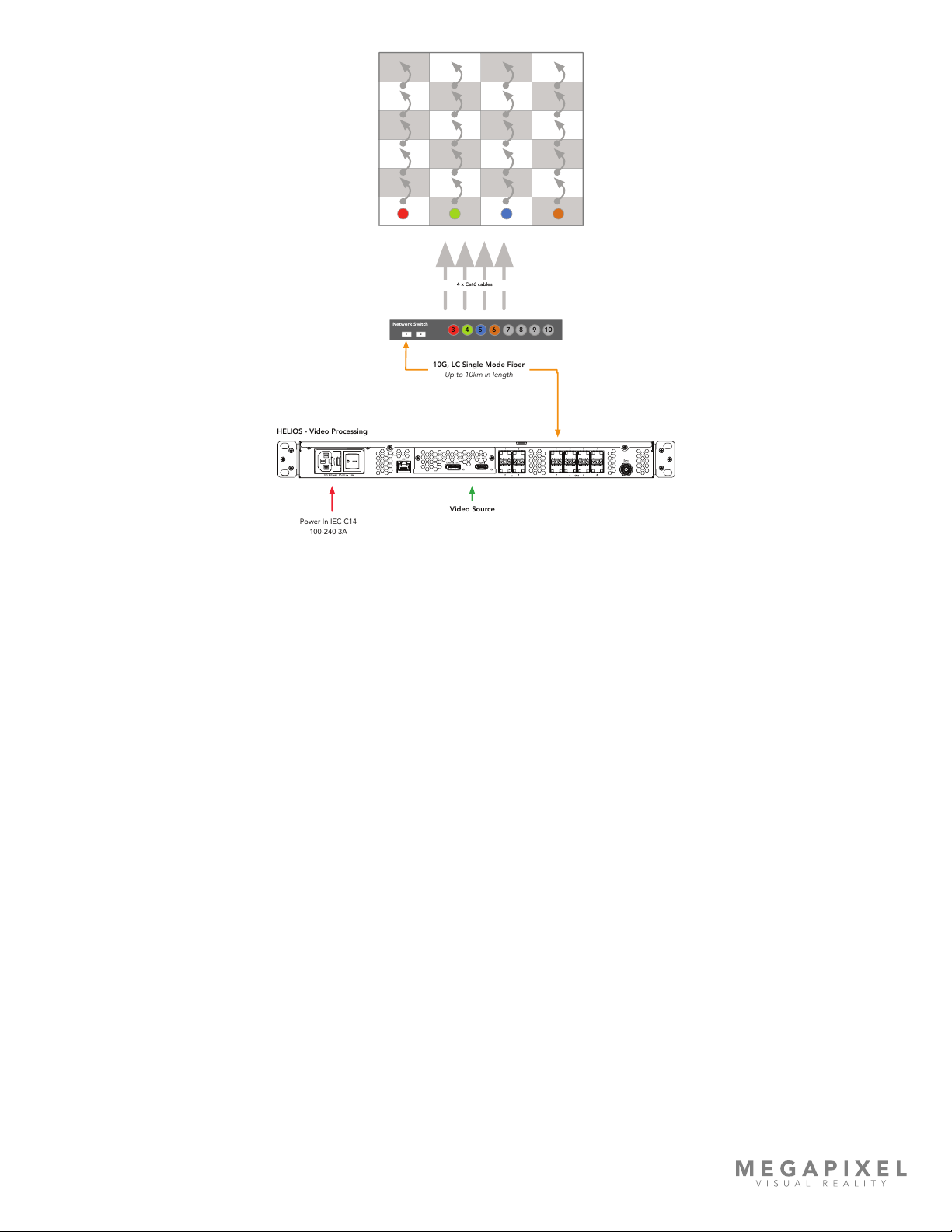
Data Distribution
At this point it can be helpful to draw out the data topology (gure 10). Decide if the display will be cabled vertically or
horizontally. Calculate the number of network switches it will take to distribute data to the display. In the system example
below we use a tile with the pixel dimensions 480 x 270 (tiles are 129,600 pixels). From the Output Port Capacity table in
Appendix G we see that a 1Gbps switch port running a color bit depth of 12 at 30Hz can support up to 850,000 pixels
(850,000 / 129,600 = 6.5). If bit depth and frequency requirements change, the system bandwidth must be recalculated.
This tells us we can safely put 6 of these tiles on a 1Gb link.
Figure 10: Output capacity table
Check to make sure the entire data load on each network switch is within the limits of 10Gb ber. In this case, we are
using a color bit depth of 12 at 30Hz. So, the 10Gb link can support 8,500,000 pixels / 129,000 = 65.58 tiles per 10Gb link.
With only 24 tiles in the example system we know we are well within the limits. Always aim to distribute data evenly, spread
the load across switches and switch ports as evenly as possible.
HELIOS LED Processing Platform - USER GUIDE 10
Figure 11: Example data distribution drawing
Cable infrastructure - Check that the types of cables chosen are appropriate for the display type and for the location. This
is the point at which site specic considerations need to be made.
Important items to check:
• Where will the video source device reside?
• Is the HELIOS Processor close enough to the video source device to be within the specication of the video protocol
being used (e.g. HDMI, DisplayPort, and SDI).
• Is there power for the HELIOS Processor at the location?
• Has power for the network switches been allotted?
• What is the distance from the HELIOS Processor to the network switches at the display? Is this under the 10km
specication of the single-mode ber?
• What is the distance from the network switch to the rst panel in the display that each drives? Is this under the 100
meter limit of the copper Ethernet signal?
Network Switch
124 5 6 7 83 9 10
Video Source
Power In IEC C14
100-240 3A
HELIOS - Video Processing
10G, LC Single Mode Fiber
Up to 10km in length
4 x Cat6 cables
Other manuals for HELIOS
2
This manual suits for next models
1
Table of contents


