Clear-Com CCI-22 User manual

DUAL PARTY-LINE INTERACE
INSTRUCTION MANUAL
CCI-22

CCI-22 Dual Party-Line Interface Instruction Manual
©1997, 2005 Vitec Group Communications, Inc.
All Rights Reserved
Part Number 810307 Rev. A
Vitec Group Communications, Inc.
4065 Hollis Street
Emeryville, CA 94608-3505
U.S.A
Clear-Com is a registered trademark of Vitec Group Communications, Inc.
The Clear-Com Logo is a registered trademark of Vitec Group Communications, Inc.
Eclipse is a registered trademark of Vitec Group Communications, Inc.
Windows is a registered trademark of Microsoft Corp.

CCI-22 DUAL PARTY-LINE INTERFACE iii
CONTENTS
IMPORTANT SAFETY INSTRUCTIONS v-vi
OPERATION 1-1
Introduction . . . . . . . . . . . . . . . . . . . . . . . . . . . . . . . . . . . . . . . . . . . . . . . . . 1-1
Operation . . . . . . . . . . . . . . . . . . . . . . . . . . . . . . . . . . . . . . . . . . . . . . . . . . . 1-2
INSTALLATION 2-1
Introduction . . . . . . . . . . . . . . . . . . . . . . . . . . . . . . . . . . . . . . . . . . . . . . . . . 2-1
Installation In Interface Frame . . . . . . . . . . . . . . . . . . . . . . . . . . . . . . . . . . . 2-1
Wiring . . . . . . . . . . . . . . . . . . . . . . . . . . . . . . . . . . . . . . . . . . . . . . . . . . . . . 2-2
Adjustments . . . . . . . . . . . . . . . . . . . . . . . . . . . . . . . . . . . . . . . . . . . . . . . . . 2-9
Configuration . . . . . . . . . . . . . . . . . . . . . . . . . . . . . . . . . . . . . . . . . . . . . . . 2-10
MAINTENANCE 3-1
Introduction . . . . . . . . . . . . . . . . . . . . . . . . . . . . . . . . . . . . . . . . . . . . . . . . . 3-1
Diagrams . . . . . . . . . . . . . . . . . . . . . . . . . . . . . . . . . . . . . . . . . . . . . . . . . . . 3-6
SPECIFICATIONS 4-1
VITEC GROUP COMMUNICATIONS WARRANTY 5-1
Factory Service . . . . . . . . . . . . . . . . . . . . . . . . . . . . . . . . . . . . . . . . . . . . . . . 5-1
Warranty Repair . . . . . . . . . . . . . . . . . . . . . . . . . . . . . . . . . . . . . . . . . . . . . . 5-2
Non-Warranty Repair . . . . . . . . . . . . . . . . . . . . . . . . . . . . . . . . . . . . . . . . . . 5-2

CCI-22 DUAL PARTY-LINE INTERFACE
iv

CCI-22 DUAL PARTY-LINE INTERFACE v
IMPORTANT SAFETY INSTRUCTIONS
For your safety, it is important to read and follow these instructions before
operating a CCI-22 dual party-line interface :
(1) WARNING: To reduce the risk of fire or electric shock, do not expose a
CCI-22 to rain or moisture. Do not operate a CCI-22 near water, or place
objects containing liquid on it. Do not expose a CCI-22 to splashing or dripping
water.
(2) For proper ventilation, make sure ventilation openings are not blocked.
Install the CCI-22 according to the directions in the Installation Chapter of this
manual.
(3) Do not install a CCI-22 near a heat source such as a radiator, heat register,
stove, or other apparatus (including amplifiers) that produces heat. Do not place
naked flame sources such as candles on or near a CCI-22.
(4) Do not defeat the safety purpose of the polarized or grounding-type plug. A
polarized plug has two blades, with one blade wider than the other. A
grounding-type plug has two blades and a third grounding prong. The wide
blade or the third prong is provided for your safety. If the provided plug does not
fit into your outlet, consult an electrician for replacement of the obsolete outlet.
(5) Protect the power plug from being walked on or pinched particularly at
plugs, convenience receptacles, and the point where they exit from the i-station’s
chassis.
(6) Only use attachments/accessories specified by Clear-Com Communication
Systems.
(7) Unplug the CCI-22 during lightning storms or when unused for long periods
of time.
(8) Refer all servicing to qualified service personnel. Servicing is required when:
•The CCI-22 has been damaged in any way, such as when a power-supply
cord or plug is damaged.
•Liquid has been spilled or objects have fallen into the CCI-22.
•The CCI-22 has been exposed to rain or moisture.
•The CCI-22 does not operate normally.
•The CCI-22 has been dropped.
Please familiarize yourself with the safety symbols in Figure 1. When you see
these symbols on a CCI-22, they warn you of the potential danger of electric
shock if the product is used improperly. They also refer you to important
operating and maintenance instructions in the manual.
Please read and follow these
instructions before operating
a CCI-22 dual party-line
interface.

CCI-22 DUAL PARTY-LINE INTERFACE
vi
Figure 1: Safety Symbols
CAUTION
RISK OF ELECTRIC SHOCK
DO NOT OPEN
This symbol alerts you to the presence of uninsulated dangerous
voltage within the product's enclosure that might be of sufficient
magnitude to constitute a risk of electric shock. Do not open
the product's case.
This symbol informs you that important operating and main-
tenance instructions are included in the literature accompanying
this product.

ICS-1008/1016 INTERCOM STATION 1-1
OPERATION
INTRODUCTION
This chapter describes how to use the CCI-22 dual party-line interface. You can
use this chapter once the Eclipse matrix system has been correctly installed and
configured with the Eclipse Configuration System, and when the CCI-22's
internal jumpers have been set. For information on configuring the CCI-22 refer
to Chapter 2, “Installation.”
DESCRIPTION
Each CCI-22 dual party-line interface can connect two independent external
2-wire party-line intercom systems to the Eclipse matrix. It will support
Clear-Com and many other party-line formats.
The CCI-22 fully supports call signals between the matrix and a Clear-Com
party-line; call signals between the matrix and other party-line types may not be
fully supported. All call signal paths are optically isolated. All audio paths are
transformer isolated, eliminating noise induced by ground loops in the party-line
systems. "Send" and "receive" level controls are included on the front panel. The
CCI-22 features sophisticated "sidetone nulling" circuitry.
The CCI-22 occupies one slot in an IMF-3 or IMF-102 interface module frame.
Connections to the matrix are via 8-pin RJ-45 connectors on the rear panel.
Connections to external party-lines are via 9-pin connectors on the rear panel.
The CCI-22's party-line circuits do not receive power from the matrix, but must
be connected to an externally powered party-line.
More than one CCI-22 interface ports may be preset to one Eclipse system
party-line label to create a single unified party-line. However, the nature of
2-wire to 4-wire hybrid conversions may limit the maximum number of external
2-wire party-lines that can be combined. Call signals to any one of the CCI-22
channels will reach destinations in the other CCI-22 channels in addition to the
destination ports within the matrix.
When a CCI-22 interface port receives a call signal from a Clear-Com party-line,
it will be sent to all ports in the matrix which have “listens” activated to the
party-line at the time of the call signal. In addition, call signals can be
programmed to signal specific stations (see the Configuration section of the
Installation chapter).
OPERATION
In normal use, the CCI-22 interface does not require operator interaction. The
front panel features a set of level controls and a power indicator LED. The front
panel also includes a set of three "sidetone null" adjustment controls. The null
adjustment controls are discussed in “Installation,” Chapter 2.
1

ICS-1008/1016 INTERCOM STATION
1-2
LEVEL CONTROLS
The Send level controls affect the level of the audio signals from the matrix to the
external party-line, and the Recv ("receive") control affects the level of the audio
from the party-line into the matrix.
The Send and Receive controls have a range of ± 13 dB. They are normally set at
the center position when used with Clear-Com party-line equipment.
POWER LED
The green Power LED lights when DC power is supplied to the interface. The
interface is powered by the party-line it is connected to.
Sidetone Null Adjustment
Normally this adjustment is made once during installation. If additional
adjustment is required use the following procedure.
"Sidetone" is the sound of the operator's own voice in his or her headset. In
interfaces, it is necessary to "null" (minimize) the sidetone when an external
party-line is placed in the matrix environment. Ideally, there should be no
portion of the Talk signal in the Listen signal. The side-tone nulling procedure
for each channel of the CCI-22 is described here.
The CCI-22 includes built-in nulling circuitry, including a test tone generator
and an accessory earphone. The earphone plugs into a 1/8-inch phone jack on
the front panel. When the earphone is plugged in, it automatically switches on a
test tone, and monitors the output of the null circuit.
Separate "R" (Resistance), "L" (Inductance), and "C" (Capacitance) controls
compensate for each component of the line's impedance, providing the best null
possible.
The null circuit is effective on line lengths between zero and 4000 feet with
impedances in the range of 120 to 350 ohms, and can reduce local audio in the
received signal by more than 30 dB over the frequency range of 200 Hz to 8 kHz.
To null one channel of the CCI-22:
1. Connect the external party-line devices to the CCI-22 channel.
2. Plug the accessory earphone into the front panel jack labeled "Test". This will
disconnect the interface from the matrix and enable the test oscillator. The
oscillator produces a square wave with both low and high harmonics, allowing
you to test all frequencies. The test tone pulses approximately every
half-second.
3. While listening to the test tone in the earphone, adjust the "R" control until
the tone is at a minimum.
4. Repeat Step 3 with the "L" and "C" controls. Because these controls interact
with each other, you will need to repeat steps 3 and 4 several times before you
will have minimized the test tone. Continue adjustment until the tone is
virtually inaudible. If an almost complete null cannot be obtained, it is likely
that something is wrong either with the wiring in the external party-line, or
with one of the other devices attached to the external party-line. Steps 5
through 9 are troubleshooting hints.

ICS-1008/1016 INTERCOM STATION 1-3
5. If the "R" control is turned fully counter-clockwise, the line has either more
than one termination, or an excessive resistive load.
6. If the "R" control is fully clockwise, then the line has no termination.
7. The "L" control compensates for the low-frequency inductive and capacitive
elements of the external party-line. If the "L" control is fully turned in either
direction, it is likely that there is a problem in the external party-line. When a
Clear-Com party-line is connected, the "L" control should be just to one side
of its mid-pot position.
8. The "C" control compensates for cable capacitance; the setting depends on the
length of the line. If the "C" control is fully counter-clockwise, this indicates a
very short line (under ten feet); this is a valid setting for a short line.
9. If the "C" control is fully clockwise, this indicates an excessively long line (over
4,000 feet).

ICS-1008/1016 INTERCOM STATION
1-4

CCI-22 Dual Party-Line Interface 2-1
INSTALLATION
INTRODUCTION
This chapter describes the installation of the CCI-22 dual party-line interface,
including setting internal jumpers, wiring to external devices, and setting
front-panel controls and indicators.
INSTALLATION IN INTERFACE FRAME
To install the CCI-22 interface module in the IMF-3 or IMF-102 interface
frame:
1. Select a slot in which to install the interface.
2. Remove the blank plate covering the slot.
3. Set any Party-Line Termination Jumpers as necessary.
4. Slide the CCI-22 in the slot and ensure that the card is fully seated.
5. Tighten the CCI-22’s front-panel mounting screws.
TERMINATION OF PARTY-LINES
A “Clear-Com termination network” (also known simply as a “termination”) is a
Resistor-Capacitor (RC) circuit that must be connected between the Audio and
Ground lines of any Clear-Com party-line. To ensure correct operation of the
external party-line, only one termination can be installed on any given party-line.
A party-line termination is normally provided by the component powering the
party-line. Although the CCI-22 is not designed to supply power to an external
party-line system, each channel of the CCI-22 features a Clear-Com termination
circuit that can be connected to the party-line by installing a jumper. This
termination network is not normally connected, and should only be connected
in the rare case that the external party-line does not include a termination circuit.
An example of the use of these termination networks is in Figure 7on page 2-5.
If a party-line has more than one termination circuit, it will not null correctly
(see “Sidetone Null Adjustment” on page 2-8). The most common symptom of
this is when the line does not null, even though the “R” null control has been
turned all the way counter-clockwise. If this happens, check all components
connected to the party-line that are capable of providing a termination to be sure
that only one termination is connected to the party-line.
The two termination circuits on the CCI-22 connect to the channel A and B
party-lines; they are enabled and disabled by the jumpers at JP100 (which
controls the termination circuit for channel A) and JP200 (which controls the
termination for channel B). JP100 and JP200 are located near the center of the
CCI-22 main circuit board, and are shown as a detail in the assembly drawing for
the CCI-22 main circuit board in the Maintenance Chapter. When either
2
CCI-22 Dual Party-Line Interface
2-2
jumper is next to the label “B,” its termination is disabled; moving the jumper
next to the label “A” enables the termination.
WIRING
The CCI-22 interfaces are connected to the matrix frame through the two RJ-45
connectors on the IMF-3 or IMF-102 rear-panel assembly to which CCI-22 is
connected. For connection to a matrix frame refer to the “Installation in Interface
Frame” on page 2-1. For internal jumper settings and adjustments refer to
“Adjustments” on page 2-8.
The “user” side of the CCI-22 for each channel is on a pair of DB-9M
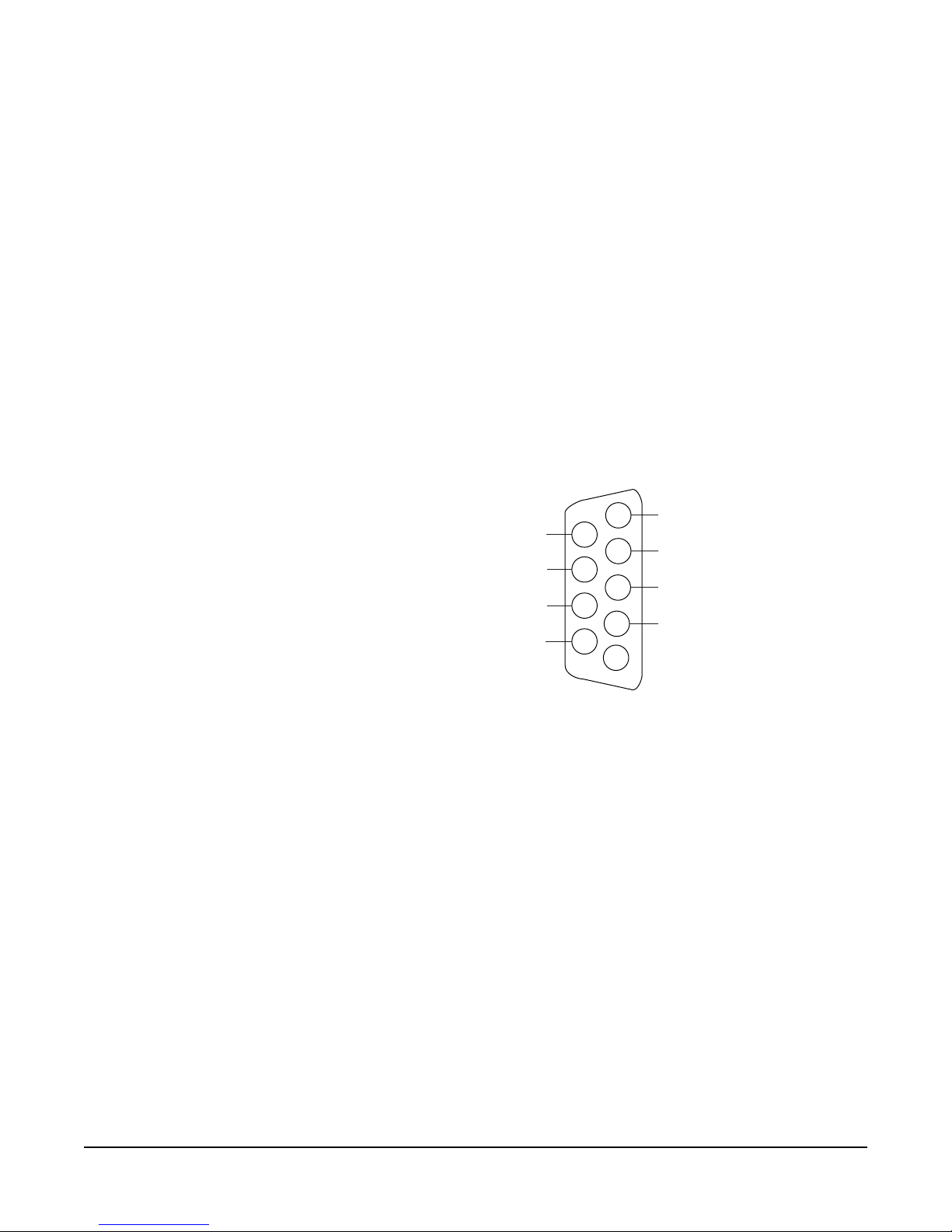
connectors on the rear of the interface frame. Figure 2 shows the pinout of either
one of these connectors. Both DB-9Ms are paralleled such that both party-line
channels are available on each connector. It is possible to wire one DB-9
connector as channel #1, the second DB-9M as channel #2, or bring both
channels out either DB connector separately or create a TW type party-line
connection.
Figure 2: Pinout of the DB-9M Interface I/O Connectors
CLEAR-COM PARTY LINES GENERAL DISCUSSION
Stations on Clear-Com party-lines are connected with two-conductor shielded
microphone cable. One conductor carries the DC power (28 to 30 V), while the
other carries the duplex two-way intercom audio signal and DC “Call Light”
signaling. The shield acts as common ground for both the power and signal.
Power to the CCI-22 interface channels must be provided by the external
party-line. The power connection for each channel is the “+30 VDC Power” pin
on the appropriate DB-9M Interface I/O connector located on the rear-panel
assembly. The CCI-22 channel is essentially just another “beltpack” on the
party-line.
The power pin has a DC filtering circuitry to provide a high impedance for the
audio so the power can be received from a “powered line or TW line” as is
common with RTS systems. For TW operation tie the AUDIO and POWER
pins together.
Each party-line channel requires exactly one termination circuit. The
termination circuit is usually built into the system component providing the
6
7
8
9
1
2
3
4
5
Channel 2 Channel 1
CC/RTS
Ground
+30 VDC Power
Audio
CC/RTS
Ground
+30 VDC Power
Audio
CCI-22 Dual Party-Line Interface 2-3
party-line’s power. Connecting more than one termination circuit to a party-line
will impair the sidetone null and degrade the line’s audio quality.
When a CCI-22 party-line channel is connected to a Clear-Com party-line, the
Clear-Com/Other Select pin must be left floating. Grounding this pin selects the
RTS mode, which is incompatible with Clear-Com party-lines.
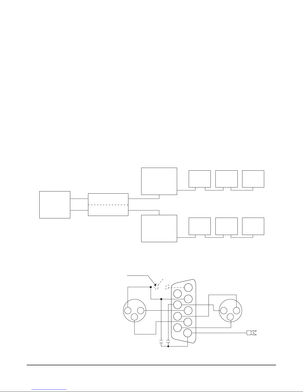
TWO SEPARATE PARTY LINES
The diagram in Figure 3 shows the CCI-22’s two channels connecting two
independent external party lines to the matrix. Each external party line provides
its own power and termination. The wiring diagrams in Figure 4 and Figure 5
show an external switch on the Clear-Com/Other Select pin; this switch allows
the CCI-22 channel to be used on either Clear-Com or RTS party-lines.
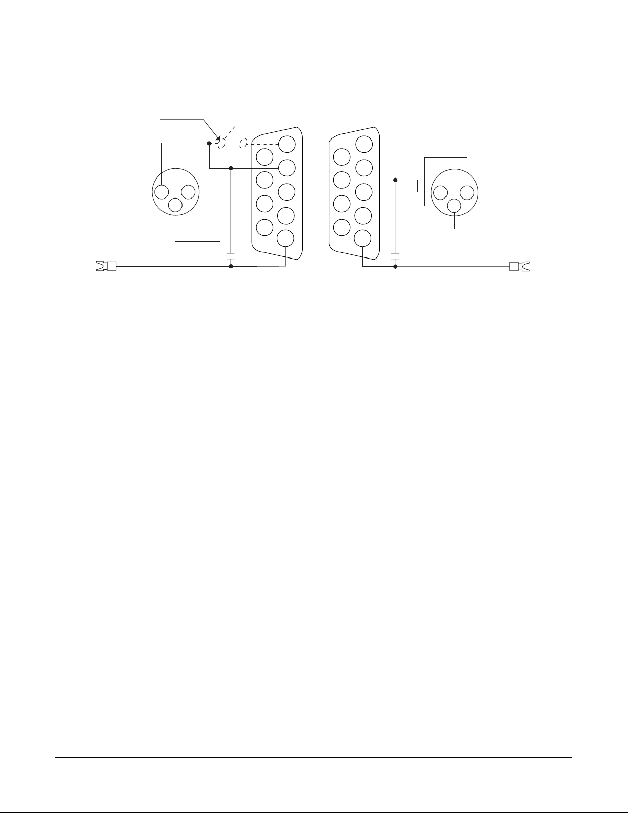
In the wiring diagram in Figure 4, all connections to the CCI-22 are made using
only one of the CCI-22’s two parallel DB-9M connectors. The wiring diagram in
Figure 5 shows the same connections as Figure 4, except that each DB-9M
connector is wired separately. Use the wiring method that is most convenient for
the installation.
Figure 3: Two External Party-Lines Connected to the CCI-22
Figure 4: One DB-9 Connected to the CCI-22
CCI-22
Matrix
Clear-Com
Power Supply
w/ Termination
Beltpack Beltpack Beltpack
Clear-Com
Power Supply
w/ Termination
Beltpack Beltpack Beltpack
6
7
8
9
1
2
3
4
5
2
3
12
3
1
Optional Clear-Com/RTS
External Switch
Two 0.01 uF
7-in. 18 gauge wire
Spade Lug to
Chassis Ground
on IMF-3
XLR XLR
Channel 1 Channel 2
CCI-22 Dual Party-Line Interface
2-4
Figure 5: Two Separate DB-9 Connections to the CCI-22
MULTIPLE CLEAR-COM BELTPACK CHANNELS FROM ONE POWER SUPPLY
A single two-output power supply can provide power for more than two CCI-22
party-line channels. In this case the power supply provides power for each
party-line, but each CCI-22 channel provides the termination for each
party-line. Many Clear-Com power supplies have a switch to enable or disable
the termination circuits from each of its outputs. If using such a supply:
1. Disable the terminations by using the switch.
2. Connect the PS-22 output to all of the CCI-22 channels to be powered using
the standard three connections in the XLR connector.
3. Set the termination jumper for each CCI-22 channel to position “A”
(termination connected) as described in “Termination of Party-Lines.”
If the power supply does not have a termination-disconnect switch, wire the
system as shown in Figure 6. In this configuration, only the power supply
channel’s power and ground lines are connected to the party-line.
Note: Do not connect the power supply output’s terminated audio line to the party
line.
Do not let the power supply output’s current rating exceed the total current
drawn by the devices powered.
6
7
8
9
1
2
3
4
5
6
7
8
9
1
2
3
4
5
2
3
12
3
1
Optional Clear-Com/RTS
External Switch
0.01 uF 0.01 uF
7-in. 18 gauge wire
7-in. 18 gauge wire
Spade Lug to
Chassis Ground
on IMF-3
Spade Lug to
Chassis Ground
on IMF-3
XLRXLR
Channel 1 Channel 2
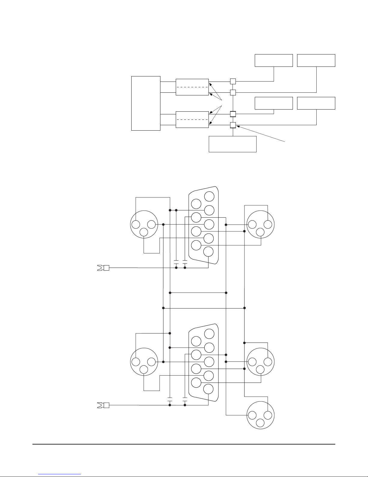
CCI-22 Dual Party-Line Interface 2-5
Figure 6: Diagram of One Power Supply with Four CCI-22 Terminations
Figure 7: Wiring of One Power Supply for More than Two Party-Line Channels
Matrix
Beltpack #1 Beltpack #2
Beltpack #3 Beltpack #4
Clear-Com
Power Supply
CCI-22
CCI-22
Set Terminations in CCI-22
Power and Ground
Connections Only
6
7
8
9
1
2
3
4
5
2
3
12
3
1
Two 0.01
uF
7-in. 18 gauge wire
Spade Lug to
Chassis Ground
on IMF-3
Beltpack #1
XLR
Beltpack #2
XLR
6
7
8
9
1
2
3
4
5
2
3
12
3
1
2
3
1
Two 0.01
uF
7-in. 18 gauge wire
Spade Lug to
Chassis Ground
on IMF-3
Beltpack #3
XLR
Beltpack #4
XLR
To Clear-Com
PS-22
Power Supply
DB-9F On
First CCI-22
DB-9F On
Second CCI-22

CCI-22 Dual Party-Line Interface
2-6
TO “RTS” 2-CHANNEL 2-WIRE PARTY-LINES
Stations on RTS 2-channel 2-wire party lines are connected with 2-conductor
shielded cable. Each of the two shielded conductors carries both the DC power
and the audio signal for one channel, providing two channels per cable. The
shield is a common ground for both channels. The matrix can be connected to a
2-channel 2-conductor “RTS” line using the CCI-22’s two channels. The
CCI-22 does not support RTS call signals.
Power to the CCI-22’s channels must be provided by the external party line. The
power connection for each channel is the “+30 VDC Power” pin on the
appropriate DB9-M Interface I/O connector on the rear-panel assembly. When
connected to an RTS system, each channel’s power input circuit will filter out the
audio signal on the RTS line.
Audio is fed to each CCI-22 channel via the “audio” pin on the appropriate
DB9-M Interface I/O connector on the rear-panel assembly. When connected to
an RTS system, each channel’s audio input circuit will filter out the DC power
on the RTS line.
The Clear-Com/RTS pin must be grounded when a CCI-22 party-line channel
is connected to an RTS party line. Leaving this pin floating selects “Clear-Com”
mode, which is incompatible with RTS party lines.
The termination jumper of each CCI-22 channel must be set to “B”
(termination disabled).
CCI-22 channels can be connected to RTS party lines in a variety of
configurations, depending on how the power and grounds are connected
between the party line and the CCI-22 channel. The following sections describe
the options.
Power from “Channel A” Line Only
Figure 8 shows only one non-Clear-Com channel powering both CCI-22
channels. The grounds are connected near the CCI-22’s DB9 connector.
Interface I/O Connector with one non-Clear-Com channel powering both
interfaces (seen from the Cable Side of the Connectors).
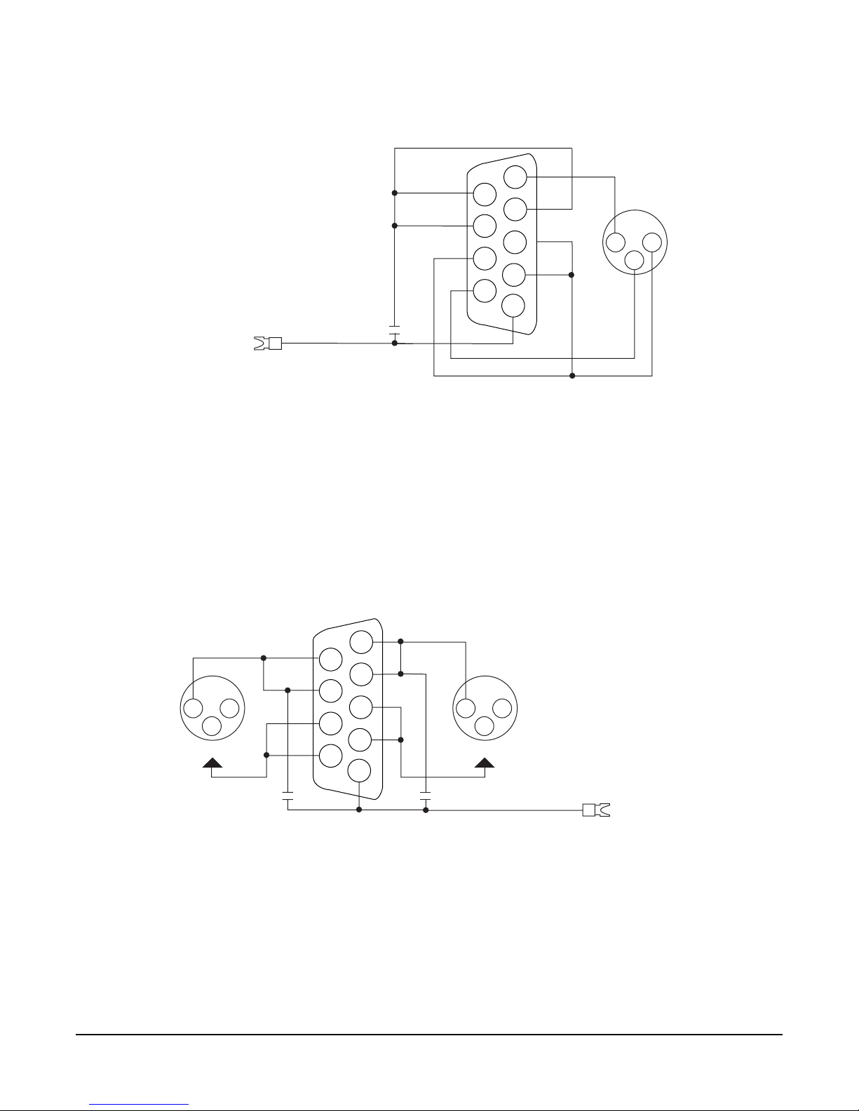
CCI-22 Dual Party-Line Interface 2-7
Figure 8: Cable Wiring Connection for Two RTS Party-Line Channels to the
Two Isolated RTS Lines
In Figure 8, each RTS channel is completely isolated from the other, including
the grounds.
Figure 9: Cable Wiring Connections between Two Isolated RTS Party-Line Channels
6
7
8
9
1
2
3
4
5
2
3
1
0.01 uF
7-in. 18 gauge wire
Spade Lug to
Chassis Ground
on IMF-3
XLR
DB-9F
6
7
8
9
1
2
3
4
5
2
3
1
2
3
1
7-in. 18 gauge wire
Spade Lug to
Chassis Ground
on IMF-3
XLR
DB-9F
XLR
To Pin
2 or 3
To Pin
2 or 3
0.01 uF0.01 uF

CCI-22 Dual Party-Line Interface
2-8
ADJUSTMENTS
POWER LED
The green “PL Power” LEDs indicate whether the interface channels are getting
+30 VDC power from the external party line to which they are connected.
LEVEL CONTROLS
The “Send” level controls affect the level of the audio signals from the matrix to
the external party line.
The “Recv” level controls affect the level of the audio from the party line to the
matrix. The level controls have a range of ±13 dB; they are normally set to the
midrange position.
SIDETONE NULL ADJUSTMENT
Sidetone is the sound of the operator’s voice in his headset. In interfaces, it is
necessary to null (minimize) the sidetone as much as possible when an external
party line is placed in the matrix environment. Ideally, there should be no
portion of the talk signal in the listen signal.
The CCI-22 features sophisticated built-in nulling circuitry, including a
test-tone generator and an accessory earphone. The earphone plugs into a phone
jack on the front panel. When the earphone is plugged in, it automatically
switches on a test tone and monitors the output of the null circuit.
Separate “R” (resistance), “L” (inductance), and “C” (capacitance) controls
compensate for each component of the line’s impedance, providing the best null
possible.
The null circuit is effective on line lengths between zero and 4000 ft. with
impedances in the range of 120 to 350 ohms, and can reduce local audio in the
received signal by more than 30 dB over the frequency range of 200 Hz to 8 kHz.
To null one channel of the CCI-22:
1. Connect the external party-line devices to the CCI-22 channel. Make sure that
any connected devices do not have their microphones on.
2. Plug the accessory earphone into the front-panel jack labeled “Test.” This will
disconnect the interface from the matrix and enable a test oscillator. The
oscillator produces a square wave with both low and high harmonics, allowing
testing of all frequencies. The test tone pulses approximately every 0.5
seconds.
3. While listening to the test tone in the earphone, adjust the “R” control until
the tone is at a minimum.
4. Repeat Step 3 with the “L” and “C” controls. Because these controls interact,
steps 3 and 4 will have to be repeated several times the test tone is minimized.
Continue adjustment until the tone is minimal. If a deep null cannot be
obtained, it is likely that something is wrong either with the wiring in the
external party line or with one of the other devices attached to it.

CCI-22 Dual Party-Line Interface 2-9
Following are some troubleshooting hints if a deep null cannot be obtained:
• If the “R” control is turned fully counter-clockwise, the line has either more
than one termination, or an excessive resistive load.
• If the “R” control is fully clockwise, then the line has no termination.
• The “L” control compensates for the low-frequency inductive and capacitive
elements the wiring of the external party line presents to the line. If the “L”
control is fully turned in either direction, it is likely that there is a problem in
the external party line. When a Clear-Com party line is connected, the “L”
control should be just to one side of its mid-pot position.
• The “C” control compensates for cable capacitance; the setting depends on the
length of the line. If the “C” control is fully counter-clockwise, it indicates a
very short line (under 10 ft.); this is a valid setting for a short line.
• If the “C” control is fully clockwise, it indicates an excessively long line (more
than 4000 ft.).
CONFIGURATION
Refer to the Eclipse Configuration System Instruction Manual for information on
configuring parameters from the matrix.

CCI-22 Dual Party-Line Interface
2-10
Table of contents
Other Clear-Com Recording Equipment manuals

Clear-Com
Clear-Com ECLIPSE MATRIX User manual

Clear-Com
Clear-Com PL-PRO EF-1M User manual

Clear-Com
Clear-Com FOR-22 User manual

Clear-Com
Clear-Com Encore TW-47 User manual

Clear-Com
Clear-Com ECLIPSE AES-6 User manual

Clear-Com
Clear-Com Eclipse IFB-104 User manual

Clear-Com
Clear-Com Eclipse 13.1 HX User manual

Clear-Com
Clear-Com LQ series User manual

Clear-Com
Clear-Com FIM-108 User manual

Clear-Com
Clear-Com LQ series User manual


