Megmeet MV300 Series User manual

1
MV300 Series Universal Vector Control Variable
Speed Drive
User Manual
Document Version: V1.0
Archive Date: 2015/07/29
BOM Code: R33010207
Shenzhen Megmeet Drive Technology Co., Ltd. provides full technical support for our
customers. Customers can contact local Megmeet offices or customer services centers, or
directly contact Megmeet headquarters.
Shenzhen Megmeet Drive Technology Co., Ltd.
All rights reserved. The contents in this document are subject to change without notice.
Shenzhen Megmeet Drive Technology Co., Ltd.
Address: 5th Floor, Block B, Unisplendor Information Harbor, Langshan Rd., Science &
Technology Park, Nanshan District, Shenzhen, 518057, China
Website: www.megmeet-drivetech.com
Tel: +86-755-86600500
Fax: +86-755-86600562
Service email: driveservice@megmeet.com

2
Foreword
Thank you for using the MV300 series universal vector control variable speed drive of Shenzhen
Megmeet Drive Technology Co., Ltd.
As new generation of integrated vector control platform, MV300 adopts the advanced integrated drive solution,
realizing the integration of asynchronous motor driving and the integration of torque control and speed control,
all driving indexes reach industry-leading level. MV300 can meet the high performance requirement of various
complex applications of customers. It has perfect anti-tripping ability and adjustability to the poor grid,
temperature, humidity and dust conditions, remarkably improving its reliability and adaptability.
MV300 adopts the modular extension design. It can not only meet the general requirements of the customer,
but also satisfy the industry and customized requirements through flexible extension. With the process
close-loop control, multi-functional input/output terminals, pulse frequency reference, simple PLC and
main/auxiliary reference control, MV300 can fully meet the requirements of complicated and high-precision
drive, which is of great value for reducing the system cost and improving the system reliability.
The MV300 can meet the requirements of the users for low noise and low EMI by adopting the integrated
EMC design and optimized PWM control technology.
The relevant precautions during the installation, wiring, parameter setting, troubleshooting and daily
maintenance will be detailed in this manual. To ensure the correct installation and operation of the MV300
series drive as well as its high performance, please read carefully this user manual before installing the
equipment. This manual shall be kept properly and delivered to the actual users of the drive.
Precautions for unpacking inspection
Please check carefully when unpacking the product:
·Whether the product has the damage signs;
·Whether the rated value in the nameplate is consistent with your order requirement.
We have implemented strict inspection on the manufacturing, package and delivery of the product. If there is
any error, please contact us or your distributor immediately.
We are engaged in the continuous improvement of drive. The relevant manuals provided by us are subject to
change without prior notice.

3
Safety Precaution
Operation without following instructions can cause death or severe personal injury.
Operation without following instructions can cause medium or slight personal injury or
damage to product and other equipment.
·Please install the product on the incombustible materials (e.g., metal), otherwise, fire may be caused.
·Do not place any combustible material near the product, otherwise, fire may be caused.
·Do not install the product in the environment with explosive gas, otherwise, explosion may be caused.
·Only qualified personnel can wire the drive, otherwise, electric shock may be caused.
·
Never wire the drive unless the input AC supply is completely disconnected, otherwise, electric shock may
be caused.
·The grounding terminal of the drive must be reliably grounded, otherwise, electric shock may be caused.
·The cover must be properly closed before power-up, otherwise, electric shock and explosion may be
caused.
·When powering up the drive that has been stored for over 2 years, the input voltage must be gradually
increased with the voltage regulator, otherwise, electric shock and explosion may be caused.
·Do not touch the terminals when the product is powered up, otherwise, electric shock may be caused.
·Do not operate the drive with wet hands, otherwise, electric shock may be caused.
·Maintaince operation can not be conducted until 10 minutes has passed after disconnecting the power
supply. Meanwhile, be sure to confirm that the chage LED is completely off and the DC bus voltage is
below 36V, otherwise, electric shock may be caused.
·Only qualified personnel can replace the components. Do not leave any wire or metal parts inside the
drive, otherwise, fire may be caused.
·After changing the control board, the parameters must be properly set before operating the drive,
otherwise, property damage may be caused.
·The bare parts of the terminal lugs in the main circuit must be wrapped with insulation tape, otherwise,
electric shock may be caused.
·
When carrying the drive, protect the operation panel and the cover against any stress, otherwise, the drive
may drop and cause human injury or property damage.
·Please install the drive on the place that can withstand the weight of the drive, otherwise, the drive may
drop and cause human injury or property damage.
·Do not install the drive in the environment with water splash (e.g., near the water pipe), otherwise, you
may suffer the property loss.

4
·Take care not to drop any foreign objects, such as the screws, gaskets and metal bars, into the drive,
otherwise, fire and property damage may be caused.
·
Do not install and operate the drive if it is damaged or its components are not complete, otherwise, fire and
human injury may be caused.
·Do not install the product in the place exposed to direct sunlight, otherwise, property damage may be
caused.
·Do not short circuit terminal P/B1 and terminal -DC, otherwise, fire and property damage may be caused.
·Cable lugs must be firmly connected to the terminals of main circuit, otherwise, property damage may be
caused.
·Do not connect AC 220V input to the control terminals other than terminal TA, TB and TC, otherwise,
property damage may be caused.

5
Contents
MV300 Series Universal Vector Control Variable Speed Drive ............................................ 1
Chapter 1 Introduction of MV300 Series Drive .................................................................... 7
1.1 Product model .....................................................................................................................................7
1.2 Product nameplate ..............................................................................................................................7
1.3 Product series......................................................................................................................................8
1.4 Technical specifications of product ......................................................................................................9
1.5 Drive structure ...................................................................................................................................11
1.6 Outline, mounting dimensions and gross weight of drive...................................................................11
1.7 Outline and mounting dimensions of operation panel........................................................................15
1.8 Outline and mounting dimensions of operation panel box.................................................................15
1.9 Options ..............................................................................................................................................16
Chapter 2 Drive Installation ............................................................................................... 18
2.1 Removal and installation of drive components ..................................................................................18
2.2 Installation environment.....................................................................................................................19
2.3 Mounting direction and space............................................................................................................19
Chapter 3 Wiring of Drive .................................................................................................. 21
3.1 Wiring and configuration of main circuit terminals .............................................................................22
3.2 Wiring and configuration of control circuit..........................................................................................30
3.3 Installation method for EMC requirements.........................................................................................41
Chapter 4 Quick Operation Guide for Drive....................................................................... 52
4.1 Drive operation panel ........................................................................................................................52
4.2 Drive running mode ...........................................................................................................................61
4.3 Initial power-up ..................................................................................................................................64
Chapter 5 Parameter List .................................................................................................. 66
5.1 Basic menu function code parameter table........................................................................................66
Chapter 6 Parameter Description .................................................................................... 114
6.1 System management parameters (Group P00)...............................................................................114
6.2 Status display parameters (Group P01)...........................................................................................118
6.3 Basic parameters (Group P02)........................................................................................................121
6.4 Motor parameters (Group P03)........................................................................................................130
6.5 Speed control parameters (Group P05)...........................................................................................135
6.6 Torque control parameters (Group P06) ..........................................................................................140
6.7 VF control parameters (Group P07) ................................................................................................145
6.8 Start and stop control parameters (Group P08) ...............................................................................148
6.9 Digital input/output parameters (Group P09) ...................................................................................152
6.10 Analog input/output terminal parameters (Group P10) ..................................................................170

6
6.11 Auxiliary function parameters (Group P11) ....................................................................................179
6.12 Advanced function parameters (Group P12) .................................................................................185
6.13 Multi-stage reference and simple PLC parameters (Group P13)...................................................188
6.14 Process PID parameters (Group P14)...........................................................................................194
6.15 Communication parameters (Group P15)......................................................................................201
6.16 Keyboard display setting parameters (Group P16)........................................................................202
6.17 Fieldbus option parameters (Group P40) ......................................................................................204
6.18 Protection and fault parameters (Group P97)................................................................................205
6.19 Drive parameters (Group P98) ......................................................................................................212
Chapter 7 Troubleshooting .............................................................................................. 214
7.1 Displaying exception and solutions..................................................................................................214
7.2 Operation exception and solutions ..................................................................................................221
Chapter 8 Maintenance ................................................................................................... 225
8.1 Daily maintenance...........................................................................................................................225
8.2 Periodical maintenance ...................................................................................................................226
8.3 Replacing wearing parts ..................................................................................................................226
8.4 Storage of drive ...............................................................................................................................227
Appendix 1 Modbus Communication Protocol................................................................. 228
1. Networking mode...............................................................................................................................228
2. Interface mode ..................................................................................................................................228
3. Communication mode........................................................................................................................228
4. Protocol format ..................................................................................................................................228
5. Protocol functions..............................................................................................................................230
6. Control parameters and status parameters of drive...........................................................................237
7. Expand access mode ........................................................................................................................244
8. Cautions ............................................................................................................................................249
9. CRC verification.................................................................................................................................251
10. Application example.........................................................................................................................253
11. Scaling of drive parameters .............................................................................................................255
Appendix 2 Braking Components .................................................................................... 256
Appendix 3 Warranty and Service ................................................................................... 259
Parameter record table..........................................................................................................................261
Wring diagram .......................................................................................................................................262

7
Chapter 1 Introduction of MV300 Series Drive
1.1 Product model
The description of the drive model on the nameplate indicates the information of the product series, such as
voltage class of power supply, power class, the software/hardware code of customized product, etc.
MV300 X - 4 T 0.75 - XX - XX
Product Series
G
1
1
P
General
Pump/Fan
0.75kW~400kW
Rated output power
00~ZZ:Software code
for customized product
00~ZZ:Hardware code
for customized product
S: Single-phase
T: Three-phase
2: 220V
4: 380V
1.2 Product nameplate

8
1.3 Product series
Table 1-1 Name and model of MV300G
Enclosure
mode Product model Rated capacity
(kVA)
Rated input
current
(A)
Rated output
current
(A)
Rated output power
(kW)
R2
MV300G-4T0.75 1.5 3.5 2.3 0.75
MV300G-4T1.5 3.0 5.1 3.7 1.5
MV300G-4T2.2 4.0 5.8 5.5 2.2
MV300G-4T3.7 5.9 10.5 8.8 3.7
R3
MV300G-4T5.5 8.5 14.5 13.0 5.5
MV300G-4T7.5 11.0 20.5 17.0 7.5
R4
MV300G-4T11 17.0 26.0 25.0 11
MV300G-4T15 21.0 35.0 32.0 15
R5
MV300G-4T18.5 24.0 38.5 37.0 18.5
MV300G-4T22 30.0 46.5 45.0 22
MV300G-4T30 40.0 62.0 60.0 30
R6
MV300G-4T37 50.0 76.0 75.0 37
MV300G-4T45 60.0 92.0 90.0 45
R7
MV300G-4T55 72.0 113.0 110.0 55
MV300G-4T75 100.0 157.0 152.0 75
R8
MV300G-4T90 116.0 180.0 176.0 90
MV300G-4T110 138.0 214.0 210.0 110
R9
MV300G-4T132 167.0 256.0 253.0 132
MV300G-4T160 200.0 307.0 304.0 160
R9P MV300G-4T200 250.0 385.0 380.0 200
R10
MV300G-4T220 280.0 430.0 426.0 220
MV300G-4T280 355.0 525.0 495.0 280
MV300G-4T315 445.0 590.0 585.0 315
R11
MV300G-4T355 500.0 665.0 650.0 355
MV300G-4T400 565.0 785.0 725.0 400
Table 1-2 Name and model of MV300P
Enclosure
mode Product model Rated capacity
(kVA)
Rated input
current
(A)
Rated output current
(A)
Rated output power
(kW)
R2
MV300P-4T0.75 1.5 3.5 2.3 0.75
MV300P-4T1.5 3.0 5.1 3.7 1.5
MV300P-4T2.2 4.0 5.8 5.5 2.2
MV300P-4T3.7 5.9 10.5 8.8 3.7
MV300P-4T5.5 8.5 14.5 13.0 5.5
R3 MV300P-4T7.5 11.0 20.5 17.0 7.5

9
R4
MV300P-4T11 17.0 26.0 25.0 11
MV300P-4T15 21.0 35.0 32.0 15
MV300P-4T18.5 24.0 38.5 37.0 18.5
R5
MV300P-4T22 30.0 46.5 45.0 22
MV300P-4T30 40.0 62.0 60.0 30
MV300P-4T37 50.0 76.0 75.0 37
R6
MV300P-4T45 60.0 92.0 90.0 45
MV300P-4T55 72.0 113.0 110.0 55
R7
MV300P-4T75 100.0 157.0 152.0 75
MV300P-4T90 116.0 180.0 176.0 90
R8
MV300P-4T110 138.0 214.0 210.0 110
MV300P-4T132 167.0 256.0 253.0 132
R9
MV300P-4T160 200.0 307.0 304.0 160
MV300P-4T200 250.0 385.0 380.0 200
R9P MV300P-4T220 280.0 430.0 426.0 220
R10
MV300P-4T280 355.0 525.0 495.0 280
MV300P-4T315 445.0 590.0 585.0 315
R11
MV300P-4T355 500.0 665.0 650.0 355
MV300P-4T400 565.0 785.0 725.0 400
1.4 Technical specifications of product
Table 1-3 Technical specifications of drive
Input power
Rated voltage (V)
Three-phase: 380V~480V; continuous fluctuation of voltage:
±10%, transient fluctuation of voltage: -15%~+10% (i.e. the
range is 323V~528V); Voltage unbalance rate: <3%, the
distortion rate complying with IEC61800-2
Rated input current (A) Please refer to Table 1-1 and Table 1-2.
Rated frequency (Hz) 50Hz/60Hz, fluctuation range: ±5%
Output power
Standard applicative motor (kW)
Please refer to Table 1-1 and Table 1-2.
Rated capacity (kVA)
Rated current (A)
Output voltage (V) Output with three-phase under rated input conditions: 0 ~ rated
input voltage, the error is less than ±3%
Output frequency (Hz) V/F: 0.00~3000.0Hz (unit: 0.01Hz); vector control: 0~650.00Hz
Overload capacity G: 1 min for 150% rated current, 0.5 s for 200% rated current
P: 1 min for 110% rated current, 1 s for 150% rated current
Operation control
features
Control mode Vector control without PG, V/F control without PG
Maximum output frequency 3000Hz for V/F control, 650Hz for vector control
Speed adjusting range 1: 200 (vector control without PG)

10
Speed control precision ±0.2% (vector control without PG)
Speed fluctuation ±0.3% (vector control without PG)
Torque response <10ms (vector control without PG)
Torque control The torque control precision is 7.5% when vector control without
PG
Startup torque 150% @ 0Hz (vector control without PG)
Product functions
Key functions
Fast tracking, over-torque/under-torque detection, torque limit,
multi-stage speed operation, multiple acceleration/deceleration
time switching, auto-tuning, S curve acceleration/deceleration,
slip compensation, fan speed control, skip frequency operation,
energy saving operation, PID adjustment (sleep function),
non-stop upon instantaneous power interruption, switching of
multi-command, MODBUS communication, Fieldbus
communication, drooping control, torque control, torque and
speed control mode switching, automatic restart, DC braking,
dynamic braking; simple PLC, dwell function, two sets of motor
parameters switching
Basic frequency 0.01Hz~3000.0Hz
Startup frequency 0.00Hz~60.00Hz
Frequency setting mode
Digital panel setting, terminal UP/DN setting, host device
communication setting, analog setting (AI1/AI2), terminal pulse
setting, fieldbus communication setting
Acceleration/deceleration time 0.1~3600.0 (unit can be selected among 0.1s, s and min)
Dynamic braking capacity Braking rate is 0.0~100.0%. Please refer to Table 1-7.
DC braking capacity
G:15kW and below have built-in braking unit as standard,
18.5kW~75kW can customize built-in braking unit,braking rate:
0.0~100.0%
P:18.5kW and below have built-in braking unit as standard,
22kW~90kW can customize built-in braking unit,braking rate:
0.0~100.0%
Terminal functions Please refer to the introduction of terminal functions for details.
Protection
function Refer to “Protection function” section for details.
Others
Efficiency ≥93% (7.5kW and below); ≥95% (45kW and below); ≥98%
(55kW and above)
Installation method Wall-mounted
Protection degree IP20
Cooling mode Air cooling with fan control
Environment
Operating site Indoor, away from direct sunlight, free from dust, corrosive gas,
combustible gas, oil mist, water vapor, water dripping or salt
Altitude Used at the place lower than 1000m, (derated at the place
above 1000m, derated 1% for every increase of 100m)
Ambient temperature -10℃~+40℃(derated when used in the ambient temperature of
40℃~50℃)
11
Humidity 5%~95%RH, non-condensing
Vibration less than 5.9m/s2(0.6g)
Storage temperature -40℃~+70℃
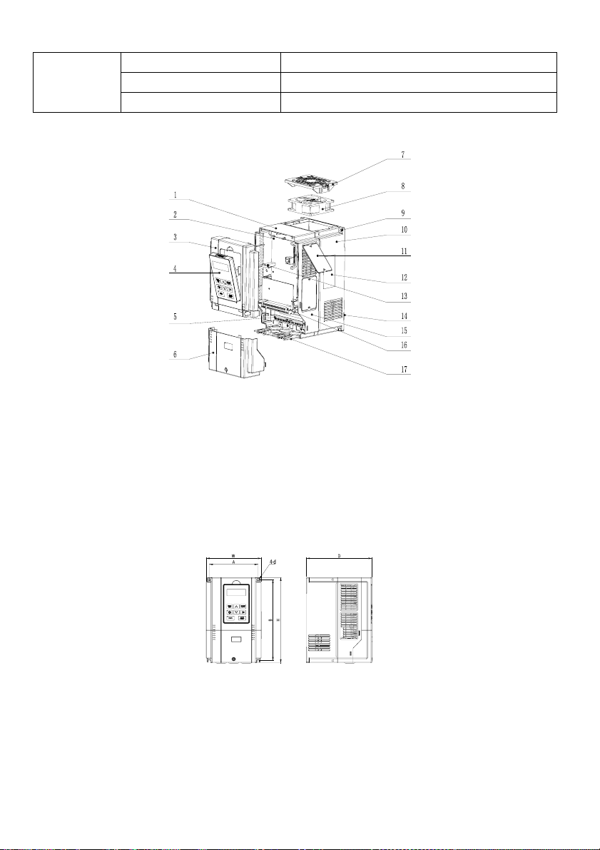
1.5 Drive structure
1. Mid-enclosure 2. Main control board 3. Upper cover 4. Operation panel 5. Main circuit wiring terminal
6. Lower cover 7. Fan guard 8. Fan 9. Mounting holes for complete unit 10. Bottom enclosure 11. Dustproof plate
12. Nameplate 13. Connector 14. Bottom plate 15. Mid-enclosure 16. Control terminal 17. Wiring plate
Fig. 1-1 Drive structure (taking R4 as an example)
1.6 Outline, mounting dimensions and gross weight of drive
There are four types of outlines as shown in Fig.1-2, Fig.1-3, Fig.1-4 and Fig.1-5. The outline, mounting
dimensions and gross weight are as shown in Table 1-4 and Table 1-5.
1. Enclosure R2~R4 ( G: 0.75kW-15kW; P:0.75kW-18.5kW)
Fig. 1-2 Outline, mounting dimensions for products of R2~R4
2. Enclosure R5~R8 (G: 18.5kW-110kW; P: 22kW-132kW)
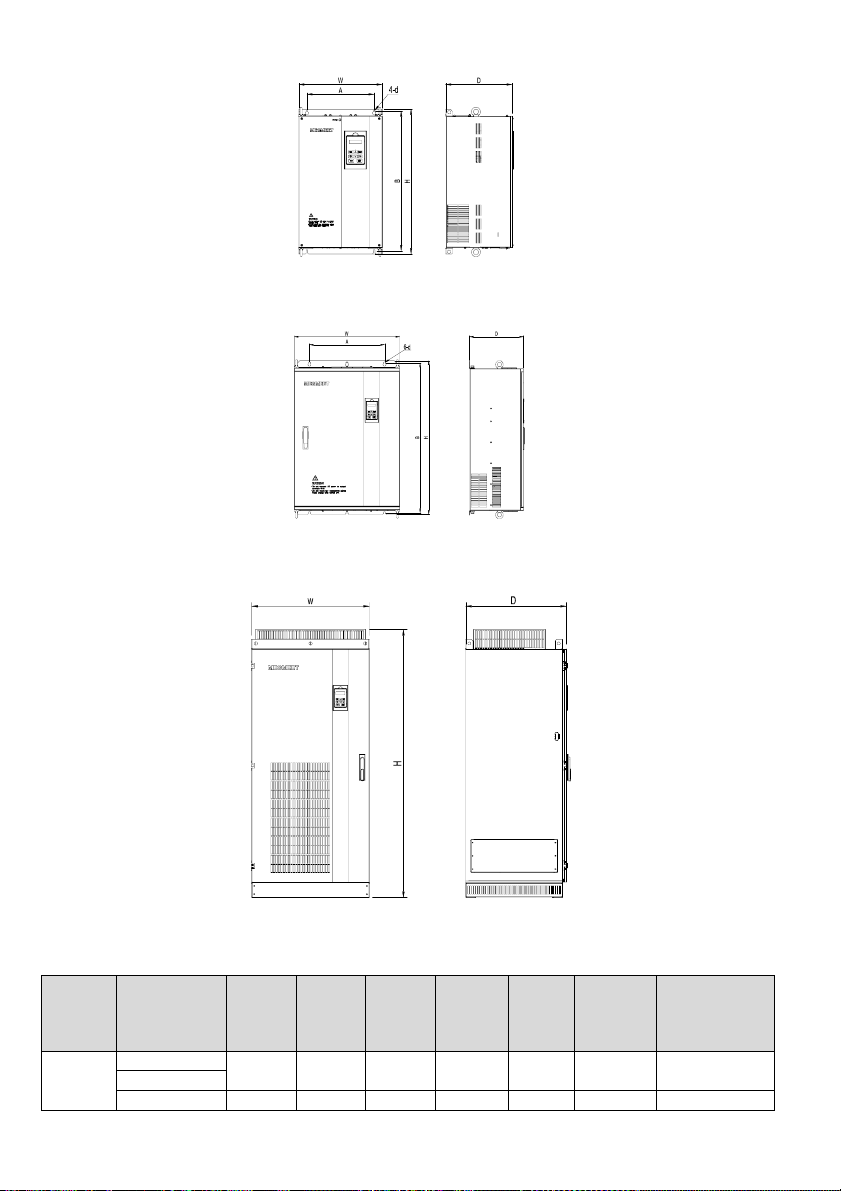
12
Fig. 1-3 Outline, mounting dimensions for products of R5~R8
3. Enclosure R9~R10 (G: 132kW-315kW; P: 160kW-315kW)
Fig. 1-4 Outline, mounting dimensions for products of R9~R10
4. Enclosure R11 (G: 355kW-400kW; P: 355kW-400kW)
Fig. 1-5 Outline, mounting dimensions for products of R11
Table 1-4 Outline, mounting dimensions and gross weight of MV300G
Enclosure
model Drive model A(mm)B(mm)H(mm)W(mm)D(mm)
Diameter of
mounting
aperture
(mm)
Gross weight
±0.5 (kg)
R2
MV300G-4T0.75 115 218 229 126 174 5.5 4
MV300G-4T1.5
MV300G-4T2.2 115 218 229 126 174 5.5 4

13
MV300G-4T3.7 4
R3 MV300G-4T5.5 137 236 249 155 198 5.5 4
MV300G-4T7.5
R4 MV300G-4T11 186 314.5 330 209 206 6.5 9
MV300G-4T15
R5
MV300G-4T18.5
220 437.5 451.5 284.5 213 6.5 19MV300G-4T22
MV300G-4T30
R6 MV300G-4T37 270 549 570 335 267 7 41
MV300G-4T45
R7 MV300G-4T55 270 579 600 335 292 7 49
MV300G-4T75
R8 MV300G-4T90 350 705 726.5 452 328.5 12 87
MV300G-4T110
R9 MV300G-4T132 350 827.5 849.5 500 350 12 154
MV300G-4T160
R9P MV300G-4T200 370 827.5 849.5 530 350 12 154
R10
MV300G-4T220
500 932 956 700 361.5 14 216MV300G-4T280
MV300G-4T315
R11 MV300G-4T355 --1624 710 610 -250
MV300G-4T400
Table 1-5 Outline, mounting dimensions and gross weight of MV300P
Enclosure
model Drive model A(mm)B(mm)H(mm)W(mm)D(mm)
Diameter of
mounting
aperture
(mm)
Gross weight
±0.5 (kg)
R2
MV300P-4T0.75 115 218 229 126 174 5.5 4
MV300P-4T1.5
MV300P-4T2.2
115 218 229 126 174 5.5 4
MV300P-4T3.7
MV300P-4T5.5
R3 MV300P-4T7.5 137 236 249 155 198 5.5 4
R4
MV300P-4T11
186 314.5 330 209 206 6.5 9MV300P-4T15
MV300P-4T18.5
R5
MV300P-4T22
220 437.5 451.5 284.5 213 6.5 19MV300P-4T30
MV300P-4T37
R6 MV300P-4T45 270 549 570 335 267 7 41
MV300P-4T55
R7 MV300P-4T75 270 579 600 335 292 7 49
MV300P-4T90
R8 MV300P-4T110 350 705 726.5 452 328.5 12 87
MV300P-4T132
R9 MV300P-4T160 350 827.5 849.5 500 350 12 154
MV300P-4T200
R9P MV300P-4T220 370 827.5 849.5 530 350 12 154
R10 MV300P-4T280 500 932 956 700 361.5 14 216
MV300P-4T315
R11 MV300P-4T355 --1624 710 609 -250
MV300P-4T400
14
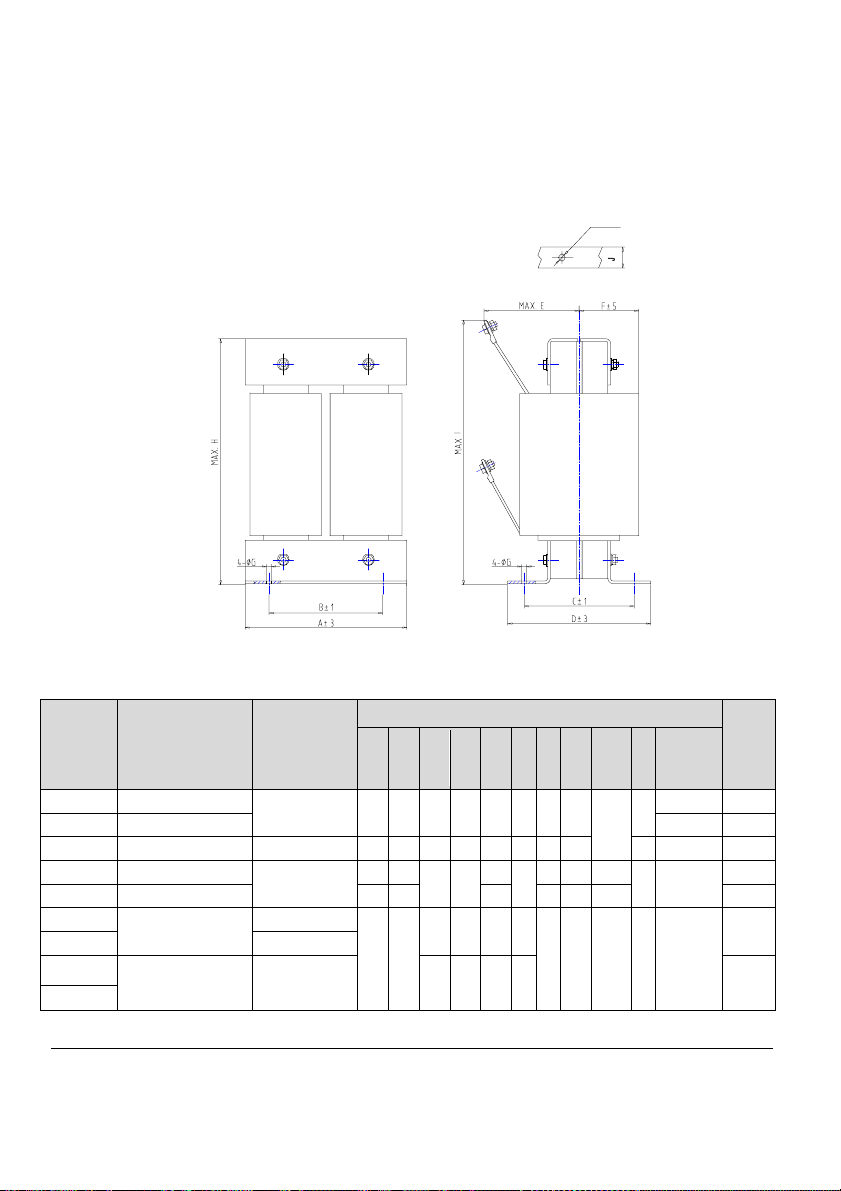
Note: For 75kWG drive or above, DC reactor is included in its standard configuration. The weight of DC
reactor is not included in the gross weight of the Table 1-4 and Table 1-5. Outline and dimensions of DC
reactor are shown below. For the drive of 355kWG/355kWP and above, DC reactor is included in its standard
configuration.
Diameter of terminal
Enlarged view of terminal
Mounting
hole
Mounting
hole
Fig. 1-6 Dimensions of DC reactor
Table 1-6 Mechanical Parameters of DC Reactor
Applicable
drive(kW)Model of DC reactor
Recommended
size of copper
(mm2)
Size(mm)Gross
weight
(kg)
A B C D E F G H I J
Diameter
of
terminal
75G DCL-0160-UIDH-7908
60 160 100 98 130 95 65 9 215
/
20
Ф8 14.5
90G/90P DCL-0180-UIDH-7908 Ф10 16
110G/110P DCL-0250-UIDH-7908 100 210 176 115 150 125 84 11 255 30 Ф12 25.5
132G/132P JSY-3674
150
200 170
135 171
120
85
10 260 280
30 Ф12
28
160G/160P JSY-3449 210 180 130 12 280 320 32
200G/200P
JSY-3066-1
200
220 190
135 171 150 90
12 315 340 40 Ф15
40
220G/220P 250
280G/280P
JSY-3067-1 325 145 181 160 95 45
315G/315P
Note
1.Columns B and C in Table 1-6 are the sizes of mounting holes of DC reactor.

15
2.For the drive of 75kWG~110kWG/110kWP, the DC reactor is packed separately with a wooden box, so the
gross weight includes the weight of the DC reactor and the wooden box.
3.DC reactor should be installed at the bottom of the cabinet if it is to be installed inside a cabinet. The
clearance between reactor and the drive should be at least 35cm, and the reactor should be as far away from
the air inlet port of the drive as possible. If ventilation is poor in the cabinet, it is recommended to increase fan
forced air cooling for the reactor to avoid high ambient temperature.
1.7 Outline and mounting dimensions of operation panel
Fig. 1-7 Outline and mounting dimensions of operation panel
1.8 Outline and mounting dimensions of operation panel box
The outline dimensions of the box used for mounting operation panel is as shown in Fig. 1-8.
Fig. 1-8 Outline dimensions of operation panel box
The mounting dimensions of the operation panel box is as shown in Fig. 1-9.
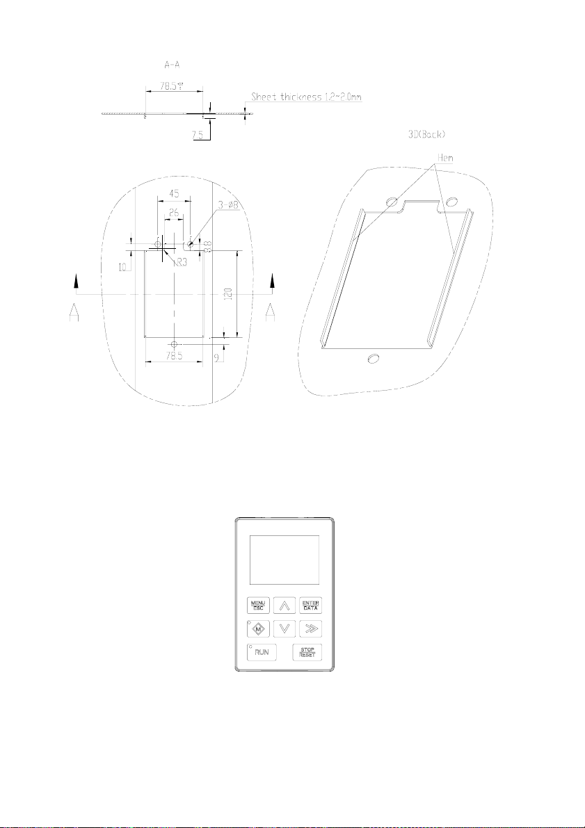
16
Fig. 1-9 Mounting dimensions of operation panel box
1.9 Options
1.9.1 LCD operation panel (reserved)
Fig. 1-10 LCD operation panel
1.9.2 Braking components
The information of braking components is as shown in Table 1-7.

17
Table 1-7 Braking components of MV300
Model Braking components
G
15kW and below Built-in braking unit.
18.5kW ~ 75kW Built-in braking unit, need
customization.
90kW and above Separate braking unit, see
Appendix 2.
P
18.5kW and below Built-in braking unit.
22kW ~ 90kW Built-in braking unit, need
customization.
110kW and above Separate braking unit, see
Appendix 2.
18
Chapter 2 Drive Installation
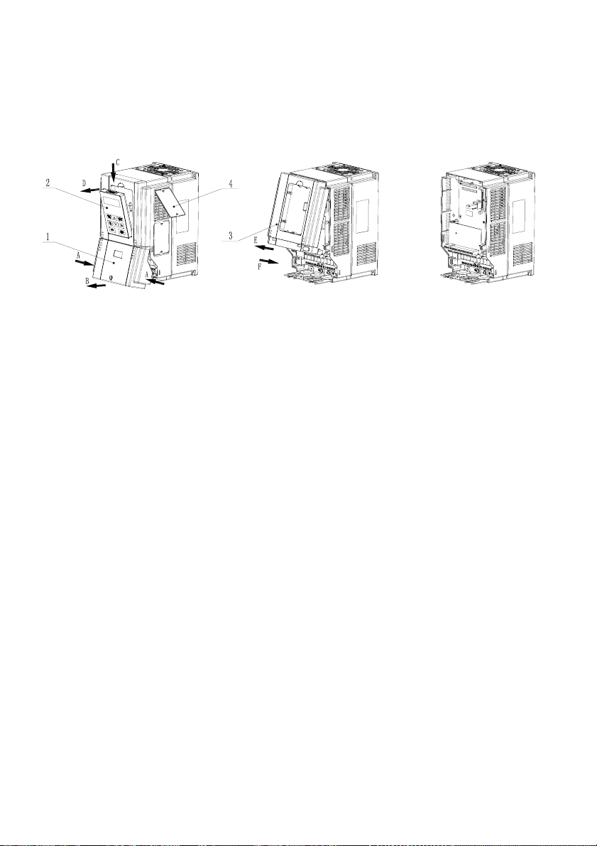
2.1 Removal and installation of drive components
1. Lower cover 2. Operation panel 3. Upper cover 4. Dustproof plate
Fig. 2-1 Removal and installation of drive components (taking R4 as an example)
1. Removal and installation of lower cover
Removal: Loosen the fixing bolts of the lower cover with the screwdriver, press the snap-fits on both sides in
direction A, make snap-fits off with the mid-enclosure and then lift the lower cover in direction B. Now, the
lower cover is removed.
Installation: Insert the insertion piece at the top of the lower cover into the upper cover, press both sides of the
lower cover with both hands in direction A so that the snap-fits can enter into the mid-enclosure, then tighten
the fixing bolts of the lower cover with the screwdriver. Now, the lower cover is installed.
2. Removal and installation of operation panel
Removal: Insert your finger into the square hole above the operation panel, press the clip in direction C and
then separate the upper section of the operation panel with the upper cover in direction D, then separate the
connector with the operation panel. Now, the operation panel is removed.
Installation: Ensure the display of the operation panel face upwards, press the operation panel into its
box while keeping them parallel. Now, the operation panel is installed.
3. Removal and installation of upper cover
Removal: Loosen the fixing bolts of the upper cover with the screwdriver, pull in direction E to separate the
upper cover from the mid-enclosure (if necessary, press the snap-fits of the upper cover from its side with the
straight screwdriver). Now, the upper cover is removed.
Note: Do not directly remove the upper cover with the operation panel on it. The operation panel should be
removed before removing the upper cover to avoid damages to the connecting base between the operation
panel and control board, which may cause unreliable contact between the operation panel and the control
board.
Installation: Press the lower part of the upper cover in direction F so that its snap-fits can enter into the
mid-enclosure, and then tighten the fixing bolts of the upper cover with the screwdriver. Now, the upper cover
is installed.
4. Removal and installation of dustproof plate
19
Removal: It is recommended to push both snap-fits of the dustproof plate from the inside of the enclosure with
tools, so that the snap-fits can be separated from the mid-enclosure. Now, the dustproof plate is removed.
Note: Removing the dustproof plate from the outside of the enclosure directly may damage it or the
mid-enclosure.
Installation: Place the snap-fit on one end of the dustproof plate into the mid-enclosure, move the dustproof
plate to another end while pressing it till the snap-fit on another end also enters into the mid-enclosure. Now,
the dustproof plate is installed.
Note: Do not press the dustproof plate forcibly if it is deformed, otherwise, it may be damaged.
2.2 Installation environment
When selecting the installation environment, the following issues should be taken into account:
·The ambient temperature should be within -10 ~40 . If the temperature is between 40 ~50 , derating℃℃ ℃℃ is
required.
·The humidity should be within 5%~95%RH, non-condensing.
·The vibration at the installation place should be less than 5.9m/s2(0.6g).
·The device should be protected from the direct sunlight.
·The device should be mounted in the location free of dust and metal powder.
·Do not install the device in the place with corrosive gas and explosive gas.
If there is any special installation requirement, please consult our company.
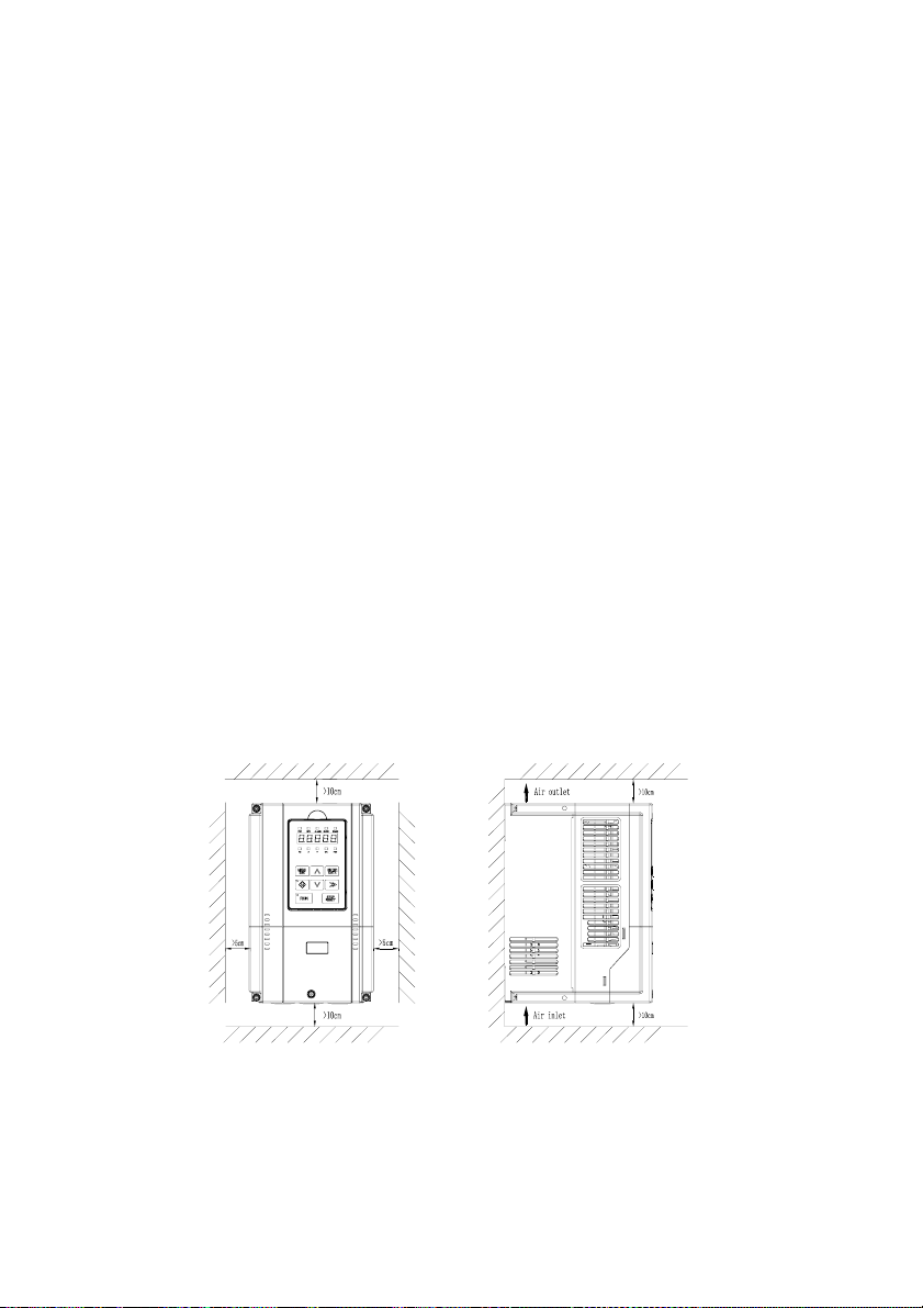
2.3 Mounting direction and space
In general, the drive shall be installed vertically to avoid poor heat dissipation.
For the installation spacing and distance requirement, please refer to Fig.2-2 and Fig.2-3.
Fig. 2-2 Installation spacing for models of 45kWG/55kWP and below
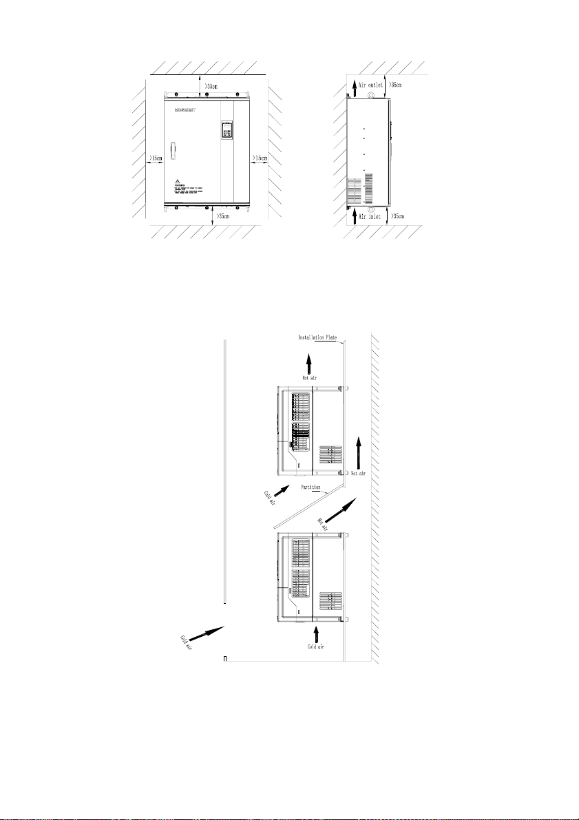
20
Fig. 2-3 Installation spacing for models of 55kWG/75kWP and above
When more than two drives are mounted in the up-down installation mode, the partition plate should be
installed between them, so as to avoid the influence of the heat dissipation from the bottom drive on the top
one, as shown in Fig.2-4.
Fig. 2-4 Installation of multiple drives
This manual suits for next models
40
Table of contents
Other Megmeet DC Drive manuals


