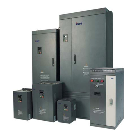
Megmeet MV600L Series User manual

1
MV600L Series Drive Special for Lifting
Simple User Manual
Document Version: V1.0
Archive Date: 2015/09/22
BOM Code: R33010233
Shenzhen Megmeet Drive Technology Co., Ltd. provides full technical support for our
customers,customers can contact local Megmeet offices or customer service centers, or
directly contact Megmeet headquarters.
Shenzhen Megmeet Drive Technology Co., Ltd.
All rights reserved. The contents in this document are subject to change without notice.
Shenzhen Megmeet Drive Technology Co., Ltd.
Address: 5th Floor, Block B, Unisplendor Information Harbor, Langshan Rd., Science &
Technology Park, Nanshan District, Shenzhen, 518057, China
Website: www.megmeet-drivetech.com
Tel: +86-755-86600500
Fax: +86-755-86600562
Service email: crane@megmeet.com

2
Foreword
MV600L is a special drive for lifting industry developed by Shenzhen Megmeet Drive Technology Co., Ltd.
For lifting industry security is the top priority, as a key component of lifting industry drive, MV600L drive
performs full design and verification for security in device selection, margin design, logic design, fault
protection and other aspects. Reliability, rugged and durable is another requirement for lifting special drive,
unlike factory use drive, lifting drive is used in outdoor, environment is more severe than the factory in power
grid, lightning, atmospheric environment, vibration, moving and other aspects, strengthening the drive
resistance to moisture, salt spray corrosion, power grid under-voltage, phase loss, lightning, vibration,
misoperation makes us pay extra time and cost. Finally stand on the user's point of view, start from the ease
of use and maintenance, innovatively propose drive working mode, software curing different modes of
operating logic and default parameters, remove unwanted drive general functions for lifting industry, make use
and maintenance of MV600L simple.
Megmeet drive pioneered the "working mode" in the lifting industry. Cranes generally have lifting, slewing,
luffing, walking and other institutions, MV600L selects these transmission station through a function code, and
it will bring change of control logic and related function code defaults, so as to be convenient for the user.
MV600L selects a large storage capacity of the CPU, it can be used to save motor parameters of the lifting
industry commonly used to solve customer problems of obtaining motor parameters.
As a drive special for lifting, MV600L has been used by a number of leading enterprises, including the
Zoomlion, XCMG, DAHAN and so on. Industry applications have been more than 20000 units. Its high
performance, high reliability, easy to use and maintain was highly recognized.
Precautions for unpacking inspection
Please check carefully when unpacking the product:
·Whether the product has the damage signs;
·Whether the rated value in the nameplate is consistent with your order requirement.
We have implemented strict inspection on the manufacturing, package and delivery of the product. If there is
any error, please contact us or your distributor immediately.
We are engaged in the continuous improvement of drive. The relevant manuals provided by us are subject to
change without prior notice.
Note:
This manual is MV600L drive special for lifting simple manual, it is provided together with the drive, only for
engineers with a certain drive professional knowledge to use.To obtain detailed user manual, please contact
the megmeet company, crane @ megmeet.com.

3
Contents
MV600L Series Drive Special for Lifting .............................................................................. 1
Chapter 1 Introduction of MV600L Series Drive .................................................................. 4
1.1 Product model .....................................................................................................................................4
1.2 Product series......................................................................................................................................4
1.3 Technical specifications of product ......................................................................................................5
1.4 Outline, mounting dimensions and gross weight of drive.....................................................................6
Chapter 2 Wiring of Drive .................................................................................................... 8
2.1 Wiring and configuration of main circuit terminals ...............................................................................8
2.2 Wiring and configuration of control circuit..........................................................................................11
Chapter 3 Parameter List .................................................................................................. 17
Chapter 4 Parameter Description ...................................................................................... 41
4.1 System management parameters (Group P00).................................................................................41
4.2 Motor parameters (Group P03)..........................................................................................................42
4.3 Speed control parameters (Group P05).............................................................................................43
4.4 Start and stop control parameters (Group P08).................................................................................44
4.5 Auxiliary function parameters (Group P11) ........................................................................................45
4.6 Multi-stage reference and simple PLC parameters (Group P13).......................................................46
4.7 Slewing control parameters (Group P13) ..........................................................................................47
4.8 Lifting control parameters(Group P26) ..............................................................................................47
4.9 Brake control parameter(Group P60) ................................................................................................48
4.10 Special function parameters for lifting control(Group P61) ..............................................................49
Chapter 5 MV600L Series Drive Special for Lifting Debugging Guide............................... 51
5.1 Slewing application typical wiring ......................................................................................................52
5.2 Luffing application typical wiring ........................................................................................................53
5.3 Lifting application(closed loop/open loop vector) typical wiring .........................................................54
Chapter 6 Troubleshooting ................................................................................................ 58
6.1 Displaying exception and solutions....................................................................................................58
6.2 Operation exception and solutions ....................................................................................................66
Appendix 1 Recommended Braking Unit and Resistor...................................................... 69
Appendix 2 Indentification of LED Display Symbols .......................................................... 71
Appendix 3 Warranty and Service ..................................................................................... 72

4
Chapter 1 Introduction of MV600L Series Drive
1.1 Product model
The description of the drive model on the nameplate indicates the information of the product, such as product
series, voltage class of power supply, power class, the software/hardware code of customized product, etc.
MV600 L- 4 T 5.5- XX AX
Product series
L: Special for lifting
4: 400V T: Three-phase
:Software code
for customized product
9Z~A0
:Hardware code
for customized product
99~00
Rated output power
400kW~kW2.2
1.2 Product series
Table 1-1 Name and model of drive
Enclosure
model Product model Rated capacity
(kVA) (HD)
Rated input
current (A)
Rated output
current (A)
Rated output
power (kW)
R2
MV600L-4T2.2 4.0 5.8 5.5 2.2
MV600L-4T3.7 5.9 10.5 8.8 3.7
R3
MV600L-4T5.5 8.5 14.5 13.0 5.5
MV600L-4T7.5 11.0 20.5 17.0 7.5
R4
MV600L-4T11 17.0 26.0 25.0 11
MV600L-4T15 21.0 35.0 32.0 15
MV600L-4T18.5 24.0 38.5 37.0 18.5
R5
MV600L-4T22 30.0 46.5 45.0 22
MV600L-4T30 40.0 62.0 60.0 30
MV600L-4T37 50.0 76.0 75.0 37
R6 MV600L-4T45 60.0 92.0 90.0 45
R7
MV600L-4T55 72.0 113.0 110.0 55
MV600L-4T75 100.0 157.0 152.0 75
R8 MV600L-4T90 116.0 180.0 176.0 90

5
MV600L-4T110 138.0 214.0 210.0 110
MV600L-4T132 167.0 256.0 253.0 132
R9
MV600L-4T160 200.0 307.0 304.0 160
MV600L-4T200 250.0 385.0 380.0 200
R10
MV600L-4T220 280.0 430.0 426.0 220
MV600L-4T280 355.0 525.0 495.0 280
R11
MV600L-4T315 388.0 590.0 585.0 315
MV600L-4T355 437.6 665.0 650.0 355
MV600L-4T400 516.5 785.0 725.0 400
1.3 Technical specifications of product
Table 1-2 Technical specifications of drive
Input/
Output
Rated voltage (V)
Three-phase: 380V~480V; continuous fluctuation of voltage: ±10%, transient
fluctuation of voltage: -15%~+10% (i.e. the range is 323V~528V); voltage
unbalance rate: <3%, the distortion rate complies with IEC61800-2
Rated frequency (Hz) 50Hz/60Hz, fluctuation range: ±5%
Output voltage (V) Output with three-phase under rated input conditions, 0 ~ rated input voltage, the
error is less than ±3%
Output frequency (Hz) Unit: 0.01Hz; 0~650.00Hz
Overload capacity 1 min for 150% rated current, 0.5 s for 200% rated current
Operation
control
features
Control mode Vector control without PG, vector control with PG, V/F control without PG, V/F
control with PG
Speed adjusting range 1: 200 (vector control without PG); 1: 1000 (vector control with PG)
Speed control
precision ±0.2% (vector control without PG); ±0.02% (vector control with PG)
Speed fluctuation ±0.3% (vector control without PG); ±0.1% (vector control with PG)
Torque response <5ms (vector control with PG); <10ms (vector control without PG)
Torque control The torque control precision is 7.5% when vector control without PG, and 5%
when vector control with PG
Startup torque 150% @ 0Hz (vector control without PG); 200% @ 0Hz (vector control with PG)
Key functions
Brake logic control, with load with speed, with voltage with speed, off load
detection, overspeed detection, brake reliability detection, torque limit, over
torque/under torque detection, multi-stage speed operation, multiple
acceleration/deceleration time switching, auto-tuning, S curve
acceleration/deceleration, slip compensation, fan speed control, skip frequency
operation, switching of multi-command, MODBUS communication, drooping
control, torque control, torque and speed control mode switching, DC braking,
dynamic braking
Industry
features Working mode
Slewing mode: Multi-motor flexible vector control; built-in vortex control signal
Luffing mode: Built-in brake release / closing logic; with load with speed control
Closed loop lifting mode: Built-in brake release / closing logic; with load with
speed control
Open loop lifting mode: Built-in brake release / closing logic; with load with
speed control

6
Motor parameter called Function code [P00.05] built-in classic parameters of mainstream motor of lifting
industry
A key recovery When the user has set all function codes, you can store all the changes of
function codes, then use a key to recover all the changed function code.
Protection
function
Protection function of
general drive
Over-current ; over-voltage; short circuit; drive / motor overload; input / output
phase loss; overheating; encoder fault
Brake mechanism
failure Er.bCF, Er.bSF, Er.FbL, Er.Fbr
Security protection Speed deviation protection, overspeed protection, off load protection
Others
Cooling mode Forced cooling
Operating site Indoor, away from direct sunlight, free from dust, corrosive gas, combustible
gas, oil mist, water vapor, water dripping or salt
Altitude Used at the place lower than 1000m (derated at the place above 1000m, derated
1% for every increase of 100m)
Ambient temperature -10 ~+40 (derated when used in the ambient temperature of 40 ~50 )℃℃ ℃℃
Humidity 5%~95%RH, non-condensing
Vibration Less than 5.9m/s2(0.6g)
Storage temperature -40 ~+70℃℃
Efficiency ≥93% (7.5kW and below); ≥95% (45kW and below); ≥98% (55kW and above)
Installation method Wall-mounted
1.4 Outline, mounting dimensions and gross weight of drive
There are two types of outlines as shown in Fig. 1-1and Fig. 1-2. The outline, mounting dimensions and gross
weight are as shown in Table 1-3.
1. Enclosure R2~R10 (2.2kW-280 kW)
Fig. 1-1 Outline, mounting dimensions for products of 2.2kW-280kW
2. Enclosure R11 (315kW-400 kW)

7
Fig. 1-2 Outline, mounting dimensions for products of 315kW-400kW
Table 1-3 Outline, mounting dimensions and gross weight
Enclosure
model Drive model A(mm) B(mm) H(mm) W(mm) D(mm)
Diameter
of
mounting
aperture
(mm)
Gross
weight
±0.5
(kg)
R2 MV600L-4T2.2 115 218 229 126 174 5.5 4
MV600L-4T3.7
R3 MV600L-4T5.5 137 236 249 155 198 5.5 4
MV600L-4T7.5
R4
MV600L-4T11
186 314.5 330 209 206 6.5 9MV600L-4T15
MV600L-4T18.5
R5
MV600L-4T22
220 437.5 451.5 284.5 213 6.5 19MV600L-4T30
MV600L-4T37
R6 MV600L-4T45 270 549 570 335 267 7 41
R7 MV600L-4T55 270 579 600 335 292 7 49
MV600L-4T75
R8
MV600L-4T90
350 705 726.5 452 328.5 12 87MV600L-4T110
MV600L-4T132
R9 MV600L-4T160 350 827.5 849.5 500 350 12 154
MV600L-4T200
R10 MV600L-4T220 500 932 956 700 361.5 14 216
MV600L-4T280
R11
MV600L-4T315
- - 1624 710 610 - 250MV600L-4T355
MV600L-4T400

8
Chapter 2 Wiring of Drive
2.1 Wiring and configuration of main circuit terminals
Terminal type 1
Applicable models: MV600L-4T2.2~ MV600L-4T18.5
Terminal type 2
Applicable models: MV600L-4T22~ MV600L-4T37
Terminal type 3
Applicable models: MV600L-4T45
Terminal type 4
Applicable models: MV600L-4T55~ MV600L-4T75
R/L1 S/L2 T/L3
TOP
+DC W/T3P/B1 B2 -DC U/T1 V/ T2
BOTTOM
Terminal (terminal type 1-4) Function
R/L1, S/L2,T/L3 Three-phase AC 380V input terminals
+DC, P/ B 1 Reserved for external DC reactor, connected with copper bus
upon delivery
P/B1, B2 Reserved for external braking resistor
-DC DC negative bus output terminals
U/T1, V/T2, W/T3 Three-phase AC output terminals
Terminal type 5
Applicable models: MV600L-4T90~ MV600L-4T280

9
Terminal Function
R/L1, S/L2, T/L3 Three-phase AC 380V input terminals
P, + D C Reserved for external DC reactor, connected with copper bus
upon delivery
-DC DC negative bus output terminals
P, -DC Reserved for external braking unit
U/T1, V/T2, W/T3 Three-phase AC output terminals
Terminal type 6
Applicable models: MV600L-4T315 ~ MV600L-4T400
Terminal Function
R/L1, S/L2, T/L3 Three-phase AC 380V input terminals
P, + D C Reserved for external DC reactor, connected with copper bus
upon delivery
P, N Reserved for external braking unit
-DC DC negative bus output terminals
U/T1, V/T2, W/T3 Three-phase AC output terminals
2.1.1 Drive connection
Table 2-1 Recommended fuse capacity and cross section area of the copper-cored insulation wire
Model
Incoming line
protection
Main circuit
(mm2)
Control circuit
(mm2)
Fuse (A) Input
wire
Output
wire
Control terminal
wire
MV600L-4T7.5 20 4 4 1
MV600L-4T11 32 6 6 1
MV600L-4T15 35 6 6 1
MV600L-4T18.5 50 6 6 1
MV600L-4T22 63 10 10 1
MV600L-4T30 80 16 16 1
MV600L-4T37 100 25 25 1
MV600L-4T45 125 25 25 1
MV600L-4T55 160 35 35 1
MV600L-4T75 200 70 70 1
MV600L-4T90 250 70 70 1
MV600L-4T110 315 95 95 1

10
MV600L-4T132 400 150 150 1
MV600L-4T160 450 185 185 1
MV600L-4T200 560 240 240 1
MV600L-4T220 630 150×2 150×2 1
MV600L-4T280 800 185×2 185×2 1
MV600L-4T315 800 150×2 150×2 1
MV600L-4T355 800 150×2 150×2 1
MV600L-4T400 1000 150×2 150×2 1
Note: The parameters listed in this table are recommended values.
2.1.2 Wiring for basic operation
4V2~0
Fig. 2-1 Basic wiring diagram for products of 75kW and below

11
P
-DC
B1
B2
-10V~+10V
MV600L
PE
AI3-
AI3+
GND
AI1/ AI2
X1
X2
X3
X4
X5
X6
X7
X8
-10
+10
COM
P24
PLC
R/L1
S/L2
T/L3
+DC -DC
U
V
W
PE
12C
COM
PE
GND
AO1
Y2
TB
TA
TC
BRA
BRC
M
PG
COM
RS485+
RS485-
AI1 AI2
0~10V
AO1 AO2
0~20mA
-10V~10V
0~20mA
AO2
B-
B+
A-
A+
P
PE
Y1
P24
DCL DC reactor
(External, default configuration)
Braking unit and resistor
(External, optional part)
Three-phase
380V
50/60Hz
Multi-function input 1
Multi-function input 2
Multi-function input 3
Multi-function input 4
Multi-function input 5
Multi-function input 6
Multi-function input 7
Multi-function input 8
Analog input
Analog differential input
Standard RS485
commmunication
port
Relay output 2
Relay output 1
Output 2 Open collector output
Frequency meter
(open collector output)
pulse signal output
4V2~0
DC voltage/current meter
Voltage/current signal
Fig. 2-2 Basic wiring diagram for products of 90kW and above
2.2 Wiring and configuration of control circuit
2.2.1 The arrangement sequence diagram of the control circuit terminals
Fig. 2-3 The arrangement sequence diagram of the control circuit terminals

12
2.2.2 Wiring of control circuit terminals
Type Terminal Name Function Specification
Shield PE Shield
grounding
Used for the grounding of the shielded
layer of the wire. The shielded layer of
the analog signal wire, 485
communication wire and PG cable
wire can be connected to this terminal.
Connected to the main circuit wiring
terminal internally
Power
supply
+10 +10V power
supply
To provide +10V reference power for
external load
Allowable maximum output current:
10mA
-10 -10V power
supply
To provide -10V reference power for
external load
Allowable maximum output current:
10mA
GND +10V/-10V
power GND
The reference ground for analog signal
and +10V/-10V power Internal isolated with COM
Analog
input
AI1
Analog
single-end
input AI1
To receive the single-end analog
voltage or current input with the analog
input voltage/current selected via the
jumper (reference grounding: GND)
Input voltage range: -10V~10V (input
resistance: 20kΩ), resolution: 1/4000
Input current range: 0mA~20mA (input
resistance: 246Ω), resolution: 1/2000
AI2
Analog
single-end
input AI2
AI3+
Analog voltage
differential
input AI3+ or
analog voltage
single-end
input
For the analog voltage differential input,
the AI3+ is the non-inverting input
terminal and the AI3- is the inverting
input terminal.
For the analog voltage single-end input,
AI3+ is the signal input terminal and
AI3- shall be connected to GND
(reference grounding: GND).
Input voltage range: -10V~10V (input
resistance: 15kΩ), resolution: 1/4000
AI3-
Analog voltage
differential
input AI3- or
analog voltage
single-end
input
Analog
output
AO1 Analog output
1
When providing the analog
voltage/current output, it can represent
27 values. The analog output of the
voltage/current is selected via the
jumper. (reference grounding:GND)
Voltage output range: 0/2~10V
Current output range: 0/4~20mA
AO2 Analog output
2
Communi
cation
RS485+ RS485
communication
interface
Positive end of 485 differential signal
(reference grounding: GND)
Standard RS485 communication
interface.
Please use twisted pair wire or shielded
wire.
RS485- Negative end of 485 differential signal
(reference grounding: GND)

13
Encoder
A+,A- Encoder phase
A signal
Differential input signal of encoder
phase A
Maximum input frequendy≤100kHz
B+,B- Encoder phase
B signal
Differential input signal of encoder
phase B
12C
Encoder power
supply (special
for lifting)
To provide power supply for external
encoder (reference grounding: COM)
Output voltage: +12V
Maximum output current: 250mA
Multi-funct
ional input
terminal
X1
Multi-functional
input terminal
1
It can be set as the digital input terminal
with multiple functions.The factory
default settings for X1 and X2 are FWD
(forward running command terminal)
and REV (reverse running command
terminal) respectively. The running
command terminals can be set with
other input terminals and can realize the
“three-wire control” function with the
third input terminal. For details, please
refer to the introduction of the functions
about input terminals P09.00~P09.07
and the introduction of the “two-wire
control” and “three-wire control”
functions (P09.08) in “Digital
input/output parameters” (Group P09)
(common terminal: PLC).
Opto-isolated input, please refer to the
introduction to the multifunctional
input/output terminal wiring
Input resistance: R=3.1kΩ;
maximum input frequency: 200Hz
Input voltage range: 20V~30V
X2
Multi-functional
input terminal
2
X3
Multi-functional
input terminal
3
X4
Multi-functional
input terminal
4
X5
Multi-functional
input terminal
5
X6
Multi-functional
input terminal
6
X7
Multi-functional
input terminal
7
In addition to acting as an ordinary
multi-functional terminals (same as
X1~X6), X7 and X8 can also be set as
the high-speed pulse input terminal. For
details, please refer to the introduction
to the functions of input terminals
P09.00~P09.07 in “Digital input/output
parameters” (Group P09) (common
terminal: PLC).
The equivalent diagram for the
opto-isolated input is shown as above,
please refer to the introduction to wiring
for the multi-functional input/output
terminals.
Input resistance: R=2kΩ
Maximum input frequendy: 100kHz
Input voltage range: 20V~30V
X8
Multi-functional
input terminal
8

14
Multi-funct
ional
output
terminal
Y1
Open collector
output terminal
1 / DO pulse
output terminal
It can be set as the digital output
terminal with multiple functions and also
can be reused as DO pulse output
terminal, which is selected by the
function code P09.17. For details,
please refer to the introduction to the
functions of P09.17 or P09.29 in “Digital
input/output parameters” (Group P09)
(common terminal: COM).
Opto-isolated output
Maximum operating voltage: 30V
Maximum output current: 50mA
The DO pulse output frequency range
depends on P09.30 and the maximum
value is 50kHz
Y2
Open collector
output terminal
2
It can be set as the digital output
terminal with multiple functions. For
details, please refer to the introduction
to the functions of P09.18 in “Digital
input/output parameters” (Group P09)
(common terminal: COM).
Opto-isolated output
Maximum operating voltage: 30V
Maximum output current: 50mA
Power
supply P24 +24V power
supply To provide +24V power for external load Maximum output current: 200mA
Common
terminal
PLC
Multi-functional
input common
terminal
Common terminal of Multi-functional
input terminal (Short circuited with P24
upon delivery)
Common terminal of X1~X8, PLC is
interally isolated with P24
COM
+24V power
common
terminal
2 common terminals in total, used
together with other terminals COM is internally isolated with GND
Relay
output
terminal 1
TA
Relay output
It can be set as the relay output terminal
with multiple functions. For details,
please refer to the introduction to the
functions of output terminals of P09.20
in “Digital input/output parameters”
(Group P09) (common terminal: COM).
TA-TB: Normally closed;
TA-TC: Normally open
Contact capacity:
AC250V/2A(COS
Φ
=1)
AC250V/1A(COS
Φ
=0.4)
DC30V/1A
For operating method, please refer to
the description of P09. The over-voltage
class for the input voltage of the relay
output terminal is class II.
TB
TC
Relay
output
terminal 2
BRA
Relay output
It can be set as the relay output terminal
with multiple functions. For details,
please refer to the introduction to the
functions of output terminals of P09.21
in “Digital input/output parameters”
(Group P09) (common terminal: COM).
BRA-BRC: Normally open
Contact capacity:
AC250V/2A(COS
Φ
=1)
AC250V/1A(COS
Φ
=0.4)
DC30V/1A
For operating method, please refer to
the description of P09. The over-voltage
class for the input voltage of the relay
output terminal is class II.
BRC

15
Notes on encoder wiring
The encoder (PG) signal cable should be kept away from the cables of main circuits and power cables and
parallel cabling with narrow clearance shall not be adopted for such cables. The PG cable shall adopt
shielded cable, and the shielding layer shall be connected to the PE terminal at the location close to the drive
side.
1. When the PG output signal is open collector signal, the wiring with the interface board terminal is as shown
in Fig. 2-4:
Fig. 2-4 Schematic diagram for wiring of PG with open collector signal
2. When the PG output signal is push-pull signal, the wiring with the interface board terminal is as shown in
Fig.2-5:
Fig. 2-5 Schematic diagram for wiring of PG with push-pull signal
3. When the PG output signal is differential signal, the wiring with the interface board terminal is as shown in
Fig.2-6:
0V
MV600L
A
VCC
0V
A
B
+3.3V
12C
PE
COM
A
+
A
-
B-
B+ B
VCC
VCC
Shield cable
The same as A
0V
Shield single-end
grounded near drive
0V
MV600L
A
VCC
0 V
A
B
12C
PE
COM
A
+
A
-
B-
B+ B
Shield cable
Shield single-end
grounded near drive
The same as A
0V
VCC
VCC
+3.3V

16
Fig. 2-6 Schematic diagram for wiring of PG with differential signal
MV600L
A
VCC
0V
12C
PE
COM
A
+
A
-
B-
B+ B
Shield cable
The same as A
+3.3V
A
+
A
-
B+
B-
Shield single-end
grounded near drive

17
Chapter 3 Parameter List
Function
code Name LCD display Setting range Minimum
unit
Default
value
Menu
mode
Change
QB
Group P00: System management
P00.00
Menu
mode
selection
Menu mode
selection
0: Simple menu mode
1: Full menu mode
2: Proofreading menu mode
1 1 √√ ○
P00.01 User
password
User
password
0: No password
Other: Password protection 1 0
×√ ○
P00.02
LCD
display
language
selection
Language
selection
0: Chinese
1: English 1 0
×√ ○
P00.03
Paramete
r
protection
setting
Parameter
protection
setting
0: All the data can be changed;
1: Only P02.05 and this function
code can be changed
2: Only this function code can be
changed
1 0 √√○
P00.05
Paramete
r
initializatio
n
Parameter
initialization
0: Parameter changing status
1: Clear fault memory information
2-3: Reserved
4~25: Restore customer-defined
motor parameters
1 0 × √×
P00.06 Paramete
r copy
Parameter
copy
0: Disabled
1: Uploading parameter
2: Downloading parameters
3: Downloading parameters
(except the motor parameters)
1 0 × √×
P00.07 Applicatio
n type
Application
type
00: Slewing
01: Luffing
02: Lifting
03: Walking
04: Elevator
1 00 √ √ ×
Group P01: Status display parameters
P01.03 Set
frequency
Set
frequency -3000.00~3000.00Hz 0.01Hz 0.00 × √*
P01.04
Frequenc
y
command
(after
Frequency
command -3000.00~3000.00Hz 0.01Hz 0.00 × √*

18
accelerati
on/
decelerati
on)
P01.05 Output
frequency
Output
frequency -3000.00~3000.00Hz 0.01Hz 0.00 × √*
P01.06 Output
voltage
Output
voltage 0~480V 1V 0 × √*
P01.07 Output
current
Output
current 0.0~3Ie 0.1A 0.0 × √*
P01.08 Torque
current
Torque
current -300.0~+300.0% 0.1% 0.0% × √*
P01.09 Flux
current Flux current 0~+100.0% 0.1% 0.0% × √*
P01.10 Output
torque
Output
torque -300.0~+300.0% 0.1% 0.0% × √*
P01.11 Motor
power Motor power 0.0~200.0% (relative to the rated
power of the motor) 0.1% 0.0% × √*
P01.12
Estimated
frequency
of motor
Estimated
frequency of
motor
-650.00~650.00Hz 0.01 0.00 × × *
P01.13
Measured
frequency
of motor
Measured
frequency of
motor
-650.00~650.00Hz 0.01 0.00 × × *
P01.14
High level
of output
(kWh)
Output (kWh) 0~65535*10000kWh 10000kW
h 0 × √*
P01.15
Low level
of output
(kWh)
Output (kWh) 0~9999kWh 1kWh 0 × √*
P01.16 Bus
voltage Bus voltage 0~800V 1V 0 × √*
P01.18
State of
digital
input
terminal
DI terminal
state
0~FFH, 0: off; 1: on
The high-speed pulse reference
will not be refreshed
synchronously
1 00 × √*
P01.19
State of
digital
output
terminal
DO terminal
state
0~FH, 0: open; 1: close
The high-speed pulse output will
not be refreshed synchronously
1 0 × √*
P01.29
Estimated
temperatu
re of
motor
Estimated
temperature
of motor
0~200℃1℃0 × √*
Group P02: Basic parameters
P02.00 Control Control
0: Vector control without PG 1 00 √ √ ×

19
mode
selection
mode
selection
1: Vector control with PG
2: V/F control without PG
P02.02
Running
command
channel
selection
Command
channel
selection
0: Keyboard control
1: Terminal control
2: Communication control
1 1 √√○
P02.03
Running
direction
setting
Running
direction
setting
0: Forward running; 1: Reverse
running 1 0 √√○
P02.04
Main
reference
frequency
source
selection
Main
reference
source
selection
0: Digital reference 1: Keyboard
∧∨ reference
2: Serial port communication
reference
3: AI analog reference
7: Multi-speed
1 7 √√○
P02.05
Digital
setting of
main
reference
frequency
Main
reference
frequency
setting
P02.17~P02.16 0.01Hz 8.00 √√○
P02.13 Accelerati
on time 1
Acceleration
time 1 0.0~3600.0
(Unit
adopts
that of
P11.01)
0.1
Determine
d by the
operating
mode and
motor
power
√√○
P02.14 Decelerati
on time 1
Deceleration
time 1 0.0~3600.0
(Unit
adopts
that of
P11.01)
0.1
√√○
P02.15
Maximum
output
frequency
Maximum
output
frequency
MAX{50.00, upper limit frequency
P02.16}~ 3000.00Hz 0.01Hz 50.00 √ √ ×
P02.16
Upper
limit
frequency
Upper limit
frequency P02.17~P02.15 0.01Hz 50.00 √√○
P02.17
Lower
limit
frequency
Lower limit
frequency 0.00~P02.16 0.01Hz 0.00 √√○
Group P03: Motor parameters
P03.00 Number of
motors
Number of
motors 0~4 1 1 × √×
P03.01
Rated
power of
motor
Rated power 0.4~999.9kW 0.1
Dependin
g on
model
√ √ ×
P03.02 Rated
voltage of
Rated
voltage 0~rated voltage of drive (P98.04) 1 Dependin
g on
√ √ ×

20
motor model
P03.03
Rated
current of
motor
Rated
current 0.1~999.9A 0.1A
Dependin
g on
model
√ √ ×
P03.04
Rated
frequency
of motor
Rated
frequency 1.00~3000.0Hz 0.01Hz
Dependin
g on
model
√ √ ×
P03.05
Rated
rotating
speed of
motor
Rated
rotating
speed
0~60000rpm 1rpm 1440rpm √ √ ×
P03.06
Power
factor of
motor
Power factor
0.001~1.000
It shall be used when calculating
the motor parameters with the
nameplates
0.001
Dependin
g on
model
√ √ ×
P03.07
Stator
resistance
of motor
Stator
resistance
R1
0.000~65.000 0.001
Dependin
g on
model
√ √ ×
P03.08
Leakage
inductanc
e of motor
Leakage
inductance X 0.0~2000.0 0.1
Dependin
g on
model
√ √ ×
P03.09
Rotator
resistance
of motor
Rotator
resistance of
motor
0.000~65.000 0.001
Dependin
g on
model
√ √ ×
P03.10
Mutual
inductanc
e of motor
Mutual
inductance of
motor
0.0~2000.0 0.1
Dependin
g on
model
√ √ ×
P03.11
No-load
current (I0)
of motor
No-load
current (I0) 0.1~999.9A 0.1A
Dependin
g on
model
√ √ ×
P03.12
Overload
protection
factor of
motor
Overload
protection
factor of
motor
20.0%~110.0%
0.1% 100.0% √ √ ×
P03.25
Paramete
r
auto-tunin
g
Parameter
auto-tuning
0: Disabled
1: Enabled (motor in static status)
2: Enabled (motor in rotate status)
1 0 √ √ ×
Group P04: Encoder parameters
P04.01
Number of
pulses per
revolution
of local
PG
Number of
pulses per
revolution of
PG
1~10000 1 1024 √ √ ○
P04.02
Rotation
direction
of local
PG
PG rotation
direction
0: A before B
1: B before A 1 0 √ √ ×
This manual suits for next models
19
Table of contents
Other Megmeet DC Drive manuals


