Meicheng EX-G058 User manual

EX-G058
9-Display Dual-View Videowall Processor
User Manual
Page 1 of 25

Safety and Notice
The EX-G058 9-Display Dual-View Videowall Processor has been tested for conformity to
safety regulations and requirements, and has been certified for international use. However, like all
electronic equipments, the EX-G058 should be used with care. Please read and follow the safety
instructions to protect yourself from possible injury and to minimize the risk of damage to the unit.
zFollow all instructions and warnings marked on this unit.
zDo not attempt to service this unit yourself, except where explained in this manual.
zProvide proper ventilation and air circulation and do not use near water.
zKeep objects that might damage the device and assure that the placement of this unit is on a
stable surface.
zUse only the power adapter and power cords and connection cables designed for this unit.
zDo not use liquid or aerosol cleaners to clean this unit. Always unplug the power to the device
before cleaning.
Page 2 of 25

Chapter 1 Introduction 1
General 1
Features 2
Specifications & Package Contents
Package Contents 3
4
Inputs and Outputs 5
Chapter 2 Hardware Installation 6
Safety Precautions 6
Installation Procedures 7
Chapter 3 Operation Software 9
System Requirement and Precautions 9
Instruction of Software Connection 9
Instruction of Software Operation 10
Chapter 4 Cascading Devices 17
Chapter 5 Troubleshooting 19
Warranty
20
Appendix
Supported Resolutions
21
Table of Content
Page 3 of 25

General
The EX-G058 9-Display Dual-View Videowall Processor is a powerful and fully real time
data/video processor for multiple flat panel displays or projectors. With the most flexibility on the input
side, the unit accepts VGA, DVI, CVBS, and YPbPr and splits the input onto the connected 9displays.
The EX-G058 can display up to 2 video inputs from the front end video mixer. Thru DVI
transmission, the quality of the outcome videos is guaranteed. The output display is grained up to 255
by 255 squares. Virtually any setups for the display layout can be possible by the provided software.
The embedded mixer is an advanced video processor for multimedia presentations. It supports up to
four video inputs, of which two can be outputted simultaneously in Picture-In-Picture (PIP) or
Picture-Aside-Picture (PAP) modes. The EX-G058 allows you to manipulate input videos, wherever
position and whatever sizes you want for viewing. The embedded scaler converts signals from input
sources to match the native resolution of monitors, flat panel displays, projectors as well as
user-selectable output settings up to WUXGA (1920x1200). The EX-G058 sends the resulting mixed
video thru DVI interface to the connected monitors/projectors based on the display layout. The layout
can be readily modified to fit your applications and optimize visual effects. Typical applications include
digital signage, and broadcasting/education/ surveillance systems etc.
Figure 1: Configuration Diagram
Introduction
Page 4 of 25

Features
zNine DVI outputs from 640x480 to 1920x1200.
zEach DVI output has an independent controllable display area.
zCan be cascaded to obtain more displays.
zThree graphic (DVI / VGA) and two video (Component / Composite) inputs, from 640x480 to
1920x1200, interlaced or progressive
zPIP, PAP, Full screen modes and adjustable size& position through software.
zTitles, borders and single color background.
zResize, position, flip, zoom& pan and blend output video.
zImage parameters and layouts are automatically saved in flash memory and can be recalled for
later use.
zVideo parameters adjustable (brightness, contrast, color temperature, etc.).
zUser-selectable output settings, up to 1920x1200.
zBuilt-in factory reset switch.
zPerfectly as a video screen splitter, a video converter and a video switcher.
zFirmware upgradable for support of new features and technology enhancements.
zSoftware control through RS-232.
zBuilt-in long distance RS-232 control port over Cat-5e.
z4U size.
Page 5 of 25

Specifications
Model Name EX-G057 EX-G058
Technical
Role of usage Multiplexer / video-wall processor
Output displays 4 9
Dual output support Yes [DVI & VGA]*
Video loop-out Yes
HDCP compliance No
Video bandwidth DVI [Single-link 4.95Gbps] VGA [165MHz] YPbPr [30MHz] CVBS
[13.5MHz]
Video support 480i / 480p / 720p / 1080i / 1080p60 / 1920x1200@75 / 1600x1200@60
Audio support No
Control RS-232 / RS-485
Embedded video
mixer Yes [dual-view]
Cascadable Yes [up to 255 units]
Input TMDS signal 1.2 Volts [peak-to-peak]
ESD protection Human body model — ±15kV [air-gap discharge] & ±8kV [contact
discharge]
PCB stack-up 6-layer board [impedance control — differential 100Ω; single 50Ω]
Input 2x VGA + 1x DVI + 1x component + 1x composite + 1x RS-232 + 1x RS-485
Output 5x DVI + 4x VGA* 10x DVI + 9x VGA*
DVI connector DVI-I [29-pin female, digital only]
VGA connector HD-15 [15-pin D-sub female]
RS-232 connector DE-9 [9-pin D-sub female]
RCA connector 75Ωfemale
RJ-45 connector WE/SS 8P8C with 2 LED indicators
Mechanical
Housing Metal case
Model 440 x 450 x 88mm
[1’5.3”x1’5.7”x3.5”] 440 x 450 x 176mm
[1’5.3”x1’5.7”x6.9”]
Package
Dimensions
(L x W x H) Carton
Model
Weight Package
Fixedness 2U rack-mount with ears 4U rack-mount with ears
Power supply AC Power 100-240V
Power consumption 40 Watts [max] 80 Watts [max]
Operation temperature 0~40°C [32~104°F]
Storage temperature -20~60°C [-4~140°F]
Relative humidity 20~90% RH [no condensation]
Package Contents
1x EX-G057 or EX-G058
2x DVI to DVI&VGA breakout
cable
1x VGA to component breakout
cable
1x DVI to VGA adapter
1x DVI to DVI cable
1x RS-232 to USB adapter
1x ULAC power cord
2x 4U rack mounting-ear
1x Installation software CD
1x User Manual
*Depends upon models
Page 6 of 25

Package Contents
1. EX-G058
2. DVI to DVI / VGA breakout
cable
(DDVY01)
3.VGA to component breakout
cable (VYPBA01)
4. DVI to VGA adapter (DVA01)
5. 30cm DVI to DVI cable
6. RS-232 to USB cable
7. UL AC power cord
8. 2U rack mounting-ears
9. Installation software CD
10. User Manual
Page 7 of 25
Please visit www.meicheng.com.tw to download software &
firmware updates

Inputs and Outputs
The EX-G058 has four inputs and accepts both graphics and video signals, which come from
computers and NTSC/PAL video sources respectively. There is a concept of main channel and sub
channel for this device. You can pick up two of the four inputs, one is for main channel and the other is
for sub channel, and then the EX-G058 will display two of them simultaneously on the same screen.
Figure 2 shows the rear panel connectors for the video inputs of a EX-G058 and Table 1 illustrates
how you can connect video devices and display to EX-G058.
Figure 2: Rear Panel
*Default: Turn on the EX-G058 then switch both two DIP switchers simultaneously up
and down to factory default mode.
*These IO ports support various resolution from 640x480 up to 1920x1200, for more
detail of the supported modes, please refer to the Appendix – Supported
Resolution.
Page 8 of 25

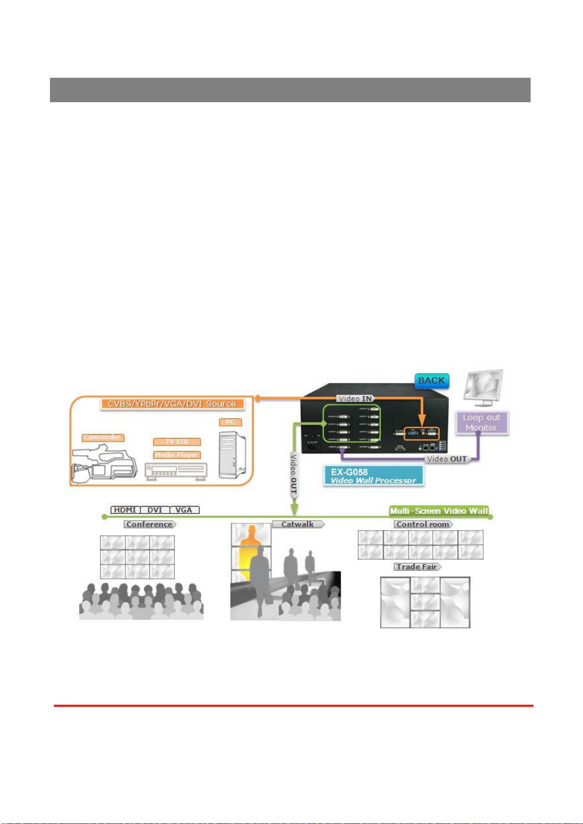
Table 1: I/O Connectors
Input Connector Video Source
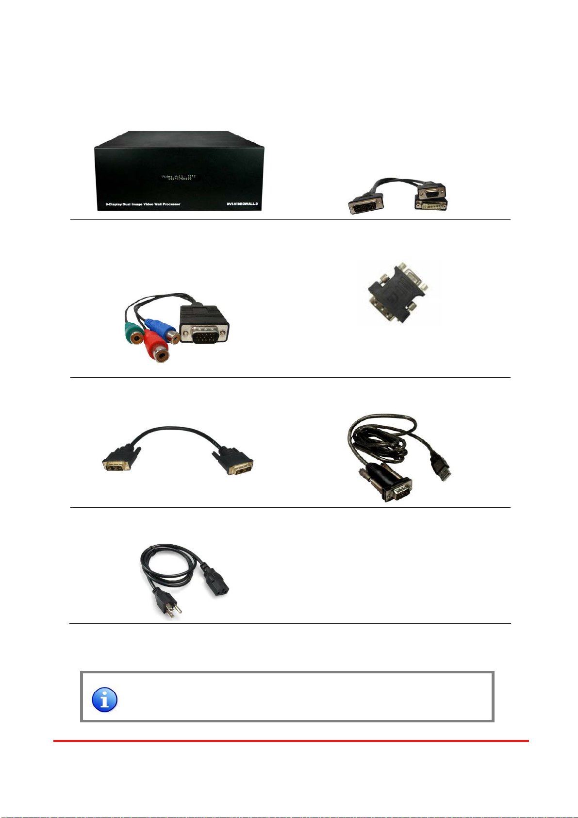
[1] DVI
[2] VGA — with a DVI-to-VGA adapter (DVA01)
[3] Component (YPbPr) — with a DVI-to-VGA adapter (DVA01) and a
VGA-to-component breakout cable (VYPBA01)
[4] 1x DVI + 1x VGA — with a DVI-to-DVI/VGA breakout cable (DDVY01)
DVI-IN
[5] 1x DVI + 1x Component (YPbPr) — with a DVI-to-DVI&VGA breakout cable
(DDVY01) and a VGA-to-component breakout cable (VYPBA01)
VGA [1] VGA — with a VGA cable
Composite [1] CVBS (PAL/NTSC) — with a RCA cable
Bridge Connector 2x DVI* (DVI-CONN)
Output Connector Display
[1] DVI display
[2] VGA display — with a DVI-to-VGA adapter (DVA01)
DVI-I OUT [3] 1x DVI display + 1x VGA display — with a DVI to DVI&VGA breakout cable
(DDVY01)
It is CRITICAL to have the DVI-to-DVI cable connected to the 2 DVI-CONN sockets on
the EX-G058 for normal operation & firmware update. Please have the bridge
connectors linked at any time.
Safety Precautions
I. To prevent fire or shock hazards, do not expose this device to rain or moisture.
II. When connecting other products such as DVD players, and personal computers, you should turn
off the power of this product for protection against electric shocks.
III. The product should be placed more than one foot away from heat sources such as radiators, heat
registers, stoves, and other products (including amplifiers) that produce heat. In addition, do not
cover any material or devices on the top of the device.
IV. Do not use immediately after moving from a low temperature to high temperature, as this causes
condensation,
V. Do not place this product on an unstable cart, stand, or table. The product may fall, causing
serious injury to a child or adult and serious damage to the product.
VI. Unplug this product from the wall outlet before cleaning. Do not use liquid cleaners or aerosol
Hardware Installation
Page 9 of 25

cleaners. Use a damp cloth for cleaning.
VII. Do not allow the same still picture to be projected for a long time or an abnormally bright video
picture to be projected. The video image could be burned in to the display device.
Installation Procedures
Unpacking
Remove the EX-G058 from the shipping container and examine it for any signs of shipping
damage or missing items (check with package contents above). All shipping items should be saved if
the product is to be moved or returned for service. Shipping unit back to dealers for service not in the
original box may result in voiding warranty or additional cost.
Placement
The unit uses convection to cool. A fan is not needed, so do not block the sides of this device or
stack another device on the top or bottom of the EX-G058.
Connections
We recommend the highest quality cables for both input and output connections.
1. Switch off the EX-G058 and all devices that you want to connect.
2. Connect 4 monitors, projectors or other displays that comes with DVI inputs by using male-to-male
DVI cables to EX-G058 DVI outputs.
3. Plug in DVI to DVI/VGA breakout cable (DDVY01) to DVI-IN and plug in VGA to component
breakout cable (VYPBA01) to the VGA connector of the breakout cable.
4. Connect a device equipped with DVI output (such as PC) to the DVI connector of the breakout
cable.
5. Connect a device equipped with component video output (YPbPr such as DVD player or camera)
to the 3-RCA jack of the VYPBA01.
6. Connect a device equipped with VGA output (such as laptop) to the VGA connector of EX-G058.
7. Connect a device equipped with composite video output to composite input of the EX-G058.
8. Connect your computer with the EX-G058 by a 9-pin RS-232 adapter and then install the software.
9. Power up the EX-G058.
10. Switch on all devices connected and then control the display output through RS-232 and software.
Page 10 of 25

Figure 3: Connection Diagram
Componentvideo
YPbPr
DVIorVGA
V
GA
Compositevideo
CVBS
Softwarecontrol
ThruRS-232
V
ideoWall(square)
DVILoop-out
V
ideoWall(arch)
OR
Mustbeconnected
in
betweenallthetime
Page 11 of 25

It is CRITICAL to have the DVI-to-DVI cable connected to the 2 DVI-CONN sockets on
the EX-G058 for normal operation & firmware update. Please have the bridge
connectors linked at any time.
System Requirement and Precautions
1. The EX-G058 provides a software control program which runs under Microsoft Windows 98, 2000,
XP through the interface of RS-232 serial control.
2. Before you click on the icon of the software, make sure you have secured the connection between
your computer COM port and the EX-G058.
3. The EX-G058 provides software control. To make sure all information shown in the software is
synchronized with those in the device, please click “Connect” to acquire the latest data from the
EX-G058 after you press any key on the remote control.
Instruction of Software Connection
1. Power up the EX-G058 and you can see Vacuum Fluorescent Display (VFD) on the front panel
blinks. Make sure the serial port (RS-232 or RS-485) connection is secured.
2. The first step after running the software is to automatically detect if the device responses correctly
through RS-232 port. The process takes 5-15 seconds. If the response is not accurate, a warning
window will show up as the figure below.
The possible reasons causing this failure could be:
zThe EX-G058 is not supplied with power or the EX-G058 enters deep sleep state. Please check
the current status, and reboot the EX-G058.
zThe serial connection through RS-232 is not well established or some other software has taken
the available serial ports. Please make sure the RS-232 cable is well connected and the available
serial port is free to be used by the EX-G058.
Operation Software
Page 12 of 25

3. If the serial connection is well established, you can see similar work window as below.
4. While you move the mouse’s cursor near the borders, in either red or blue, the icon of the cursor
will change as the figure below.
Instruction of Software Operation
File
a. Connect: This will synchronize the status of the EX-G058 with
that of the software, especially after IR commands sent.
b. Save Setting: This will save current user preferred settings
such as the positions and sizes of the videos, the width or color
of border etc. into your favorite setting files.
c. Load Setting: The function will load the favorite settings from
the previously saved file.
d. IR Control: This function is not applicable for EX-G058.
Page 13of 25

e. Auto Sleep: This decides if the EX-G058 enters the deep sleep mode if the video signal cannot be
detected in the main channel.
f. Device ID: This is for identifying the EX-G058 while multiple devices are cascaded by RS-232
over CAT5 module.
g. Factory Reset: This will restore all the system values back to the factory default.
h. Exit: Quit the software.
Background
a. Resolution: Change the output resolution.
b. Layout: The preset layout for main & sub channels.
c. HFlip: Horizontally flip the output video.
d. VFlip: Vertically flip the output video.
e. SWAP: Swap the main and sub channel.
f. Color: The background color selection.
Main
a. Input Source: Select a video/graphic input of the main
channel.
b. Visible: Display the main channel or not.
c. Border: Display the main channel’s border.
d. Label: Display the main channel’s label. Users can define
the content of the label.
e. Layer: This will make the main channel overlays the sub
channel.
f. Pause: Freeze the display of the main channel.
g. Full Screen: Display the main channel full screen.
h. Color Balance: Automatically do the color balance while the main channel’s input is from
VGA/component.
1. Assign an ID for the connected EX-G058: type a number in the “ID
Number” of the device ID setting area and then click “Write”.
2. Read the ID of the connected EX-G058: click “Read” and the ID will
show up.
3. Super Control: all devices cascaded will receive and respond the
same way when you are operating the control software.
4. Single Device Control: remove the check beside the “Super
Control” and type a number that represent a specific EX-G058 and
then click “Apply”. Exit the “Device ID Setting” and click
“Connect”.
Page 14 of 25

i. Auto Config.: Automatically do the auto adjustment while the main channel’s input is from
VGA/component.
Sub
a. Input Source: Select a video/graphic input of the sub-channel.
b. Visible: Display the sub-channel or not.
c. Border: Display the sub-channel’s border.
d. Label: Display the sub-channel’s label. Users can define the
content of the label.
e. Layer: This will make the sub-channel overlays the main channel.
f. Pause: Freeze the display of the sub channel.
Control- Setting Dialog
Border
Select main or sub channel for further setting.
“Clear All” Button: Clear all OSD items.
“Apply” Button: Apply the setting.
1. Border Color: Setup border’s color
by clicking on “Color setting”.
2. Border Width: Input border’s width.
3. Border Type: The placement of border has three types: Option Inside means the added border is
fully inside the video. Option Outside means the added border is completely outside the video and
this added border can overlay the other video input. Option Middle simply adds the border half
inside the video and half outside the video.
4. Text Color: Select the color of the label by clicking on “Color
Setting” button.
5. Text Auto: While selecting “Text Auto”, the label on the screen for
each channel will display its corresponding input channel type.
While unselecting “Text Auto”, users can input the desired string to
be displayed.
Only 15 English characters can be displayed at most.
Page 15 of 25

6. Duty Cycle: The duty cycle of blinking of OSD borders and labels.
7. Frequency: How fast the blink.
Image
1. Choose the scaling type for the main channel at full screen
display.
2. While Blend is selected, users can use the slider to control the
degree of blending.
There is a short period of slight blinking while the EX-G058
processes the blending of the two input videos.
Color
1. Select the main or sub channels.
2. Reset: Restore all the setting on this page back to their default
values.
Page 16 of 25

Zoom
A. Select the main or sub channel.
B. Default: Restore the selected channel without zoom effect.
A. This slider controls the ratio of Zoom.
B. The workplace for controlling the displayed area after zooming the
selected video.
Pattern
1. While “Pattern Model” is chosen, the output will display the selected
pattern. While unselecting this item, the output display works
normally.
2. The orange border indicates which pattern is currently selected.
Users can choose one of the provided patterns by moving cursor
and clicking at the desired one.
A B
A
B
Page 17 of 25

Define the pattern’s color by clicking at the rectangle inside the ellipse,
and then use the sliders for choosing R, G, B depths.
HS / VS Delay
1. Select the main or sub channel.
2. The fine movement of the selected channel.
EDID Code
1. Save: Save the read back EDID Content in PC.
2. Setting: Automatically setup the output resolution according to the
content of EDID.
This setting is according to the content of EDID, and the
optimum resolution for the monitor might be different
because of the limited information of the acquired EDID info.
Control- Display Layout
Page 18 of 25

Output Resolution
Users can define the resolution of the output video to displays. Notice that the connected displays
are with the same resolution.
X Total & Y Total
Define the fineness of the display area. X or Y total can be up to 255.
YTotal
XTotal
Page 19 of 25

X Start, X End, Y Start, Y End
For each display, users can define which section in the resulting mixed video should be displayed.
After setup the X Total and Y Total, users need to define the upper-left (X Start, Y Start) and
bottom-right (X End, Y End) corners for each display. The area to be displayed by default is quad view
as shown.
To activate the new settings for each display, please click the “Window x” button under
“Update Parameters” section on the left of the control interface.
Enable All, Disable All, Default Layout
Clicking on “Disable all” button will make all the connected monitors have an identical display, i.e.,
the output from the front end mixer. “Default Layout” will replace the current display layout with the
default quad view layout. “EnableAll” button updates the connected display with the setup parameters.
In “Temperature Type”, there are two types of temperature representation, Celsius and Fahrenheit,
for the VFD display.
Page 20 of 25
Table of contents
Other Meicheng Media Converter manuals