Meijer 88 5531 41 User manual

88 5531
41
Bedford
Drawer
Chest
(Ebony Finish)
IMPORTANT
NO'TE
Carefully
remove
all
the
parts
from
the
carton
and
put
them
individually
on
asoft
cloth
to
prevent
scratches
or
other
damages
occuring
to
the
wood
parts.
We
have
taken
great
care
in
the
design
of
this
product
and
request
that
you
carefully
and
strictly
follow
our
assembly
instructions
to
ensure
a
completed
product
as
it
was
designed.
Casual Attire
For
Today's Home
Part
List
L.
KD
Drawer
3
pes.
B.
Side
Panel
1
pc.
(Knock-Down
Construction,
please
refer
to
the
last
pages
of
instructions
for
steps
to
complete
drawer
assembly)
Hardware
List
~
~
r
~
Cam
Lock
lcnw
Cam
Lack
1114"
Fill Hud
ac-
314"
Fill liNd
lcnw
12
pes.
(+1
lldni)
12
pes.
(+1
lldni)
44
pes.
(+1
lldni)
24
pes.
(+1
ex1ra)
~
~
@)
CY
MlchlneScnw
An
char
Fill-
Llr1ll
Pllllllncll
9pc:s.
1pc.(+181dra)
2pcs.(+18ldrl)
&pes.
Tools
Required
For
Assembly:
Phillips
screwdriver
Side
Panel
1
pc.
~
1114"
Raund
liNd
lcnw
7
pes.
(+1
lldni)
\))
1111111
Pull
Hindle
3
pes.
K.
KD
Drawer
1
pc.
(Knock-Down
Construction,
please
refer
to
the
last
pages
of
instructions
for
steps
to
complete
drawer
assembly)
~
~
1"
Raund
liNd
lcnw
511"
Raund
HHd
ac-
6
pes.
(+18ldni)
13
pes.
(+1
exira)
~
~
Wooden
DoWII
npplng
RMirllnt
8
pes.
(+1
exlnl)
1pc.
Home Styles ConsumerAssistance
Line
888-680-7460
and
877-831-0319
CH.
1711/09/01
Meijer.com
Assembly Instructions 2/8
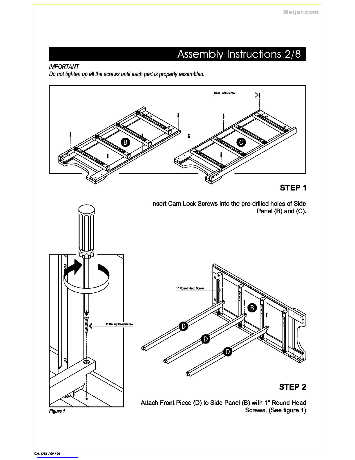
IMPORTANT
Do
not
tighten
up
all
the
screws
until
each
part
is
properly
assembled.
Figure
1
CH.
1711/09/01
Cam
Lock
Screw
)'
STEP 1
Insert Cam Lock Screws into the pre-drilled holes
of
Side
Panel (B) and (C).
1"
Round
Held
Screw
STEP2
Attach Front Piece (D) to Side Panel (B) with 1" Round Head
Screws. (See figure 1)
Meijer.com
Assembly Instructions 3/8
Figure2
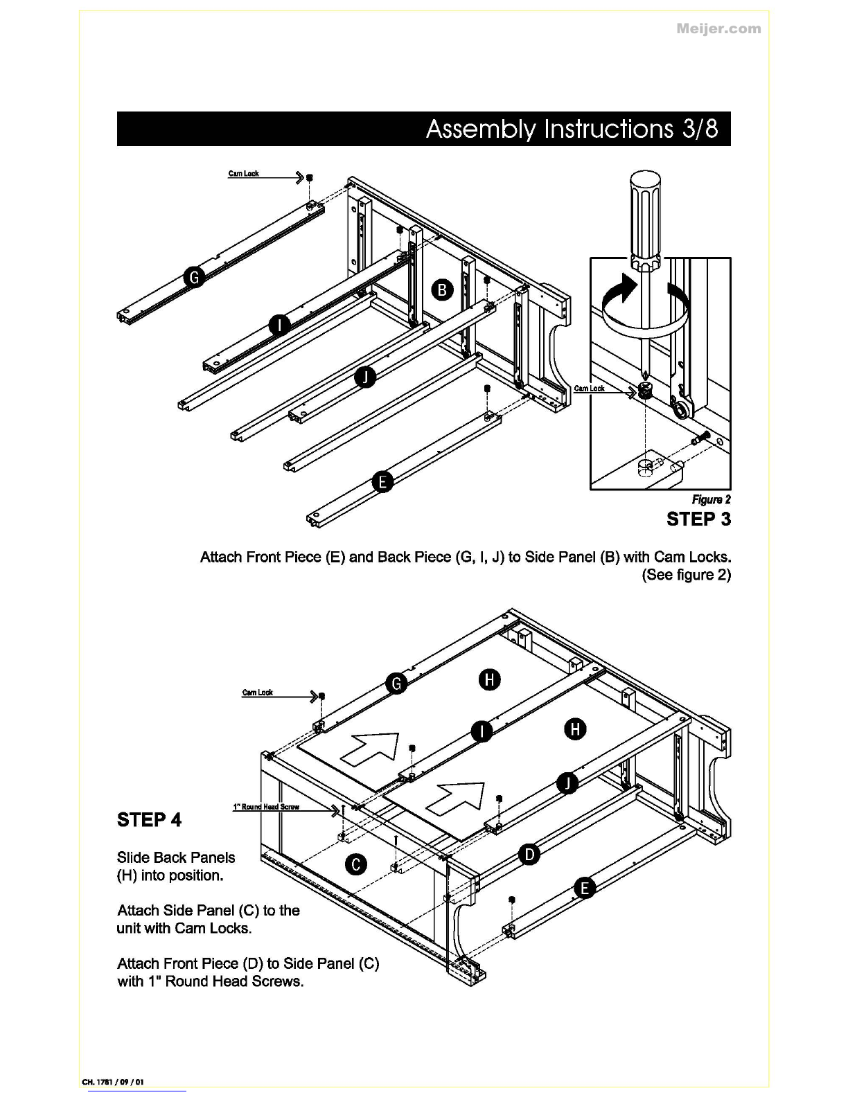
STEP3
Attach Front Piece (E) and Back Piece (G,
I,
J)
to Side Panel (B) with Cam Locks.
(See figure 2)
STEP4
Slide Back Panels
(H) into position.
Attach Side Panel (C) to the
unitwith Cam Locks.
Attach Front Piece (D) to Side Panel (C)
with 1
11
Round Head Screws.
CH.
1711/09/01
Meijer.com
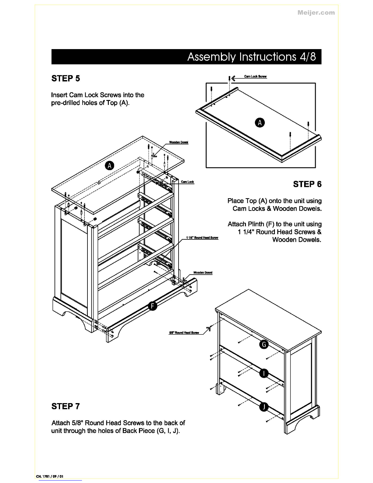
STEPS
Insert Cam LockScrews into the
pre-drilled holes
of
Top (A).
STEP7
Attach 5/8
..
Round Head Screws to the back
of
unit through the holes
of
Back Piece (G,
I,
J).
CH.
1711/09/01
Assembly Instructions 4/8
1114"
Round
Hem!
Screw
CllllllackScmr
STEP&
Place Top (A) onto the unit using
Cam Locks & Wooden Dowels.
Attach Plinth (F) to the unit using
1 1/4
..
Round Head Screws &
Wooden Dowels.
Meijer.com
Assembly Instructions 5/8
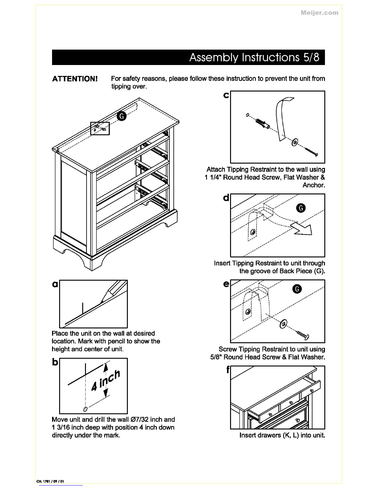
ATTENTION! Forsafety reasons, please follow these instruction
to
prevent the unit from
tipping over.
a
Place the uniton the wall
at
desired
location. Markwith pencil to show the
heightand center
of
unit.
Move unitand drill the
wall07/32
inch and
1 3/16 inch deep with position 4 inch down
directly underthe mark.
CH.
1711/09/01
c
Attach Tipping Restraint to the wall using
1 1/4" Round Head Screw, FlatWasher &
Anchor.
Insert Tipping Restraintto unit through
the groove
of
Back Piece (G).
ScrewTipping Restraint to unit using
5/8" Round Head Screw& Flat Washer.
Insertdrawers (K, L) into unit.
Meijer.com
Assembly Instructions 6/8
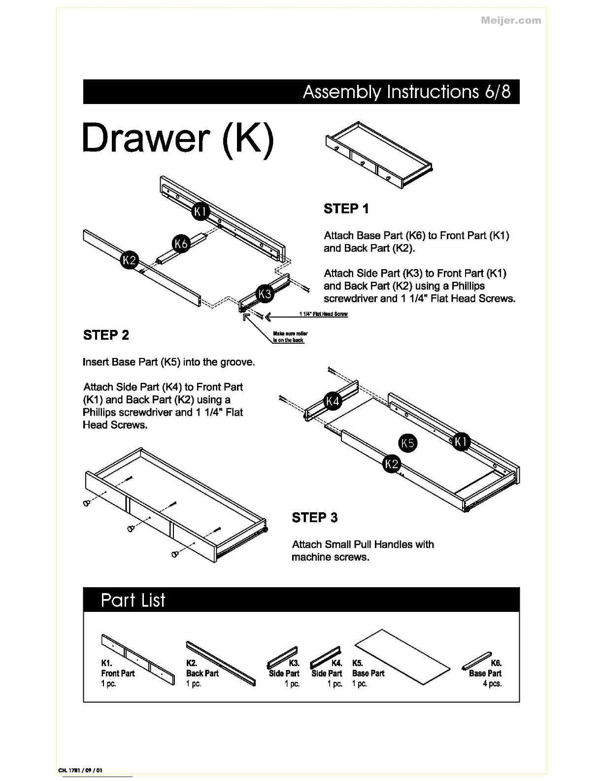
Drawer (K)
STEP2
Insert Base Part (K5) into the groove.
Attach Side Part (K4) to Front Part
(K1) and Back Part (K2) using a
Phillips screwdriver and 1 1/4
11
Flat
Head Screws.
Part
List
CH.
1711/09/01
STEP1
Attach Base Part (K6) to Front Part (K1)
and Back Part (K2).
Attach Side Part (K3) to Front Part (K1)
and Back Part (K2) using a Phillips
screwdriver and 1 1/4
11
Flat Head Screws.
STEP3
Attach Small Pull Handles with
machine screws.
A.A.Ks.
Side
Part
Side
Part
Base
Part
1
pc.
1
pc.
1
pc.
/K&.
Base
Part
4
pes.
Meijer.com
Assembly Instructions
7/8
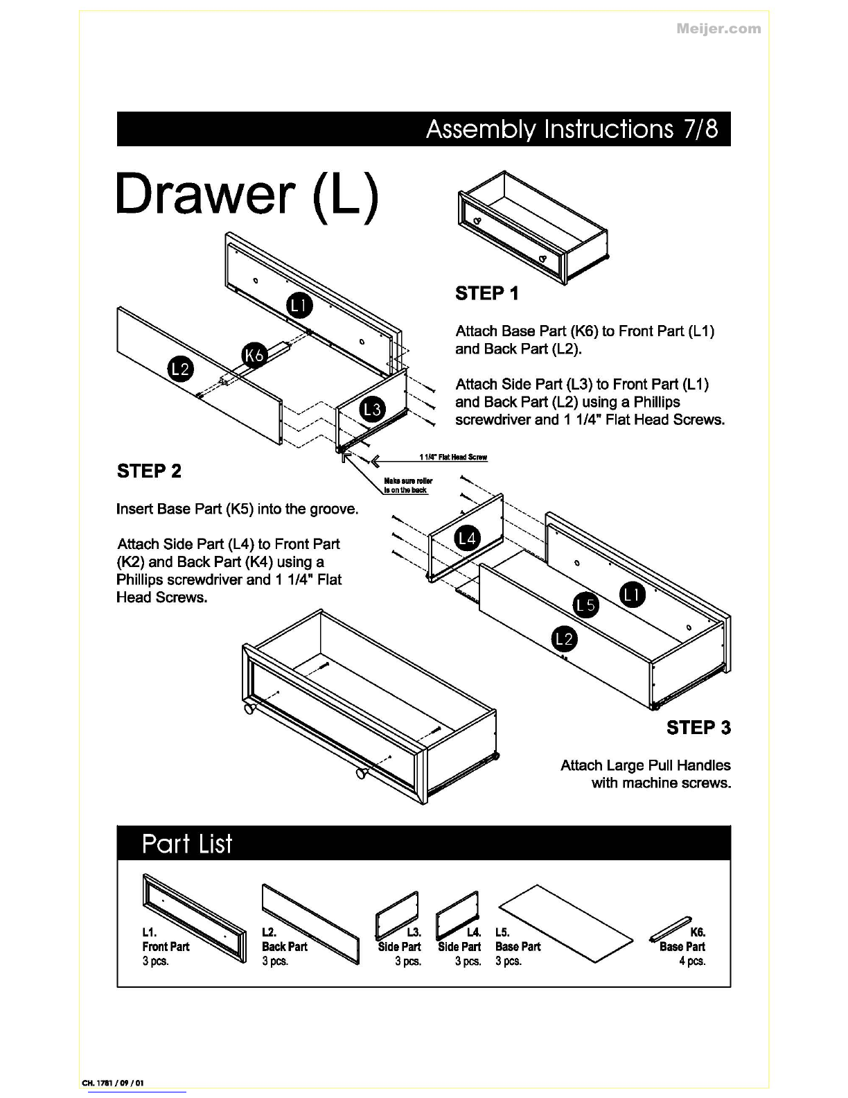
Drawer (L)
STEP2
Insert Base Part (K5) into the groove.
Attach Side Part (L4) to Front Part
(K2) and Back Part (K4) using a
Phillips screwdriver and 1 1/4
11
Flat
Head Screws.
Part
List
L1.
Front
Part
3
pes.
CH.
1711/09/01
STEP1
Attach Base Part (K6) to Front Part (L1)
and Back Part (L2).
',,........,
Attach Side Part (L3) to Front Part (L1)
',,........,
and Back Part (L2) using a Phillips
,,........,
screwdriver and 1 1/4
11
Flat Head Screws.
1114"
Flat
lllld
Screw
'
...............
'
',
'
..................
....................
a.
a.~.
Side
Part
Side
Part
Base
Part
3
pes.
3
pes.
3
pes.
STEP3
Attach Large Pull Handles
with machine screws.
/K&.
Base
Part
4
pes.
Meijer.com
o
II
o
II
0
II
o 0 I
ll
0 0 l
If
o 0 I
u
\_j
II
.....
....,
1/
a~
I
I'
'o
' '
~
,
"
If
" "
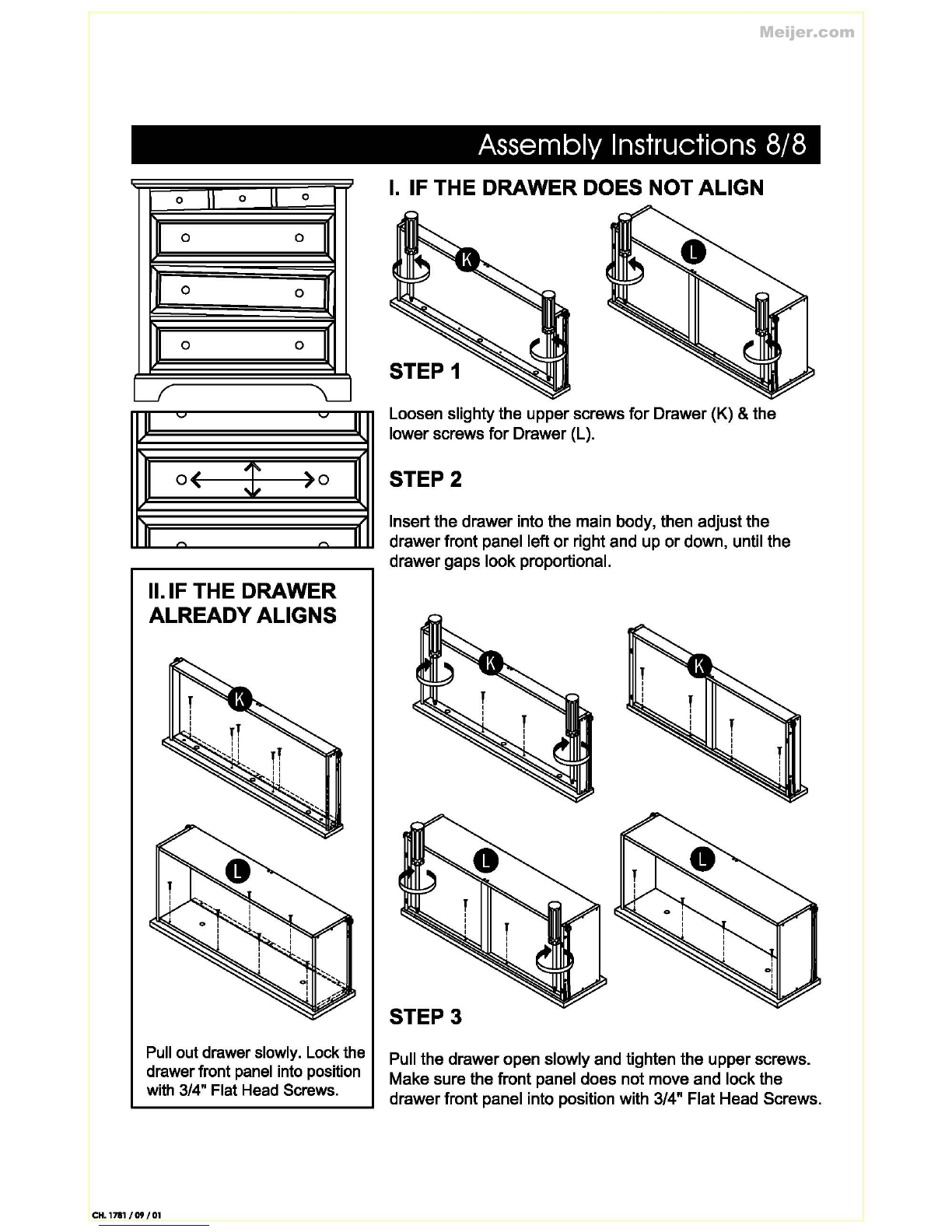
II.IF THE DRAWER
ALREADYALIGNS
II
II
Pull out drawerslowly. Lock the
drawerfront panel into position
with 3/4" Flat Head Screws.
CH.
1711/09/01
Assembly Instructions 8/8
I.
IF THE DRAWER DOES NOT ALIGN
STEP 1
Loosen slighty the upperscrews
for
Drawer (K) & the
lowerscrews
for
Drawer (L).
STEP2
Insert the drawer into the main body, then adjust the
drawerfront panel left
or
right and up
or
down, until the
drawer gaps look proportional.
STEP3
Pull the draweropen slowly and tighten the upper screws.
Make sure the front panel does not move and lock the
drawerfront panel into position with 3/4
..
Flat Head Screws.
Meijer.com
Popular LCD Drawer manuals by other brands


Acnodes
Acnodes MKD6219 user manual

Acnodes
Acnodes KD 81916 Specifications

Network Technologies
Network Technologies RACKMUX-V15-4USB Installation and operation manual

Zline
Zline Attainable Luxury 24" Installation guide and user's manual

Fisher & Paykel
Fisher & Paykel MINIMAL VB60SDEB1 installation guide

Rev-A-Shelf
Rev-A-Shelf 4WTCD-343FLSC installation instructions


