Meiji FINER-CORE-13 User manual
INSTRUCTION MANUAL
FINER CORE
Hand Spray Gun
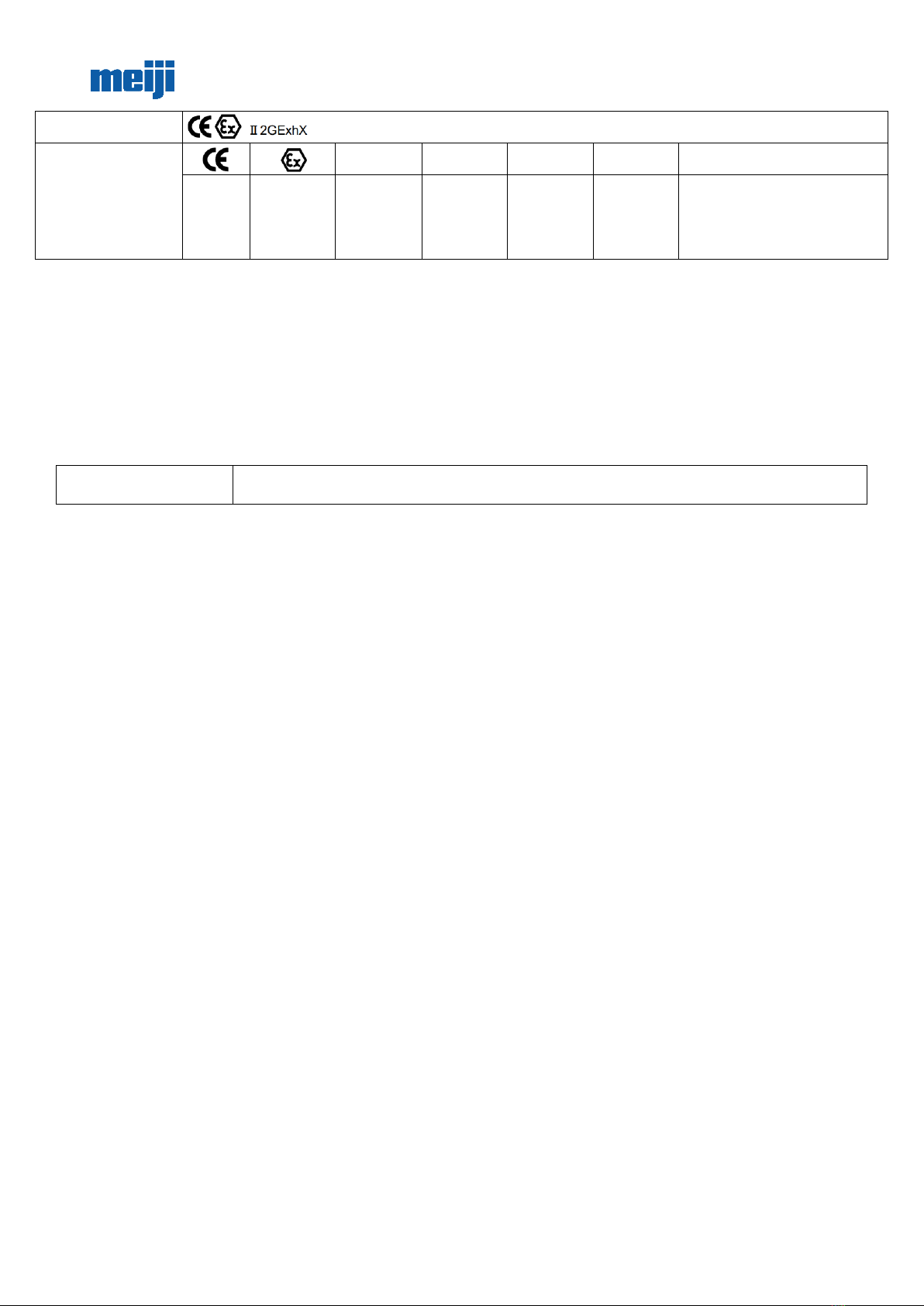
Symbol Marking on the
Spray Gun:
This MEIJI AIR spray gun
complies with 2014/34/eu
Directive relating to
equipment and protective
systems intended for use in
explosive potentially
atmospheres.
II
2
G
Exh
X
Complies
with
European
Directive
Specific
Marking for
Explosion
Protective
Group II
(Surface)
Category
(Zone 1 & 2)
Type of
Atmosphere
(GAS)
lgnition
Protection
(not applied)
Additional conditions: Any static
Electricity should be discharged and
needs to be diverted to the ground via a
conductive air hose not included.
Thank you for purchasing MEIJI Hand Spray Gun.
Before Using this Product:
−To ensure safe and proper use of this product, be sure to read through this operation manual, and understand the contents of this manual thoroughly before using
the product.
−After reading this operation manual, keep it in place for your quick reference whenever required.
−To lend or transfer this product, attach this operation manual to the product.
−If this operation manual is lost or damaged, immediately order a new one from our authorized dealer or distributor.
−To improve the product quality or performance or to ensure safety, the parts used in the product are subject to change. In this case, note that the description and
some parts in the illustrations may be different from those of the actual product.
−If you have any question or comment about the product, contact the distributor of this product or our authorized dealer or distributor in your district.
WARNING/CAUTION
Indicates a case where failure in observing the advice on proper handling manners, or neglecting
appropriate precautions may result in injury or death, and/or serious damage to the product.
Fire and Explosion
1. Keep fire off your paint spray work area.
−Paint is inflammable, causing fire and explosion. To conduct spray work, select a wide, well-ventilated place.
−Be sure to keep an inflammable object (cigarette, ignition equipment, electric equipment, etc.) off your spray work area.
−To clean spray gun, use a solvent whose flash point is equivalent to, or higher than that of the paint being used. Using a general cleaning solvent causes a fire. Use
a cleaning solvent with 37.8℃or higher flash point.
−Provide a fire extinguisher in your spray work area.
2. Do not use a halogenated hydrocarbon solvent.
−Chemical reaction with the solvent causes spray gun body (aluminum parts) to crack or melt.
−Incompatible solvent: methyl chloride, ethyl chloride, methylene dichloride, ethylene dichloride, carbon tetrachloride, trichloroethylene, 1.1.1 trichloroethane,
etc.
−Before using a special paint or paint thinner, thoroughly check if the material is compatible or not.
3. Connect ground cable.
−Ground spray gun securely. For example, use hose with ground wire.
−If spray gun is not securely grounded, it generates sparks of static electricity, causing a fire and explosion.
Protection of Human Body
1. Ensure thorough ventilation.
−To conduct spray work, be sure to select a well ventilated place with a booth.
−If you conduct spray work in an airtight room or insufficiently ventilated place, you may suffer poisoning caused by organic solvent, or a risk factor of flammability
will increase.
2. Wear appropriate clothes and protective gear.
−During spray and cleaning work, always wear appropriate clothes and protective gear (goggles, G-7-04 mask, and gloves).
−Some kinds of paints cause a hazard, if the paint touches eyes or the skin. Check the paint and solvent being used. During sprayand cleaning work, wear appropriate
clothes and gloves.
3. We recommend users to wear ear plugs for health and safety.
−The product may produce a noise level of 80 dB (A) or higher depending on the use condition or work environment.
4. Take a rest if you get tired during spray work.
−Pulling the trigger many times during long-hours of work may cause tendovaginitis.
Improper Handling of Equipment
1. Do not direct spray gun toward people.
−Never attempt to spray paint toward people or animals.
−Failure to observe this instruction may result in inflammations of eyes and the skin, or other hazard to human body.
2. Use spray gun within the maximum operating pressure.
−Never use spray gun at a pressure higher than the maximum operating pressure (0.69 MPa).
3. During interruption of work, release compressed air.
−Before cleaning, disassembly or maintenance/inspection of spray gun, or during a halt of spray work, be sure to release compressed air from spray gun.
−If compressed air is remaining in spray gun, it may accidentally work, or cleaning solvent may spatter, causing a hazard to human body.
−To release compressed air, stop supplying compressed air, paint and paint thinner to spray gun, and pull trigger lightly.
4. Do not touch the tip of the needle valve and paint nozzle during maintenance.
−The tip of the needle valve and paint nozzle is very sharp and may cause an injury.
Other Precautions
1. Do not modify the product.
−Do not modify spray gun.

−If you modify spray gun, it cannot provide sufficient performance. Also, a failure of the machine may result.
2. Stop other equipment.
−To conduct spray work in an operating area of other equipment (robot, reciprocating equipment, etc.), confirm that the equipment has stopped first.
−If you touch a robot or reciprocating equipment, you may get injury.
3. Do not use spray gun for food and chemicals.
−Do not apply spray gun to food or chemicals.
−Corrosion of paint circuit may result in an accident. Also, mixture of foreign substances may result in health disorder.
4. If an abnormal condition occurs, immediately stop spray gun.
−If you find a problem, immediately stop spray gun, and examine the cause of the problem. Do not use gun until the problem can be solved.
Installation
1. Use clean compressed air.
−Use clean compressed air that has passed through an air dryer or air filter. If contaminated air is used, it results in a failure in spray work.
2. Ensure tight connections.
−When connecting paint cup and air hose to spray gun, tighten them securely by using spanner. If the connection is loose, compressed air, paint and other liquids
may spatter over human body, painted work pieces and peripheral equipment, resulting in damage.
3. Conform to the rated withstand pressure of hose.
−Make sure that the air pressure supplied to air hose does not exceed the rated withstand pressure of hose. Do not use an old or damaged hose.
1. Operating Procedure
1. Mount a paint cup and air hose securely to the spray gun by using a spanner or other tool.
2. Although it varies depending on the paint viscosity, property, and operating conditions, a recommended spraying pressure is between 0.15 to 0.25 MPa. Never
use spray gun at a pressure higher than the maximum operating pressure (0.69 MPa).
3. Recommended spraying distance is 150 to 250 mm. If spray gun is too close to a target work piece or it swings like an arc, good finished quality cannot be obtained.
4. To obtain a uniformly finished condition, always hold spray gun at a right angle to the spraying surface.
5. Tightening the air volume adjusting screw clockwise will decrease the air volume, and loosening the air volume adjusting screw counterclockwise will increase
the air volume.
6. If you tighten the pattern adjusting screw by turning it clockwise completely, paint is sprayed in a spot pattern. As you loosen the pattern adjusting screw by
turning it counterclockwise, spray pattern area gradually increases. When you rotate the screw approximately three times, the pattern area becomes the
maximum. Adjust the spray pattern depending on the spray work step and the type of paint being used.
7. If you tighten the paint adjusting screw by turning it clockwise, spray volume decreases. As you loosen the screw by turning it counterclockwise, spray volume
gradually increases. When you rotate the screw three to four times, spray volume becomes the maximum. Set paint volume depending on spray work
conditions.
Pattern adjusting screw
Paint adjusting screw
Clockwise (Spot
pattern)
Counterclockwise (Flat
pattern)
Air volume
adjusting screw
Counterclock wise
Clockwise
Rotation direction of paint adjusting screw
Max. Mín.
Rotation direction of
pattern adjusting screw
2. Maintenance and Inspection
1. Clean and lubricate spray gun everyday to maintain it in the best operating condition.
2. To clean spray gun body, wipe dust off body with a cloth damped with a solvent. If spray gun is soaked in a solvent, lubricant is removed, and an adhering substance
enters air circuit, causing a trouble in spay work.
We shall not be liable for any trouble resulting from use of gun cleaner that causes dust or paint waste to enter paint nozzle air circuit.
3. After using spray gun, be sure to clean spray gun with a clean solvent, and leave cup empty.
4. To clean cup, remove surplus paint from cup first, and then pour an appropriate solvent into cup, to wash off residual paint completely.
5. If spray gun is used with a cleaning solvent remaining in gun and cup, and with paint waste or dust adhering to paint circuit, it causes a failure in spray work.
6. After disassembling air cap (3) and fluid nozzle (2), clean them with a brush. When disassembling fluid nozzle (2), be careful not to damage it.
7. To clean paint circuit, spray a small quantity of solvent as in the same manner as spray work.
8. Be sure not to damage each hole of air cap (3), and center hole and tip periphery of fluid nozzle (2).
9. If needle valve set (6) or air valve (26) malfunctions, apply a small quantity of oil (non-silicone oil) to sliding part from the outside.
10. After cleaning the equipment with water, be sure to eliminate water. Residual water causes the equipment to rust away.
11. Soaking whole spray gun in solvent may cause spray gun malfunction. Also soaking air cap assy. itself for extended period may cause a defective spray pattern.
3. Specifications
Model
Paint feed system
Paint
nozzle
bore
(mm)
Applicable air
cap
Spraying
distance
(mm)
Spraying air
pressure (mPa)
Air
consumption
(L/min)
Paint spraying
volume
(mL/min)
Maximum
effective
pattern
width (mm)
Connection
diameter
Weight
(g)
FINER-CORE-13
Gravity
1.3
FINER CORE
200
0.20
300
170
280
G1/4 (air)
G3/8 (paint)
340
FINER-CORE-15
1.5
200
300
FINER-CORE-
HVLP-13
1.3
FINER CORE
HVLP
0.18 (0.07)
380
135
280
FINER-CORE-
HVLP-15
1.5
155
300
* The paint viscosity values are equivalent to 20 seconds for the lacquer enamel paint using Meiji V-1 viscosity cup.
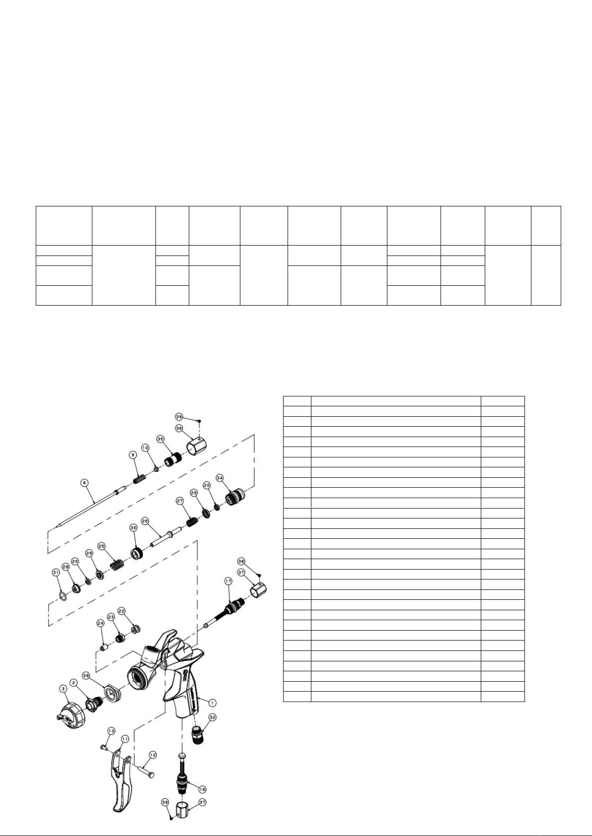
4. Parts List
N.
Name
Qnt.
1
Body
1
2
Paint nozzle
1
3
Air cap set
1
6
Needle valve ass'y
1
9
Needle Spring
1
10
Spring insert
1
11
Trigger
1
12
Trigger pin
1
13
Trigger screw
1
16
Air volume adjusting valve ass'y
1
17
Pattern adjusting valve ass'y
1
20
U-packing P5
2
22
Trigger presser
1
23
Needle packing screw
1
24
Sleeve
1
25
Packing presser spring
1
26
Air valve
1
27
Valve spring
1
28
Packing guide
1
29
O-ring presser
2
30
Valve seat
1
31
O-ring S10
1
32
Hexagon nipple 1/4×M11
1
34
Needle cylinder
1
35
Paint adjusting screw
1
36
Paint adjusting screw cover
1
37
Adjusting screw cover
2
38
Hexagon socket set screw
3
39
Head base (with parallel pin)
1

5. Parts Replacement
Before replacing spray gun parts, remove residual paint, and clean spray gun. Then, release air pressure from spray gun, and remove the air hose and paint cup.
To repair spray gun, place it in a clean level place, and wear protective goggles. For parts replacement, use the specified appropriate tools.
−Replacement of paint nozzle and needle valve ass’y (It is recommended that these parts should be simultaneously replaced).
1. Remove paint adjusting screw (35) and needle spring (9), and pull out needle valve ass'y (6) from the spray gun body.
2. Remove air cap set (3).
3. Remove paint nozzle (2) by using a spanner 17 or socket wrench 17.
4. Tighten paint nozzle (2) at a tightening torque of 10 N・m by using a torque wrench.
−Replacement of air volume adjusting valve ass'y and pattern adjusting valve ass'y
1. Before assembling or disassembling air volume adjusting valve ass'y (16) and pattern adjusting valve ass'y (17), turn the knob counterclockwise completely to
loosen it.
−Replacement of valve seat, air valve, valve spring, O-ring presser, and needle cylinder
1. Remove paint adjusting screw (35) and needle spring (9), and pull out needle valve ass'y (6) from the spray gun body.
2. Remove needle cylinder (34) using socket wrench 14.
3. Remove O-ring presser (29), valve spring (27), and air valve (26) from the spray gun body.
4. Remove valve seat (30) by using hexagon wrench 10, so that seat surface on the mounting part will not be damaged.
5. Tighten valve seat (30) by using hexagon wrench 10 until the seat touches the spray gun body. Then, re-tighten the seat lightly.
6. Insert air valve (26) until it reaches the innermost end so as not to damage seat surface. Then, insert valve spring (27) and O-ring presser (29).
7. Tighten needle cylinder (34) using socket wrench 14.
−Replacement of packing presser spring, O-ring presser, packing guide, and O-ring S10 perfluor
1. Following the procedure for “Replacement of valve seat, air valve, valve spring, O-ring presser, and needle cylinder”, remove the relevant parts.
2. Remove packing presser spring (25), O-ring presser (29), packing guide (28), and O-ring S10 (31).
3. If packing guide (28) and O-ring S10 (31) are hard to remove, vibrate spray gun.
4. Insert O-ring S10 (31), packing guide (28), O-ring presser (29), and packing presser spring (25) in this order.
−Replacement of sleeve
1. Remove needle packing screw (23) with spanner 10.
2. Remove sleeve (24).
3. Insert sleeve (24).
4. Tighten needle packing screw (23) with spanner 10.
6. Troubleshooting
Trouble condition
Cause
Corrective Action
Paint breaking
Lack of paint in paint cup.
Refill paint
The paint circuit is clogged.
Clean paint circuit with a solvent.
A screw of the paint circuit connecting part, or paint nozzle (2), is
loose, or the tapered seat is damaged.
Tightening or replacement
Sleeve (24) has been worn out, or the needle packing screw (23) is
loose.
Replace sleeve (24) or re-tighten needle packing screw
(23) securely.
One-sided
pattern
Part of the square hole of air cap (3) has been clogged or
damaged.
Cleaning or replacement.
Paint or dust is adhering to the tip periphery of paint nozzle (2)
Cleaning or replacement.
Crescent
pattern
Part of the square hole of air cap (3) has been clogged or
damaged, or paint or dust is adhering to inside of the center hole,
or the center hole has been damaged
Cleaning or replacement.
Paint or dust is adhering to the tip periphery of paint nozzle (2)
Cleaning or replacement.
Thick in middle
Paint nozzle (2) has been worn out, and nozzle bore diameter
increased.
Replacement.
Spraying air pressure is too low.
Increase spraying air volume and pressure.
Paint viscosity is too high.
Reduce paint viscosity.
Narrow in
middle
Spraying air pressure is too high
Reduce spraying air volume and pressure.
Dust or paint is adhering to the gap between the center hole of air
cap (3) and the periphery of paint nozzle (2).
Cleaning.
Paint leak from needle packing
screw
Needle packing screw (23) is loose.
Adjust needle packing screw (22).
Sleeve (24) has been worn out.
Tighten or replace needle packing.
Liquid leak from the tip of paint
nozzle
Paint nozzle (2) or needle valve ass'y (6) has been worn out or
damaged.
Replacement.
Sleeve (24) or needle valve ass'y (6) is stuck.
Lubrication.
mproper adjustment of needle packing screw (23)
Adjustment.
Head Office 3-14, 2-chome, Tagawa, Yodogawa-ku Osaka 532-0027, Japan
Tel:+81-6-6309-1227 Fax:+81-6-6309-0157
MEIJI AIR COMPRESSOR MFG. CO., LTD

MEIJI AIR COMPRESSOR MFG.CO.,LTD.
3-14,2-chome,Tagawa,Yodogawa-ku,Osaka,532-0027,Japan
Phone : +81-6-6309-1227
Fax : +81-6-6309-0157
E-mail:export1@meijiair.co.jp
URL,:http//www.meijiair.co.jp/
We, MEIJI AIR COMPRESSOR MFG.CO.,LTD. 3-14,2-chome,Tagawa,Yodogawa-ku,Osaka, 532-0027, Japan,
declare, under our sole responsibility, that the product
DECLARATION OF CONFORMITY
model:
Finer-core SPRAY GUN
on which a plate is affixed, stating :
for use in Group Ⅱand Category 2 ;
are in conformity with European ATEX Directive 2014/34/EU Directive relating to equipment and protective
systems intended for use in explosive potentially atmospheres.
Name and position of issuer: Koji Fukuda, Director and Factory Manager
Signature of issuer: Koji Fukuda
Place and date of issue: Osaka, Japan
This is a translation of the CE declaration of conformity issued by MEIJI AIR COMPRESSOR MFG.CO.,LTD.
Other copies are considered not valid.
2020-08-07
II 2G Ex h X
This manual suits for next models
3
Table of contents
Other Meiji Paint Sprayer manuals


