Norvell M1000 User manual
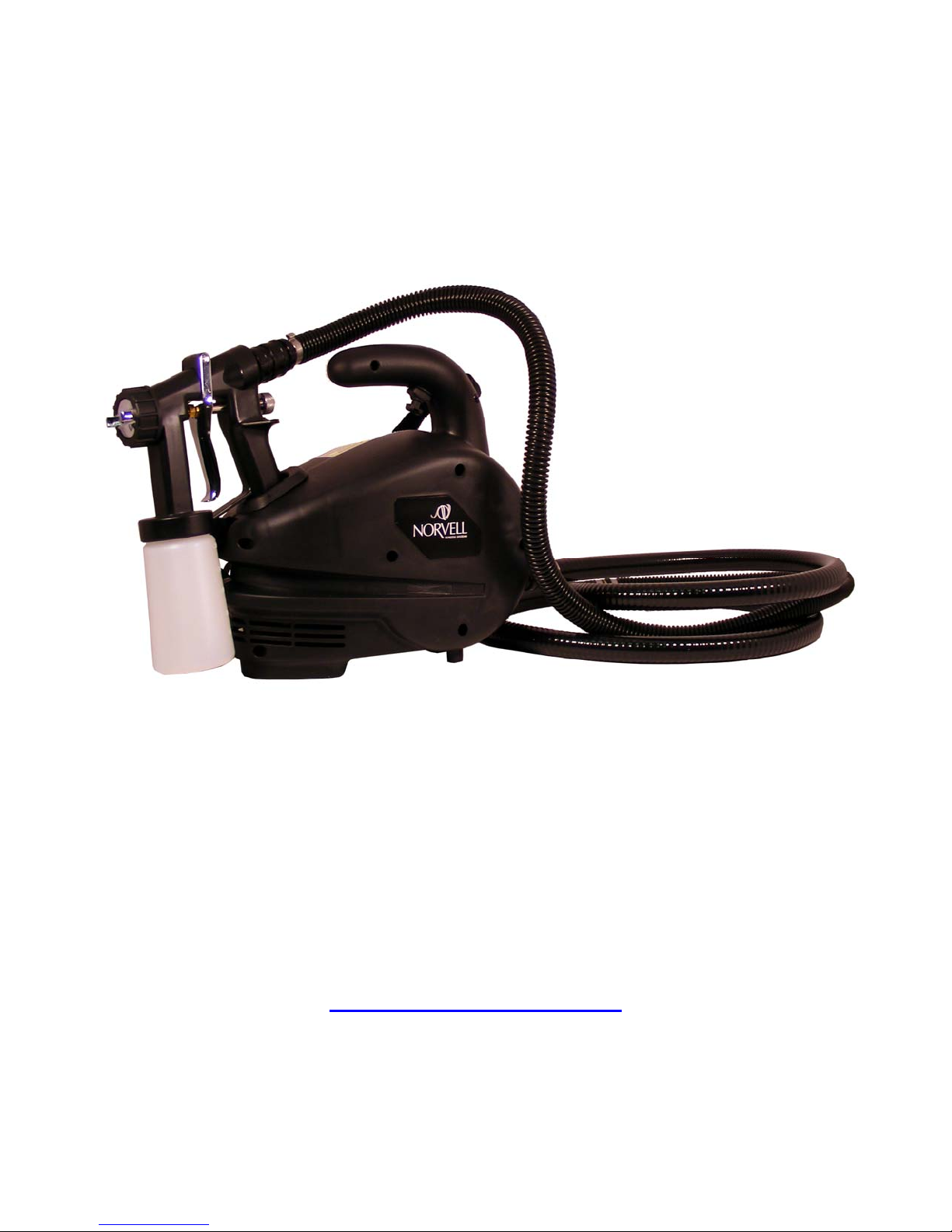
NORVELL SUNLESS SYSTEM
M1000
MOBILE HVLP SYSTEM
INSTRUCTION MANUAL
M1000 HVLP TURBO SYSTEM
(Not Suitable for Continuous Use)
NorvellSunlessSolutions
Customer Service 888-829-2831
www.norvellsunless.com
DO NOT USE EQUIPMENT BEFORE READING THIS MANUAL
This manual contains important warnings and instructions.
Please read these instructions carefully and keep for your reference.

2
Table of Contents
1General Safety Information:.............................................................................................................................pg3
2Set up and operate your M1000 Spray Tan System:.................................................................................pg5
3Prepare the M1000 Spray Gun ........................................................................................................................pg6
4Adjusting the M1000 Spray Gun.....................................................................................................................pg8
5Spraying (Ready to Start and Spray Technique)........................................................................................pg9
6Maintenance (HVLP Machine, Air Hose and Spray Gun)........................................................................pg10
7Troubleshooting ...............................................................................................................................................pg12
Norvell M1000® HVLP Instruction Manual
Congratulations on purchasing the Norvell M1000® tanning system. This product has been specially designed to
provide an efficient application of tanning solution products.
Take a minute to read and understand how to operate your new Norvell M1000® tanning system and you will be able to
provide the perfect tan with every application.
Your M1000 is packaged with the following:
1. M1000 HVLP Turbo powered spray unit.
2. Air Hose
3. M1000 Spray Gun
4. Instruction Manual

1 General Safety Information:
Read all instructions and safety precautions before operating the unit.
3
THIS INDICATES A CONDITION THAT WILL CAUSE SERIOUS INJURY OR LOSS OF
LIFE IF THE WARNING IS IGNORED.
THIS INDICATES A CONDITION THAT COULD CAUSE SERIOUS INJURY OR LOSS OF
LIFE IF THE WARNING IS IGNORED.
THIS INDICATES A CONDITION THAT MAY CAUSE MINOR INJURY AND/OR
EQUIPMENT/PROPERTY DAMAGE.
•Risk of fire or explosion! Solvent and paint fumes can explode or ignite, causing severe
injury and property damage.
•Paints and solvents containing HALOGENATED HYDROCARBONS can react explosively with
aluminum. Always check the product’s label before using these materials in the unit.
•Hazardous vapors: Paint, solvents, insecticides and other materials may be harmful if
inhaled, causing severe nausea, fainting or poisoning.
•Make sure the room is well ventilated. Avoid all ignition sources, such as static electricity
sparks, open flames, hot objects, sparks from connecting and disconnecting power cords, and
working light switches.
•Follow the material and solvent manufacturers’ safety precautions and warnings. Do not use
liquids with flash points less than 100 degrees Fahrenheit (38 degrees Celsius).
•Static electricity can be produced by HVLP spraying. Make sure any electrically conductive object being
sprayed is grounded to prevent static sparking. The sprayer is grounded to prevent static sparking. The M1000
is grounded through the electrical cord on the unit. If an extension cord is necessary, that extension cord must
be a grounded three pronged cord. One that is made for the appropriate voltage used.
•Use a respirator or mask whenever there is a chance that vapors may be inhaled. Read all
instructions with the mask to ensure that the mask will provide the necessary protection
against the inhalation of harmful vapors.
•Do not carry the turbine while spraying.
•Keep the turbine at the maximum distance from the spraying area.
•Tipping the Spray Gun causes the Spray Gun to clog. Dried spray material also clogs the pressure delivery
tube and fittings. The Spray Gun does not function when clogging occurs.
•When not in use, be sure to disconnect the hose and place the Spray Gun into the holder in the turbine to avoid
tipping.
GROUNDING INSTRUCTIONS
This product must be properly grounded. In the event of an electrical short circuit, grounding reduces the risk of electrical
shock by providing an alternate path for the electrical current.
This product is equipped with a cord that has a ground wire and an appropriate ground plug. Plug the unit into an outlet
that is properly installed and grounded in accordance with local codes and ordinances.
4
IMPROPER INSTALLATION OF THE GROUND PLUG CAN RESULT IN THE RIST OF
ELECTRICAL SHOCK. IF REPAIR OR REPLACEMENT OF THE PLUG OR CORD IS
NECESSARY, DO NOT CONNECT THE GROUND WIRE TO EITHER FLAT BLADE TERMINAL.
THE WIRE WITH GREEN INSULATION (WITH OR WITHOUT A YELLOW STRIPE) IS THE
GOUNDING WIRE.
1. For any question regarding proper installation of the ground plug, consult a qualified
(licensed or certified) electrician.
2. Do not modify the plug provided. If the plug does not fit the outlet, have the proper
outlet installed by a qualified electrician.
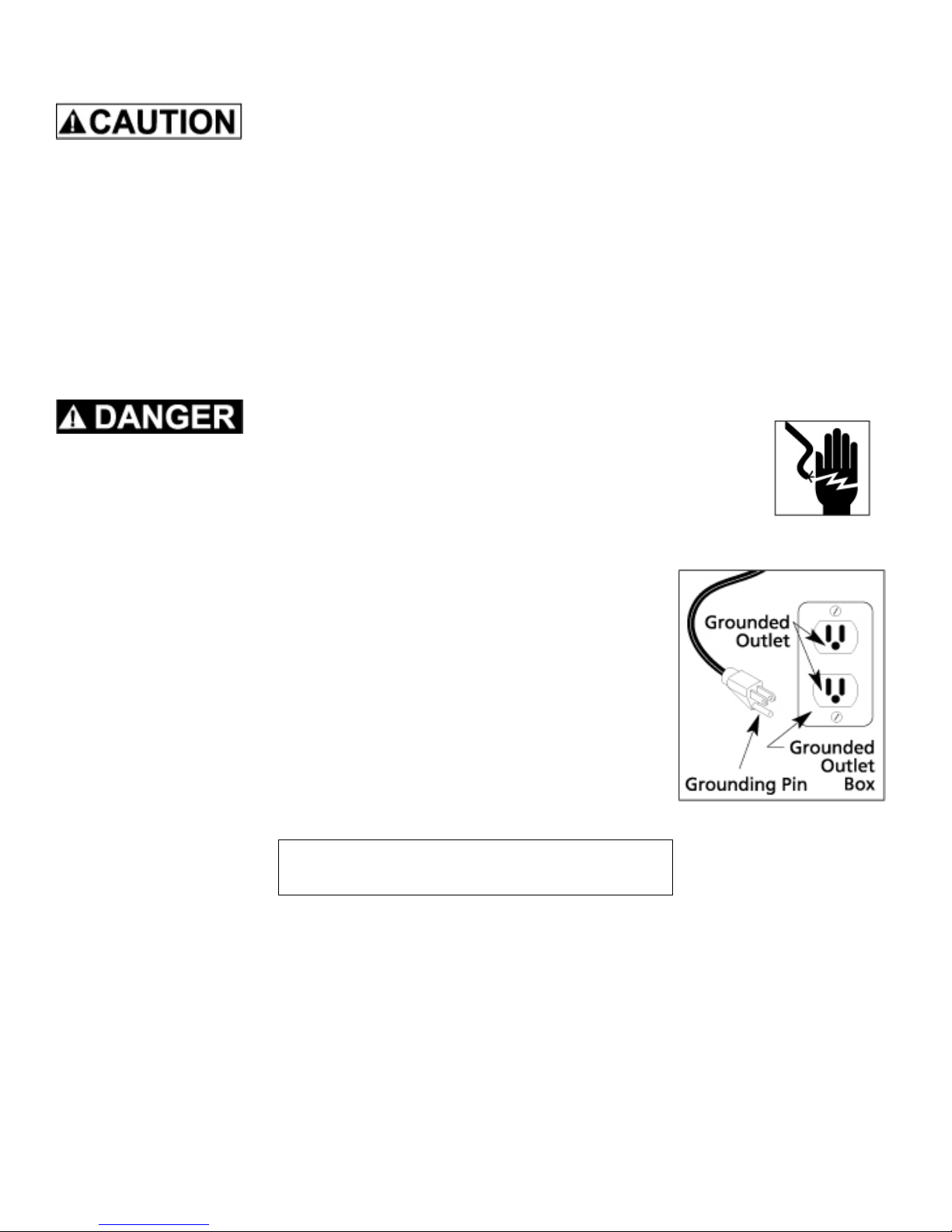
3. This product is for use on a nominal 120-volt circuit and has a grounding plug that
looks like the plug in Figure 2. Make sure that the product is connected to an outlet
having the same configuration as the plug. No adapters should be used with this
product.
4. If an extension cord is required, use only a three wire extension cord that has the
same configuration as the unit cord, including the (round) ground terminal. Make
sure that the extension cord is plugged into a properly grounded receptacle.
5. When using an extension cord, be sure it is in good condition and heavy enough to
meet the specifications in the chart below. If an extension cord is needed the
following wire sizes must be used.
6. (See Chart 1) Figure 2
25’ cord………………………….10, 12, or 14 Gauge
50’ cord………………………………..10 or 12 Gauge
100’ cord………………………………………10 Gauge
Chart 1 Extension Cord Requirements
2 Set up and operate your Norvell M1000® Tanning System:
1. Plug the Norvell M1000HVLP Turbo tanning system unit into a proper electrical outlet. Make sure that the electric
current you are connecting is the same as your unit. (110v or 220v). DO NOT attempt to connect the unit to the
wrong electric current as this will not only damage your unit but also void your warranty.
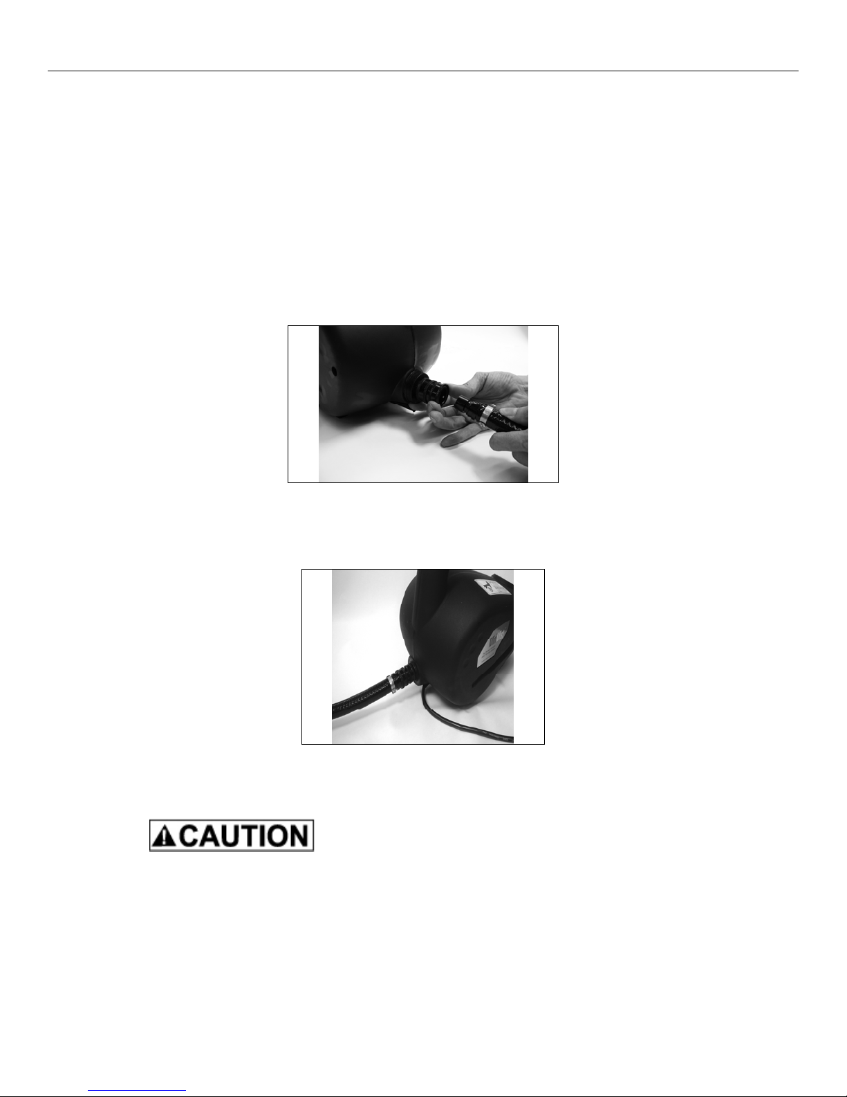
2. Next, locate the male end of the air hose and connect it to the female quick connect on the M1000 tanning
system.
a. To insert the coupler pull back on the ring of the black coupler located on the M1000®system and
connect it to the male connector on the hose. Figure 6.
Fig 6
b. Release the ring to allow the coupler to snap into place. The hose should now be connected to the unit.
Figure 7.
Fig 7
c. To remove the air hose, pull back on the ring of the black coupler and remove.
If you have just finished spraying, the connector may be hot. Allow the M1000 HVLP Turbo unit
to cool down for about 10 minutes before disconnecting the air hose from the HVLP Turbo unit.
Use Caution!
5

3 Prepare the M1000 Spray Gun
1. The M1000 Spray Gun Diagram
Norvell M1000 Mobile Spray
Gun
Parts List and Diagram
Norvell Customer Service
888-829-2831
www.NorvellSunless.com
6

3 Prepare the M1000 Spray Gun Cont’d.
1. Follow the diagram to prepare the Spray Gun
a. Unscrew the plastic cup from the Spray Gun. Pour Norvell sunless tanning solution into the cup. Do not
fill more than ¾ full.
b. Carefully screw the cup back onto the main body of the Spray Gun. Screw the cup on firmly but DO NOT
over tighten. Over tightening will cause the cup to “pop” and damage the threads. Leakage will
require replacement of the cup.
c. Locate the air cap (#2) on the M1000 SPRAY GUN diagram. Slightly turn the air cap ring (#1) anti or
counter clockwise to loosen the air cap. Notice that you can now rotate the air cap freely.
d. Look at Spray Gun Patterns diagram below. Note the position of the air cap and the direction of the spray
pattern. Pattern 1 is for spraying across from side to side. Pattern 2 is for spraying up and down.
Pattern 3 will produce a spot or circle. Patterns 1 and 2 are the most common positions for applying
tanning solutions.
e. Turn the air cap (#2) to the position you want. Turn the air cap ring (#1) clockwise to lock the air cap in
place.
SPRAY GUN PATTERNS
1. Spraying across from side to side
2. Spraying up and down.
3. Spraying in a spot or circle
2. Next, position the M1000 HVLP Turbo Unit as far away as practical and possible from the area where you will
spray.
3. Attach the remaining end of the hose to the M1000 Spray Gun as follows:
d. Locate the coupler at the rear top of the M1000 Spray Gun. See SPRAY GUN diagram.
e. Pull back on the collar of the black connector on the air hose.
f. Push the connector over the coupler and release. Figure 7.
g. Your Spray Gun should now be firmly attached to the air hose.
7

4 Adjusting the Spray Gun
a. Locate the Solution Flow Screw (#10) on the M1000 SPRAY GUN diagram.
b. Turning the Solution Flow Screw clockwise reduces and will eventually stop the flow of solution. DO NOT
over-tighten the screw as this will cause damage to the end of the needle. Once the trigger cannot be
pulled back there is no point in tightening the screw down more, this will only damage the end of the
needle.
c. Turning the Solution Flow Screw anti or counter clockwise will increase the flow of solution.
d. In general, 1 ½ - 2 full turns from the fully closed position will provide a good solution flow. You may find
that you want more or less solution. You can adjust the Solution Flow Screw to your desired setting.
NOTE: Opening the Solution Flow Screw more than 3 turns will not increase the solution flow and will in
fact decrease the efficiency of your Spray Gun
e. In general, hold the M1000 Spray Gun 6” (10cm) from the person being sprayed. Moving the Spray Gun
back will increase the size of the mist pattern. Moving the Spray Gun closer will decrease the size of the
mist pattern. The further away you hold the Spray Gun, the more you will need to increase the solution
flow thus causing abnormal amounts of airborne solution (overspray).
f. Holding the Spray Gun closer to the person being sprayed along with a minimum flow of solution will
provide the best results, no streaks or running solution and virtually no mist in the spray area.
g. Be sure to move the Spray Gun at a slow, steady speed keeping the distance of the Spray Gun the same
throughout the application. This will ensure perfect results. It is actually very easy. Practice a few times
and you will be an expert.
h. It is best to hold the Spray Gun in a vertical position when spraying. If you want to change the direction of
the mist pattern, rotate the position of the air cap rather than turning the Spray Gun on its side.
i. Always hold or store the Spray Gun in a vertical position. A slot in the M1000 HVLP Turbo Unit is
provided to hold and store the Spray Gun. It is a good habit to use it when you are not spraying.
j. Do not over-tighten the solution flow screw (#10) as this will damage the end of the needle point. Tighten
the screw until the needle cannot be pulled back. Once this point is reached there is no point in turning
the solution slow screw anymore as this will only cause damage to the needle point.
8
5 Start Spraying:
a. You are now ready to begin.
b. The ON/OFF Switch is located under the carry handle of the M1000 HVLP Turbo Unit. Turn it on. You
will hear a sound similar to a vacuum cleaner. You may also notice that air is now blowing out of the front
of the Spray Gun. This is correct. Air will continually flow from the air cap of the Spray Gun as long as
the M1000 HVLP Turbo Unit is running and the air hose is connected.
c. Open the Solution Flow Screw as described in item 4.
d. Set the mist pattern you wish to use by adjusting the air cap to the desired position. Refer to Mist Pattern
Diagram
e. Direct the Spray Gun to the area of the body that you want to start spraying.
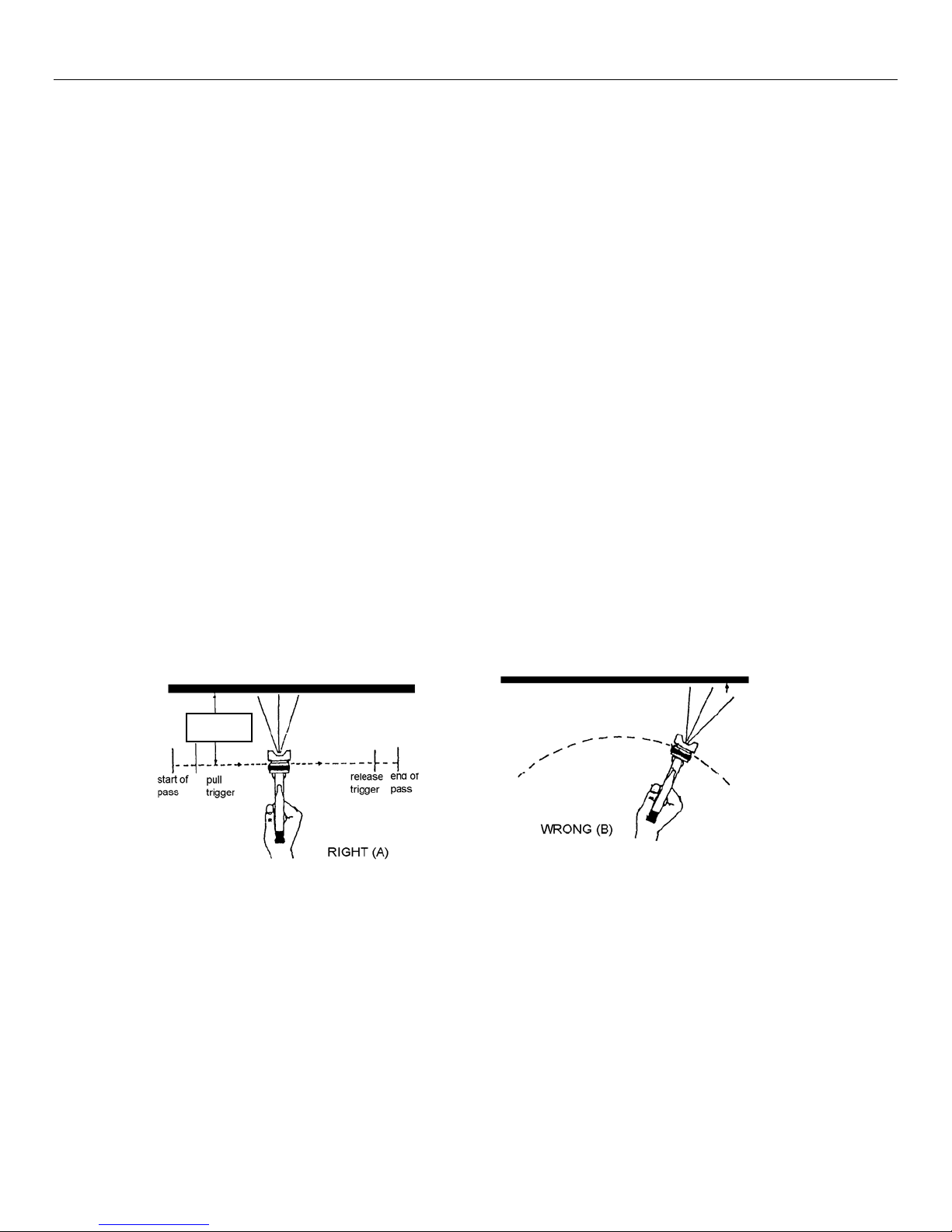
f. Pull back on the trigger (#13) and move the Spray Gun as noted in the diagram below. Do not wave the
Spray Gun back and forth in front of your client by bending your wrist. Rather, keep your wrist straight
and move your entire arm. Movement should be steady, even and deliberate, keeping your distance the
same at all times.
PROPER SPRAYING TECHNIQUE
6IN
9
6 Maintenance
1 Norvell M1000 HVLP Turbo
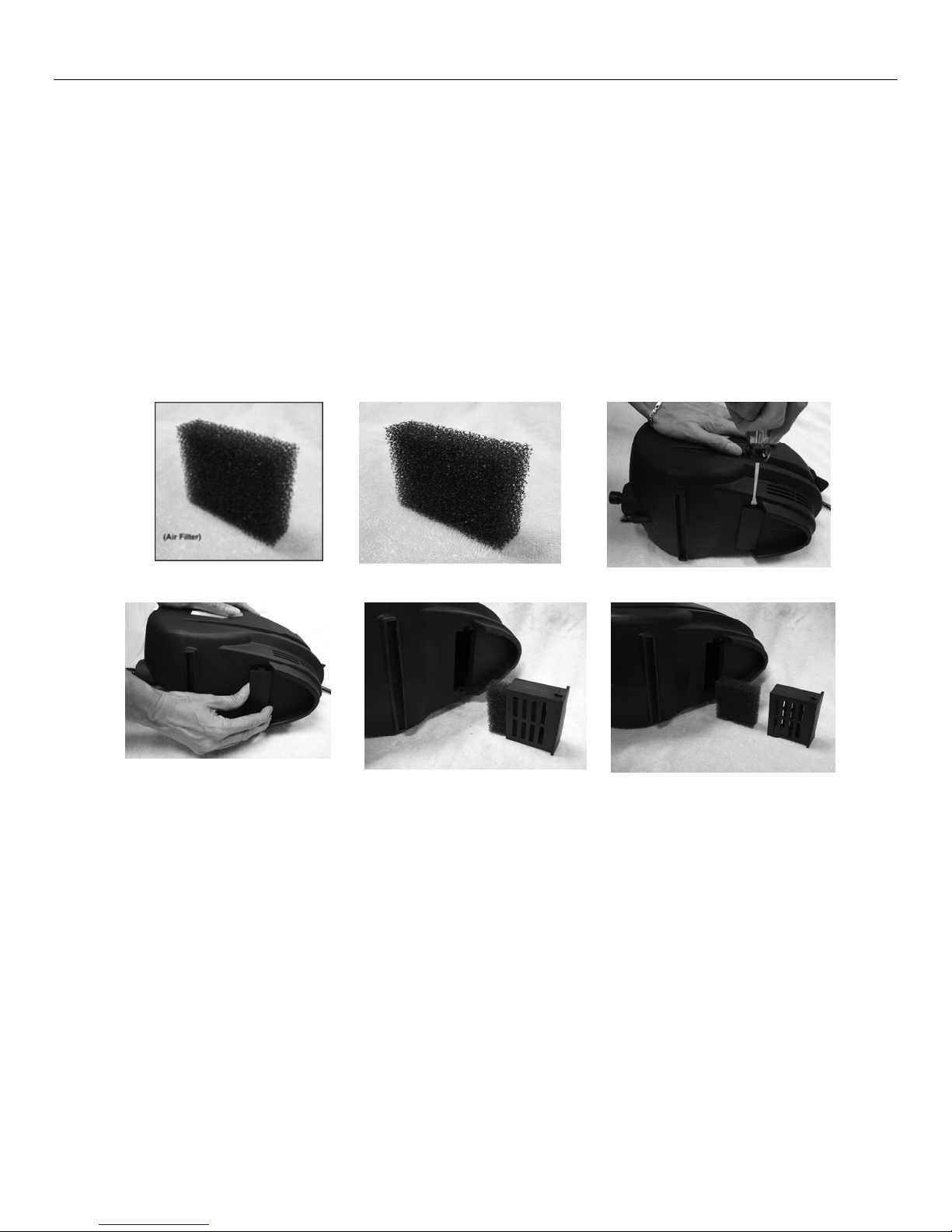
a. The only maintenance necessary on the HVLP Turbo unit is cleaning and/or changing the filter element. The
filter should be removed and rinsed out at least once daily or at least every 4 tanning sessions. The filter
housing and filter are located on the under side of the M1000 HVLP Turbo Unit.
b. To clean the filter, (See Figure 1)
c. Place the M1000 HVLP Turbo unit on one side at a time. Using a small screwdriver insert the blade into the
slot and push down and out at the same time. (See Figure 2-Do this on both sides)
d. Using your thumb and index finger, pull the filter housing out. (See Figure 3)
e. Pull the filter out of the filter housing to clean. (See Figure 4 & 5)
Air Filter Fig 1 Fig 2
Fig 3 Fig 4 Fig 5
2 Air Hose.
a. Wipe the air hose daily with a damp cloth and store in a clean dry place.
3 Spray Gun
a. It is important to clean your Spray Gun daily.
b. At the end of the day or when the equipment will not be used any more, disconnect the Spray Gun from the
air hose.
c. Carefully unscrew the cup. If there is remaining solution, either close the cup with a cup lid, or pour the
remaining solution into a proper storage container.
d. Rinse the cup under warm running water until clean.
10

11
6 Maintenance Cont’d.
e. Fill the cup about ¼ full with water. Reconnect Spray Gun to Air Hose. Turn on the M1000 HVLP Turbo Unit.
Direct the Spray Gun to a safe area and spray the clean warm water through the Spray Gun until the cup is
empty.
f. Turn off the M1000 HVLP Turbo Unit. Disconnect the Spray Gun. Unscrew the cup.
g. Wipe all exposed areas dry.
h. Unscrew and remove the Air Cap Ring (#1). Rinse the threads under warm running water. Wipe, clean the
threads and dry. Add a small amount of Spray Gun lube to the threads.
i. Remove the Air Cap (#2). Rinse under warm running water. Wipe, clean and dry.
j. If necessary, remove Air Distributor Plate (#5). Rinse under warm running water. Wipe clean, dry and
lubricate with Spray Gun lube.
k. Reinstall the three pieces you just removed by reversing the removal procedure. Your Spray Gun should be
ready for the next use. Store the Spray Gun in the holder on the M1000 HVLP Turbo Unit.
l. The Solution nozzle (#3) can be removed for additional cleaning if necessary. Be careful. There is a Solution
nozzle gasket (#4) around the threads of the Solution nozzle. Be sure to reinstall or leakage will occur.
Removal of the Solution nozzle is not necessary on a daily basis. You should however remove it once a
week and rinse under running water. The Solution nozzle can be easily removed with an adjustable wrench
or spanner. Place the tip of your adjustable wrench or spanner on the two flat areas of the nozzle and twist
anti or counter clockwise.
m. The Solution needle (#10) can also be removed for additional maintenance. To remove: Turn the Solution
Flow Screw anti or counter clockwise until it comes out of the Spray Gun. Be careful when removing the
Solution Flow Screw as there is a small spring (#9) around the needle. Do not lose it. This is important to the
operation of the Spray Gun. Set the spring aside and pull the trigger all the way back until you can grab the
needle with your finger tips and pull it out from the back of the Spray Gun. Once removed, rinse under warm
running water, Clean and dry. Reinstall reversing the removal procedure. NOTE: Occasionally it is
necessary to lubricate the needle (#10) where it slides through the gland nut (#7). Simply rub a few drops of
Spray Gun lube around the needle shaft and reinsert into the back of the Spray Gun.

12
7 Troubleshooting
1. M1000 HVLP Turbo unit turned ON. Air blows out of M1000 Spray Gun?
•This is correct. Air blows constantly when HVLP Turbo unit is ON.
2. M1000 HVLP Turbo unit turned ON. Unit does not operate or blow air?
•Check that the unit is plugged in to proper electric source. Be sure there is power at the electric source. If
there is no problem with electric supply, call for technical support.
3. M1000 HVLP Turbo unit is turned ON, the trigger is pulled back on Spray Gun, but no solution comes out?
•Check that the cup is screwed firmly to Spray Gun.
•Check that there is no solution bubbling or leaking around the cup.
•
Turn M1000 HVLP Turbo unit OFF. Unscrew cup. Be sure that Solution Tube and Disc (#14) is connected
and has not come loose. Locate the two small holes in the Disc around the Solution tube
. Be sure that these
two small holes are not clogged with dried solution. To clean, carefully insert a pin through each hole ensuring
that they are clear.
•Turn M1000 HVLP Turbo unit OFF. Remove air cap ring, Remove air cap, Remove Air Distributor Plate.
Remove Solution nozzle (#3) with an adjustable wrench or spanner. There is a Solution nozzle gasket (#4)
on the Solution nozzle. Do not lose it. Rinse Solution Nozzle under running water and check for dried
solution that may have blocked the hole. Reinstall Solution Nozzle Gasket. Reinstall Solution Nozzle, Air
distributor plate, air cap and air cap ring. Try spraying again. If you still have a problem, call for technical
support.
4. Solution leaks in front of trigger.
•With an adjustable wrench or spanner tighten Solution Needle Packing Screw (#7). Do not over tighten. This
can cause Solution needle to stick and not spring back. Try spraying again. If leaking continues the Solution
Needle Packing needs to be replaced. (Rare). Remove Solution Needle Packing Screw (#7). Pry out the
Solution Needle Packings (4). Replace. Reinstall Solution Needle Packing Screw. Tighten all the way, and
then back off slightly. (1/8 turn) Test spray gun for leakage. If you still have a problem call technical support.
5. When M1000 HVLP Turbo unit is ON, Solution continues to spray from Spray Gun without trigger being pulled.
•Immediately turn M1000 HVLP Turbo unit OFF.
•Disconnect spray gun from air hose.
•Slightly adjust (loosen) Solution Needle Packing Screw (#7). Test to see if problem is resolved.
•Check to see that Needle Spring is installed. (#9). Remove Solution Flow Screw (#10). Look for Needle
Spring around the back of the Solution Needle. (See diagram). If lost, call for replacement.
•Check Solution nozzle. Remove and clean following directions 9.c.iv. Above.
6. Solution leaks around the top of the cup.
•Make sure the cup is screwed firmly to the body of the Spray Gun.
•Make sure the threads around the cup are clean and the threads inside the cup top assembly are clean.
•Replace the cup top gasket. Pry out old gasket. Install new gasket. Test spray gun.

13
8 Warranty and Technical Support
For all technical questions please call Norvell Spray Systems at 888-829-2831.
For spraying technique visit www.norvellsunless.com
Technical Support: Available Monday-Friday, 8am-5:00pm, CST.
Norvell Sunless Solutions
888-829-2831
www.Norvellsunless.com
Norvell Spray Systems
One year Limited Warranty
This machine and Equipment is WARRANTED by Norvell Spray Systems for a total period of one year from the
ORIGINAL date of purchase by the ORIGINAL PURCHASER. Proof of purchase should be included and all SHIPPING
CHARGES to be pre-paid.
NORVELL SPRAY SYSTEMS, upon examination of the machine/equipment will replace or repair at their discretion any
defects in material or workmanship.
This WARRANTY does NOT include: miss-use, damage, neglect, alterations, disassembled equipment or modifications,
lack of maintenance, cleaning, water damage to electrical parts and INCORRECT VOLTAGE CONNECTION. This
WARRANTY is in lieu of all other express warranties, any WARRANTY implied by law, including but not limited to implied
warranties of merchantability or fitness, is excluded to the maximum extent permitted by law and, if not excludable, it is
limited to the duration of the express Warranty. No representative or person is authorized to extend this Warranty or to
create for NORVELL SPRAY SYSTEMS, any other liability in connection with the sale of any NORVELL SPRAY
SYSTEMS product. NORVELL SPRAY SYSTEMS shall not be liable for any consequential, incidental, or special
damages of any kind directly or indirectly resulting from breach of any express or implied Warranty. Some States do allow
the exclusion of limitation of incidental or consequential damages or limitations on the length of any Warranty so that the
above limitations and exclusions may not apply to you; however, to the maximum extent permitted under applicable law,
the only rights and remedies shall be to obtain a replacement for any defective product. This Warranty gives you specific
legal rights and you may also have other rights which vary from state to state and country to country.
Other manuals for M1000
1
Table of contents
Other Norvell Paint Sprayer manuals


Popular Paint Sprayer manuals by other brands


Chicago Electric
Chicago Electric 99702 Set up and operating instructions

Graco
Graco 17R236 Operation, parts

Graco
Graco GMAX II 3900 Premium Quick operator's guide

Toro
Toro 41642 installation instructions

WAGNER
WAGNER 2371053 Translation of the original operating instructions

Hardi
Hardi Navigator 550M Operator's manual


