Meinberg microSync 10 Series User manual

MANUAL
microSync
NTP/PTP Time Source
January 19, 2023
Meinberg Funkuhren GmbH & Co. KG


Table of Contents
1 Copyright and Liability Exclusion 1
2 The microSync System 2
2.1 microSync - Brand and Device Type .................................... 2
2.2 Device Manufacturer ............................................. 2
2.3 Target Readership .............................................. 2
2.4 Returning Products .............................................. 3
3 microSync System Description 4
3.1 Device Design, Functions and Area of Application ........................... 4
3.2 System Variants microSync ......................................... 5
3.3 Hardware Specifications ........................................... 8
3.3.1 Chassis Specifications ....................................... 8
3.3.2 Available Power Supplies ..................................... 10
3.3.3 Available Receiver and Oscillator Options ............................ 12
3.3.4 Environment ............................................. 12
3.4 Type Tests / Compatibilities ......................................... 13
3.4.1 Electromagnetic Compatibility - Emission ............................ 13
3.4.2 Electromagnetic Compatibility - Immunity (microSync models 1xx, 2xx, 3xx and 4xx) . . . 14
3.4.3 Electromagnetic Compatibility - Immunity (microSync models 5xx, 6xx, 7xx and 8xx) . . . 15
3.4.4 Safety Tests ............................................. 15
3.4.5 Environmental Tests - microSync models 1xx, 2xx, 3xx and 4xx ................ 16
3.4.6 Environmental Tests - microSync models 5xx, 6xx, 7xx and 8xx ................ 17
3.4.7 Compliance .............................................. 17
4 Important Safety Information 18
4.1 Important Safety Information and Safety Precautions .......................... 18
4.2 Used Symbols ................................................. 19
4.3 Product Documentation ........................................... 20
4.4 Safety During Installation .......................................... 21
4.5 Connection of Protective Earth Conductor/Grounding .......................... 24
4.6 Safety During Operation .......................................... 25
4.7 Safety During Maintenance ......................................... 26
4.8 Handling of Batteries ............................................ 27
4.9 Safety Information for SFP Modules ................................... 28
4.10 Cleaning and Care .............................................. 29
4.11 Prevention of ESD Damage ......................................... 29
4.12 Return of Electrical and Electronic Equipment .............................. 30
5 Before you start 31
5.1 Text and Syntax Conventions ........................................ 31
5.2 Abbreviation List ............................................... 32
5.3 Required Tools ................................................ 33
5.4 Additional Software ............................................. 34
5.5 Preparing Installation ............................................ 35
5.6 Unboxing the Device ............................................. 36
5.7 Disposal of Packaging Materials ...................................... 37
6 System Installation 38
6.1 Connecting the System ........................................... 39
6.2 Initial Network Configuration ........................................ 40
6.2.1 Network Configuration via Serial Connection .......................... 41
6.2.2 Network Configuration via Web Interface ............................ 43
6.2.3 Network Configuration via Meinberg Device Manager ..................... 45
3

6.3 Initial Start of Operation .......................................... 47
6.3.1 Start of Operation with meinbergOS Web Interface ...................... 47
6.3.2 Start of Operation with Meinberg Device Manager Software ................. 48
7 Security Guide 50
7.1 General Overview ............................................... 50
7.2 Securing Management Access ....................................... 52
7.3 User Management .............................................. 55
7.4 Securing the NTP Time Service ...................................... 62
7.5 Event Logs ................................................... 64
7.6 Updating the Firmware and Backing Up the Configuration ....................... 65
8 The meinbergOS Web Interface 67
8.1 Introduction: meinbergOS Web Interface ................................. 67
8.1.1 Terminology of Navigation Elements in the meinbergOS Web Interface ........... 69
8.1.2 Formatting and Structural Principles of this Manual ...................... 70
8.1.3 Basic Configuration Principles ................................... 71
8.2 Header Bar .................................................. 73
8.3 Dashboard ................................................... 75
8.4 Configuration ................................................. 77
8.4.1 Configuration - References ..................................... 78
8.4.2 Configuration - Network ...................................... 82
8.4.3 Configuration - NTP ........................................ 92
8.4.4 Configuration - PTP ........................................ 99
8.4.5 Configuration - IO Ports ...................................... 106
8.4.6 Configuration - Users ........................................ 107
8.5 State ...................................................... 118
8.5.1 State - References .......................................... 119
8.5.2 State - Network ........................................... 126
8.5.3 State - NTP ............................................. 131
8.5.4 State - PTP ............................................. 140
8.5.5 State - IO Ports ........................................... 148
8.5.6 State - Clock Module ........................................ 149
8.5.7 State - Users ............................................. 151
8.6 Maintenance ................................................. 153
8.6.1 Maintenance - Inventory ...................................... 154
8.6.2 Maintenance - System Log ..................................... 163
8.6.3 Maintenance - Kernel Log ..................................... 164
8.6.4 Maintenance - Restart NTP .................................... 165
8.6.5 Maintenance - Reboot Device ................................... 166
8.6.6 Maintenance - Factory Reset ................................... 167
8.6.7 Maintenance - API Reference ................................... 168
8.6.8 Maintenance - SNMP MIBs .................................... 168
9 Configuration and Monitoring with Meinberg Device Manager 169
9.1 Maintenance, Servicing and Repairing .................................. 170
9.1.1 Firmware Updates .......................................... 170
9.1.2 Troubleshooting and Alarming ................................... 171
10 Support Information 173
10.1 Basic Customer Support ........................................... 173
10.2 Support Ticket System ............................................ 174
10.3 How to download a Diagnostic File .................................... 175
10.4 Self-Help Online Tools ........................................... 176
10.5 NTP and IEEE 1588-PTP online tutorials ................................ 176
10.6 The Meinberg Academy Introduction and Offerings ........................... 177
10.7 Meinberg Newsletter ............................................. 177
10.8 How-to Videos on our YouTube Channel ................................. 177
11 Technical Appendix 178
11.1 meinbergOS Software Specifications ................................... 178
11.2 Antenna and Receiver Information ..................................... 179
11.2.1 Reference Time Sources ...................................... 179
11.2.2 GNSS Signal Reception ...................................... 182
11.2.3 Cable Types ............................................. 190
11.3 Technical Specifications of used Modules ................................. 191
11.3.1 Technical Specifications - CPU .................................. 191
11.3.2 Technical Specifications GNSS Receiver ............................. 193
11.4 Network Time Protocol (NTP) ....................................... 195
11.5 The Precision Time Protocol (PTP) / IEEE 1588 ............................ 196
11.5.1 Functionality in Master Systems ................................. 197
11.5.2 Functionality in Slave Systems .................................. 197
11.5.3 PTPv2 IEEE 1588-2008 Configuration Guide .......................... 198
11.6 Description of Time Code Formats ..................................... 203
11.7 Description of Programmable Pulse Outputs ............................... 205
11.8 Available Time Telegrams .......................................... 207
11.8.1 Format of the Meinberg Standard Time String ......................... 207
11.8.2 Format of the Meinberg GPS Time String ............................ 208
11.8.3 Format of the Meinberg Capture String ............................. 209
11.8.4 Format of the SAT Time String .................................. 210
11.8.5 Format of the Uni Erlangen String (NTP) ............................ 211
11.8.6 Format of the NMEA 0183 String (RMC) ............................ 213
11.8.7 Format of the NMEA 0183 String (GGA) ............................ 214
11.8.8 Format of the NMEA 0183 String (ZDA) ............................. 215
11.8.9 Format of the ABB SPA Time String ............................... 216
11.8.10 Format of the Computime Time String .............................. 217
11.8.11 Format of the RACAL Standard Time String .......................... 218
11.8.12 Format of the SYSPLEX-1 Time String ............................. 219
11.8.13 Format of the ION Time String .................................. 220
11.8.14 Format of the ION Blanked Time String ............................. 221
11.8.15 Format of the IRIG-J Timecode .................................. 222
11.9 Supported PTPv2 Profiles .......................................... 223
11.10SSM Quality Levels ............................................. 224
11.11Third Party Software ............................................. 225
11.11.1 Network Time Protocol Version 4 (NTP) ............................. 225
12 Your Opinion Matters to Us 226
13 List of Illustrations 227
Date: January 19, 2023 microSync

1 Copyright and Liability Exclusion
Except where otherwise stated, the contents of this document, including text and images of all types and transla-
tions thereof, are the intellectual property and copyright of Meinberg Funkuhren GmbH & Co. KG (“Meinberg”
in the following) and are subject to German copyright law. All reproduction, dissemination, modification, or ex-
ploitation is prohibited unless express consent to this effect is provided in writing by Meinberg. The provisions
of copyright law apply accordingly.
Any third-party content in this document has been included in accordance with the rights and with the consent
of its copyright owners.
A non-exclusive license is granted to redistribute this document (for example, on a website offering free-of-
charge access to an archive of product manuals), provided that the document is only distributed in its entirety,
that it is not modified in any way, that no fee is demanded for access to it, and that this notice is left in its
complete and unchanged form.
At the time of writing of this document, reasonable effort was made to carefully review links to third-party
websites to ensure that they were compliant with the laws of the Federal Republic of Germany and relevant
to the subject matter of the document. Meinberg accepts no liability for the content of websites not created or
maintained by Meinberg, and does not warrant that the content of such external websites is suitable or correct
for any given purpose.
While Meinberg makes every effort to ensure that this document is complete, suitable for purpose, and free
of material errors or omissions, and periodically reviews its library of manuals to reflect developments and
changing standards, Meinberg does not warrant that this specific document is up-to-date, comprehensive, or
free of errors. Updated manuals are provided at www.meinbergglobal.com.
You may also write to [email protected] to request an updated version at any time or provide feedback
on errors or suggested improvements, which we are grateful to receive.
Meinberg reserves the right to make changes of any type to this document at any time as is necessary for
the purpose of improving its products and services and ensuring compliance with applicable standards, laws &
regulations.
microSync Date: January 19, 2023 1

2 The microSync System
2.1 microSync - Brand and Device Type
The registered trademark microSync describes a product family of Meinberg radio clocks for the synchronization
of time and frequency signals in networks and directly connected systems such as signal distributors.
The microSync system is offered in two housing variants (HR = 9.5 inch half-rack chassis, RX = 19 inch
full-rack chassis) with different input and output options. The system name describes the exact hardware con-
figuration.
The available configurations are optimized for the different application areas.
2.2 Device Manufacturer
Meinberg Funkuhren GmbH & Co. KG
Lange Wand 9, 31812 Bad Pyrmont, Germany
Phone: + 49 (0) 52 81 / 93 09 - 0
Fax: + 49 (0) 52 81 / 93 09 - 230
Internet: https://www.meinbergglobal.com
E-Mail: [email protected]
Date: January 19, 2023
Manual Version: 2.2
2.3 Target Readership
This manual is intended to be used by professionals responsible for installing, setting up, maintaining, trou-
bleshooting, or operating any device within the specified product range.
This manual employs a structure and terminology that assumes that the technicians tasked with installing
and setting up the device are familiar with the handling of electronic devices and network components.
2 Date: January 19, 2023 microSync

2 The microSync System
2.4 Returning Products
Only Meinberg is authorized to repair any components of your Meinberg system. Should your device experi-
ence a malfunction, the customer must contact our Support Service. Do not attempt to repair the device yourself.
To submit a repair order for a Meinberg device, first call Meinberg’s Technical Support service to review
the shipping options and obtain an RMA (Return Material Authorization) number for shipping.
You can also request an RMA number via our website:
https://www.meinbergglobal.com/english/support/rma.htm.
The device must be packed in the original packaging or other suitable packaging in such a way that it is
protected against impact and moisture. Ship the device to the manufacturer’s address. The address of origin
and RMA number must also be quoted.
What needs to be included in the shipment?
Please return the device, if possible complete with accessories such as the antenna or cables. A complete return
can help us significantly to identify the cause of the fault.
microSync Date: January 19, 2023 3

3 microSync System Description
3.1 Device Design, Functions and Area of Application
The microSync product family is a range of high-performance synchronization systems available in 9.5-inch
(Half-Rack) and 19-inch models.
All microSync models offer a wide range of output signals including 1PPS, 10 MHz, IRIG timecodes, pro-
grammable pulses, and fiber optic signals. Furthermore, the Gigabit network ports enable network synchroniza-
tion of NTP clients and PTP slaves.
The microSync systems have an integrated embedded network processor with the sync-optimized firmware
meinbergOS. The firmware supports NTP, as well as all common PTP IEEE 1588 profiles and numerous net-
work protocols for management and monitoring tasks.
The variety of outputs and interfaces allows the use of microSync models in several industries and appli-
cations. Depending on the system requirements, customers can choose from different variants that are best
suited to their needs. The variants are defined via the BNC connectors, which can provide several I/O options.
The following variants are currently available:
10 series
With preconfigured outputs such as Programmable Pulse (TTL), Time Code AM (IRIG, AFNOR) and Frequency
Synthesizer (0.1 Hz to 10 MHz).
30 series
With preconfigured I/Os such as PPS input (TTL), 10 MHz input (sine/TTL), 10 MHz output (TTL) and 10 MHz
sine output.
31 series
With preconfigured I/Os such as PPS input (TTL), 10 MHz input (sine/TTL), Programmable Pulses (TTL).
70 series
With preconfigured I/Os such as Blackburst output, Blackburst input, LTC/GPIO, DARS, Word Clock output
(TTL), programmable pulses (TTL).
4 Date: January 19, 2023 microSync

3 microSync System Description
3.2 System Variants microSync
The microSync synchronization system is available in different versions. Two housing variants are available
- the space-efficient HR housing (Half Rack, 1HE/9.5 inch built-in housing) and the RX housing variant as
1HE/19 inch built-in rackmount chassis. The RX enclosure offers the option of redundant power with a second
power supply unit as an option. The HR enclosure can be mounted in any 19-inch server cabinet using a 19-inch
mounting bracket. When using multiple HR chassis, it is possible to install two HR devices next to each other
in a 19-inch server rack.
In addition, there are various reference signal options as well as input and output signals optimized for special
applications. A detailed list of all options and their order codes can be found in the following overview.
Model Codes
The microSync model code (also order code) has the following structure: AA112BB(B)/CC##(CC##)
AA – Chassis Type
——————————————————————————————-
HR Half-Rack (1HE/9,5 inch)
RX Full-Rack (1HE/19 inch)
——————————————————————————————-
11 – Input and Output Options / Interfaces
——————————————————————————————-
1xx, 2xx, 3xx, Status indicators LAN-CPU / Receiver
4xx, 5xx, 6xx, Status indicators PP1 - PP8
7xx, 8xx COM 0 Timestring - Output
PPS + Timestring - Input
USB Terminal / USB Host
4x Network interfaces
1xx, 2xx, DMC X1 / DMC X2 Terminal connector
3xx, 4xx 2x programmable pulse outputs* – fiber optic
52x, 62x Pulse Per Second input, Frequency input
RS-422 - PPS Timestring output, 2048 kHz Frequency output
DMC X1 - Terminal connector
2xx, 4xx, OLED display
6xx, 8xx (microSyncRX only)
10x, 20x Frequency synthesizer output
Timecode** AM output (modulated)
2x programmable pulse* outputs (PP 1 and PP 2)
30x, 40x 10 MHz input (Sine or TTL)
PPS input
10 MHz sine output
10 MHz output
31x, 41x 10 MHz input (Sine or TTL)
PPS input
2x programmable pulse* outputs (PP 1 and PP 2)
*For a detailed description of the Programmable Pulse Output signals, see chapter
Description of Programmable Pulse Outputs .
** An overview of the selectable time code formats can be found in chapter
Description of Time Code Formats .
microSync Date: January 19, 2023 5

70x, 80x 1x LTC/GPIO (TTL)
2x Programmable pulse outputs (PP 1 and PP 2)
1x DARS output (TTL)
1x Word Clock output (TTL)
1x Blackburst (CVBS signal) output
1x Blackburst (CVBS signal) input
1x PPS input (TTL)
1x Word Clock input (TTL)
2 – Receiver
——————————————————————————————-
0 GNS: L1 Multi-GNSS (GPS, GLONASS, Galileo, BeiDou)
1 GPS: Meinberg GPS
2 GNS-UC: Meinberg Multi-GNSS (GPS, Galileo)
BB(B) – Oscillator
——————————————————————————————-
SQ OCXO SQ
MQ OCXO MQ
HQ OCXO HQ
DHQ OCXO DHQ
——————————————————————————————-
CC##(CC##) – Power Supply *
————————————————————————————————————————————
nominal voltage range max. voltage range
microSyncRX
AD10 100-240 V ∼, 50-60Hz / 90-265 V ∼, 47-63 Hz /
100-200 V 90-250 V
DC20 24-48 V 20-60 V
microSyncHR
The available HR models are supplied with two different DC power supplies.
The microSyncHR does not have a power supply identifier at the end of the model code.
Connection type - DMC connector:
nominal voltage range max. voltage range
24-48 V 20-60 V
10-36 V 9-36 V
Connection type - hollow socket/low voltage socket:
Power supply for microSyncHR in broadcast configuration (e.g. HR701SQ)
10-36 V 9-36 V
6 Date: January 19, 2023 microSync

3 microSync System Description
microSync Model Code Samples
————————————————————————————————————————————
HR101HQ Half rack chassis of I/O-type 10 with Meinberg GPS receiver,
OCXO HQ oscillator.
HR701SQ 70 series half-rack enclosure with Meinberg GPS receiver,
OCXO SQ oscillator.
RX300DHQ/AD10DC20 Full rack chassis of I/O-type 30 with Multi GNS receiver,
OCXO SQ oscillator and redundant power supplies (AD10 and DC20).
microSync Date: January 19, 2023 7

3.3 Hardware Specifications
3.3.1 Chassis Specifications
3.3.1.1 HR: Half-Rack Chassis
The microSyncHR system is a space-saving synchronization solution in a 9.5-inch/1U half rack housing. It is
possible to mount two systems side by side in a 19-inch server rack. A special mounting bracket is available in
the supplied mounting kit for mounting a single microSyncHR device.
Physical Dimensions:
43.7 mm
[ 1.72 inch ]
31.8 mm
[ 1.25 inch ]
465.1 mm [ 18.31 inch ]
482.6 mm [ 19 inch ]
236 mm
[ 9.29 inch ]
251 mm
[ 9.88 inch ]
223 mm [ 19 inch ]
8 Date: January 19, 2023 microSync

3 microSync System Description
3.3.1.2 RX: 19 Inch Chassis
The microSyncRX system from Meinberg is a synchronization solution in a 19-inch/1HE housing, with the
option of redundant power supplies with AC/DC or DC voltage.
Physical Dimensions:
43 mm
[ 1.68 inch ]
31.8 mm
[ 1.25 inch ]
465.1 mm [ 18.31 inch ]
482.6 mm [ 19 inch ]
236 mm
[ 9.29 inch ]
248 mm
[ 9.76 inch ]
250 mm
[ 9.84 inch ]
444 mm [ 17.48 inch ]
microSync Date: January 19, 2023 9

3.3.2 Available Power Supplies
————————————————————————————————————————–
microSyncRX
————————————————————————————————————————–
100-240 V AC / 100-200 V DC
Input parameters
—————————————————————————————–
Nominal Voltage Range UN100-240 V ∼
100-200 V
Max. Voltage Range Umax 90-254 V ∼
90-240 V
Nominal Current IN1.0 A ∼
0.6 A
Nominal Frequency fN50-60Hz
Max. Frequency Range fmax 47-63Hz
Output parameters
—————————————————————————————–
Power Consumption Pmax 50 W
Maximum heat emisson Etherm 180.00 kJ/h (170.61 BTU/h)
20-60 V DC
Input parameters
—————————————————————————————–
Nominal Voltage Range UN24-48 V
Max. Voltage Range Umax 20-60 V
Nominal Current IN2.10 A
Output parameters
—————————————————————————————–
Power Consumption Pmax 50 W
Maximum heat emission Etherm 180.00 kJ/h (170.61 BTU/h)
————————————————————————————————————————–
microSyncHR
————————————————————————————————————————–
20-60 V DC
Input parameters
—————————————————————————————–
Nominal Voltage UN48 V
Max. Voltage Range Umax 20-60 V
Nominal Current IN0.63 A
Output parameters
—————————————————————————————–
Power Consumption Pmax 30 W
Maximum heat emission Etherm 108.00 kJ/h (102.37 BTU/h)
10 Date: January 19, 2023 microSync

3 microSync System Description
————————————————————————————————————————–
microSyncHR Broadcast
————————————————————————————————————————–
24 V DC via desktop AC adapter
Input parameters
—————————————————————————————–
Input Voltage Range UN10-36 V
Max. Voltage Range Umax 9-36 V
Nominal current IN1.25 A
Output parameters
—————————————————————————————–
Max. Power Pmax 30 W
Maximum heat emission Etherm 108.00 kJ/h (102.37 BTU/h)
microSync Date: January 19, 2023 11

3.3.3 Available Receiver and Oscillator Options
Receiver Type Signal Type Value Connector
—————————————————————————————————————————-
GPS IF (Meinberg Antenna) 15 V DC BNC
(12 Channel)
GNS-UC GPS, Galileo IF (Meinberg Antenna) 15 V DC BNC
(72 Channel)
GNSS GPS, GLONASS, L1/E1/B1 band 5 V DC SMA
Galileo, BeiDou
(72 Channel)
Oscillator Options
Type Holdover Performance (1 Day) Holdover Performance (1 Year)
—————————————————————————————————————————-
OCXO SQ ±220 µsec ±4.7 sec
OCXO MQ ±65 µsec ±1.6 sec
OCXO HQ ±22 µsec ±788 msec
OCXO DHQ ±4.5 µsec ±158 msec
3.3.4 Environment
Operating Temperature Range: microSync models 1xx, 2xx, 3xx and 4xx
–20 to 55 ◦C (–4 to 131 ◦F)
microSync models 5xx, 6xx, 7xx and 8xx
0 to 50 ◦C (32 to 122 ◦F)
Storage Temperature Range microSync models 1xx, 2xx, 3xx and 4xx
–30 to 70 ◦C (–22 to 158 ◦F)
microSync models 5xx, 6xx, 7xx and 8xx
–20 to 70 ◦C (–4 to 158 ◦F)
Relative Humidity 5 to 95 % (non-condensing) at 40 ◦C (104 ◦F)
Operating Altitude up to 4,000 m (13,123 ft) above sea level
Atmospheric Pressure 615 to 1600 hPa
12 Date: January 19, 2023 microSync

3 microSync System Description
3.4 Type Tests / Compatibilities
3.4.1 Electromagnetic Compatibility - Emission
CISPR 16-1-2 and Conducted disturbance voltage measurements
CISPR 16-2-1
————————————————————————————————–
CISPR 16-2-3 Radiated radio disturbance
————————————————————————————————–
CISPR 32 Conducted disturbance current measurements
————————————————————————————————–
FCC 47 CFR Part 15 Conducted emission
section 15.107 (b) [3]
RSS-Gen Issue 4 section 8.8 [4]
————————————————————————————————–
FCC 47 CFR Part 15 Radiated emission
section 15.109 (b) [3]
RSS-Gen Issue 4 section 8.9 [4]
————————————————————————————————–
ETSI EN 303 413 Standard for GNSS receiver
microSync Date: January 19, 2023 13

3.4.2 Electromagnetic Compatibility - Immunity (microSync models 1xx, 2xx, 3xx
and 4xx)
The tests were performed according to IEC 61000-6-5 and IEC 61850-3 referring to the following standards:
IEC 61000-4-2 Immunity test to electrostatic discharges ±6 kV contact discharge
±8 kV air discharge
IEC 61000-4-3 Immunity test to radiated, radio-frequency, 10 V/m
electromagnetic fields
IEC 61000-4-4 Immunity test to electrical fast ±4 kV, 100 kHz (microSyncHR)
transients (Burst) ±2 kV, 100 kHz (microSyncRX)
IEC 61000-4-5 Immunity test to surges up to ±1 kV line to line
up to ±2 kV line to earth
IEC 61000-4-6 Immunity test to conducted disturbances, 10 V
induced by radio-frequency fields
IEC 61000-4-8 Immunity test to power frequency 100 A/m continuous
magnetic fields 1000 A/m at 1 s
IEC 61000-4-11 Immunity tests to voltage dips, short ∆U 30% for 1 period
(microSyncRX only) interruptions and voltage variations ∆U 60% for 50 periods
∆U 100% for 5 periods
∆U 100% for 50 periods
IEC 61000-4-16 Immunity test to conducted, common 30 V continuous
mode disturbances 300 V at 1 s
IEC 61000-4-17 Immunity test to ripple on d.c. input 10 % of Un
power ports
IEC 61000-4-18 Immunity test to damped oscillatory waves ±1 kV line to line
±2.5 kV line to earth
IEC 61000-4-29 Immunity test to voltage dips, short ∆U 30% for 100 ms
interruptions and voltage variations ∆U 60% for 100 ms
∆U 100% for 50 ms
14 Date: January 19, 2023 microSync

3 microSync System Description
3.4.3 Electromagnetic Compatibility - Immunity (microSync models 5xx, 6xx, 7xx
and 8xx)
The tests were performed according to IEC 61000-6-5 and IEC 61850-3 referring to the following standards:
IEC 61000-4-2 Immunity test to electrostatic discharges ±4 kV contact discharge
±8 kV air discharge
IEC 61000-4-3 Immunity test to radiated, radio-frequency, 10 V/m, 80-1000 MHz, 80% AM (1 kHz)
electromagnetic fields 3 V/m, 1400-2700 MHz, 80% AM (1 kHz)
IEC 61000-4-4 Immunity test to electrical fast ±2 kV, DC main lines
transients (Burst) ±1 kV, Signal lines
IEC 61000-4-5 Immunity test to surges DC main lines:
up to ±0.5 kV line to line
up to ±0.5 kV line to earth
Signal lines:
up to ±1 kV line to earth
IEC 61000-4-6 Immunity test to conducted disturbances, 10 V, 0.15-80 MHz, 80% AM (1 kHz)
induced by radio-frequency fields
IEC 61000-4-8 Immunity test to power frequency 30 A/m
magnetic fields
IEC 61000-4-29 Immunity test to voltage dips, short ∆U 30% for 100 ms
interruptions and voltage variations ∆U 60% for 100 ms
∆U 100% for 50 ms
3.4.4 Safety Tests
IEC 62368-1 Overvoltage Category II
Safety Requirements
Protection Class 1
Degree of Pollution 2
———————————————————————————————-
IEC 60529 Protection Rating / IP Code IP30
microSync Date: January 19, 2023 15
This manual suits for next models
3
Table of contents
Other Meinberg Network Hardware manuals

Meinberg
Meinberg COM52HS User manual

Meinberg
Meinberg LANTIME M320/GPS Use and care manual

Meinberg
Meinberg C600RS User manual

Meinberg
Meinberg SIM77P User manual

Meinberg
Meinberg SMPA32 Manual

Meinberg
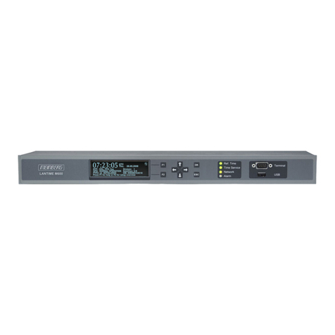
Meinberg LANTIME M300 User manual

Meinberg
Meinberg C600RS User manual

Meinberg
Meinberg LANTIME M300 User manual

Meinberg
Meinberg LANTIME M600 User manual

Meinberg
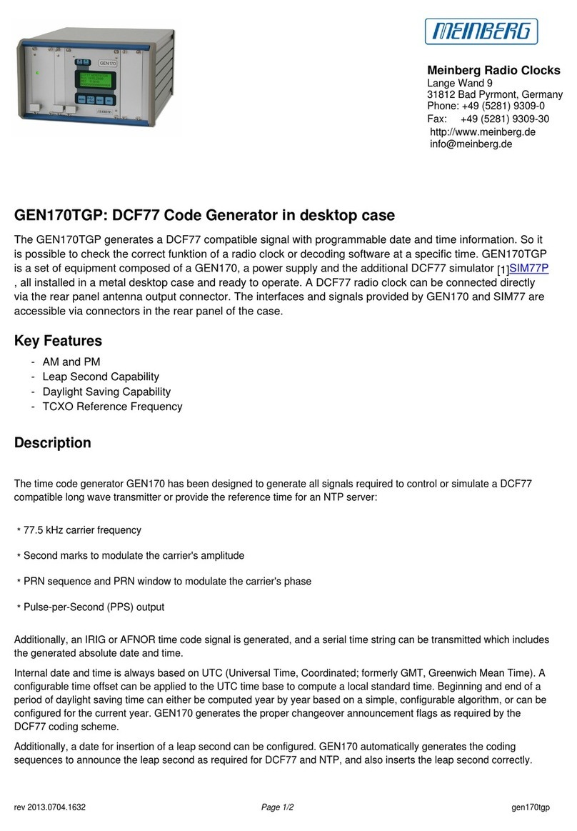
Meinberg GEN170TGP Manual