Meinberg GPS164-LQ/PPFO-3/REL-1/DAHS User manual

MANUAL
GPS164
PPFO-3/REL-1/DAHS
27th January 2016
Meinberg Radio Clocks GmbH & Co. KG


Table of Contents
1 General Details 1
2 Safety Hints 3
2.1 ContentoftheUSBstick....................................... 4
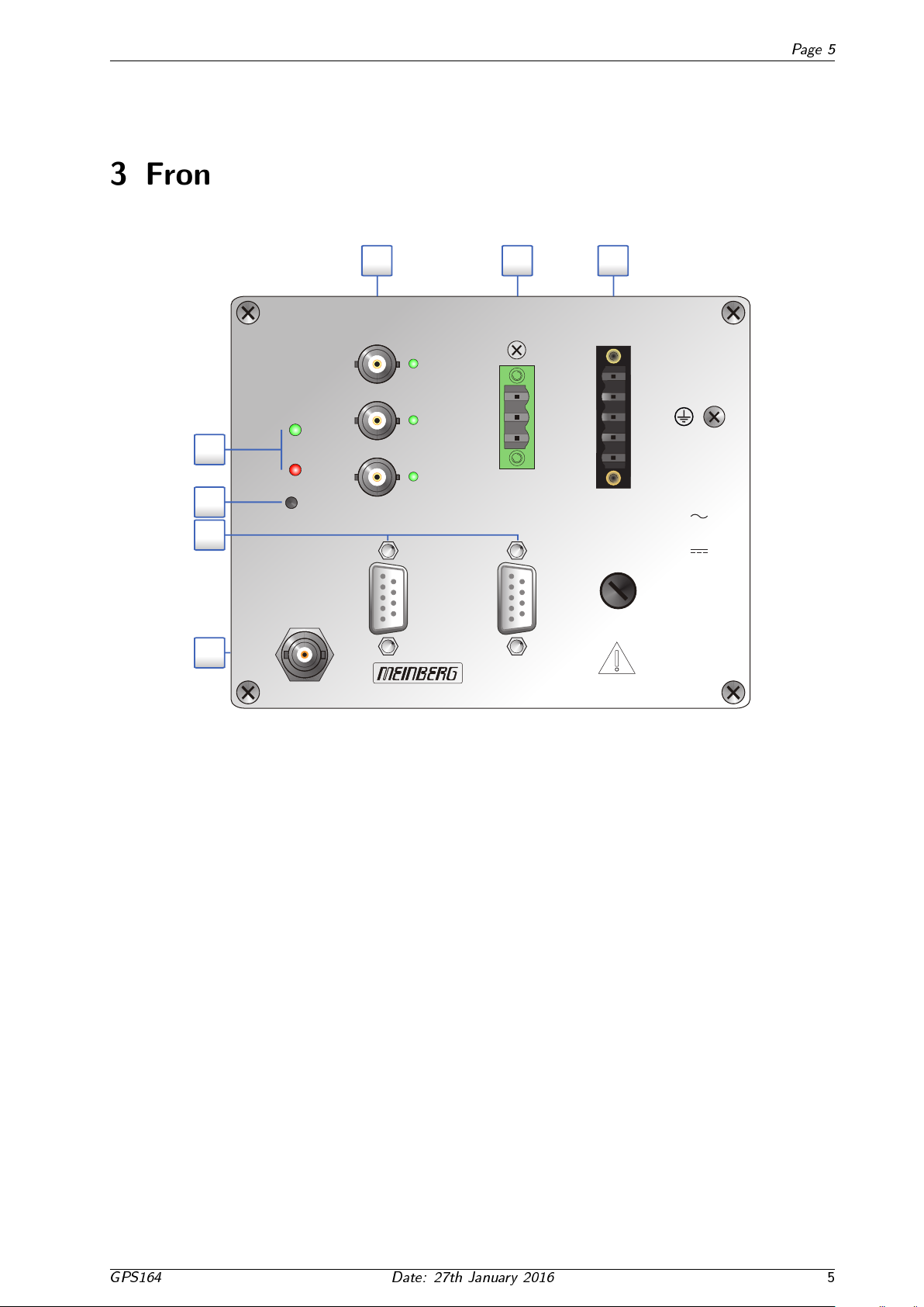
3 Frontpanel 5
4 General information about GPS164 6
5 Block diagram GPS164xhs 7
6 GPS164 Features 8
6.1 Time Zone and Daylight Saving . . . . . . . . . . . . . . . . . . . . . . . . . . . . . . . . . . . 8
6.2 Pulseoutputs ............................................. 9
6.3 AsynchronousSerialPorts....................................... 10
6.4 Timecodeoutputs .......................................... 10
6.4.1 Introduction.......................................... 10
6.4.2 GeneratedTimeCodes .................................... 11
6.4.3 Codegeneration........................................ 11
6.4.4 IRIGStandardFormat..................................... 12
6.4.5 AFNORStandardFormat................................... 13
6.4.6 Assignment of CF Segment in IEEE1344 Code . . . . . . . . . . . . . . . . . . . . . . . . 14
7 Installation 15
7.1 Powersupply.............................................. 16
7.2 Assignment of the DSUB connectors . . . . . . . . . . . . . . . . . . . . . . . . . . . . . . . . . 16
7.3 BNCconnectorGPSAnt ....................................... 17
7.4 ErrorRelay............................................... 17
7.5 MountingtheGPSAntenna...................................... 18
7.5.1 Assembly of the GPS antenna surge protector . . . . . . . . . . . . . . . . . . . . . . . . 18
7.6 PoweringUptheSystem ....................................... 20
7.7 ChangetheFuse............................................ 20
8 The Front Panel Layout 21
8.1 FAILLED ............................................... 21
8.2 LOCKLED .............................................. 21
8.3 OCxLEDs............................................... 21
8.4 BSLKey(hidden)........................................... 21
9 Technical Specifications GPS164DAHS 22
9.1 Technical Specications GPS Antenna . . . . . . . . . . . . . . . . . . . . . . . . . . . . . . . . 24
9.2 TimeStrings.............................................. 25
9.2.1 Format of the Meinberg Standard Time String . . . . . . . . . . . . . . . . . . . . . . . . 25
9.2.2 Format of the Meinberg GPS Time String . . . . . . . . . . . . . . . . . . . . . . . . . . 26
9.2.3 Format of the Meinberg Capture String . . . . . . . . . . . . . . . . . . . . . . . . . . . 27
9.2.4 Format of the SAT Time String . . . . . . . . . . . . . . . . . . . . . . . . . . . . . . . 28
9.2.5 Format of the Uni Erlangen String (NTP) . . . . . . . . . . . . . . . . . . . . . . . . . . 29
9.2.6 Format of the NMEA 0183 String (RMC) . . . . . . . . . . . . . . . . . . . . . . . . . . 31
9.2.7 Format of the NMEA 0183 String (GGA) . . . . . . . . . . . . . . . . . . . . . . . . . . 32
9.2.8 Format of the NMEA 0183 String (ZDA) . . . . . . . . . . . . . . . . . . . . . . . . . . 33
9.2.9 Format of the ABB SPA Time String . . . . . . . . . . . . . . . . . . . . . . . . . . . . 34
9.2.10 Format of the Computime Time String . . . . . . . . . . . . . . . . . . . . . . . . . . . . 35
9.2.11 Format of the RACAL standard Time String . . . . . . . . . . . . . . . . . . . . . . . . . 36
9.2.12 Format of the SYSPLEX-1 Time String . . . . . . . . . . . . . . . . . . . . . . . . . . . 37
0

Page 0
9.2.13 Format of the ION Time String . . . . . . . . . . . . . . . . . . . . . . . . . . . . . . . . 38
10 The program GPSMON32 39
10.1SerialConnection ........................................... 39
10.2NetworkConnection.......................................... 39
10.3OnlineHelp .............................................. 40
11 Imprint 41
0
Date: 27th January 2016 GPS164

Page 1
1 General Details
This manual contains important information for the installation and operation of
this device as well as for your safety. Make sure to read carefully before installing
andcommissioningthedevice.
Certain operating conditions may require the observance of additional safety
regulationsnotcoveredbythismanual.Nonobservanceofthismanualwillleadtoa
significantabatement ofthe securityprovidedby thisdevice. Securityofthe facility
where this product is integrated lies in the responsibility of the installer. The device
must be used only for purpose named in this manual, any other use especially
opteration above the limits specified in this document is considered as improper
use.
Keep all documents provided with the device for later reference.
This manual aims to qualied personnel only. Qualied personnel are those persons who are authorized to install,
commission and operated electrical systems and circuits in accordance with the respective national laws and safety
regulations.
Please note the following symbols:
Symbol
Beschreibung / Description
IEC 60417-5031
Gleichstrom /
Direct current
IEC 60417-5032
Wechselstrom /
Alternating current
IEC 60417-5017
Erdungsanschluss /
Earth (ground) Terminal
IEC 60417-5019
Schutzleiterklemme /
Protective Conductor Terminal
Vorsicht, Risiko eines elektrischen Schlages /
Caution, possibility of electric shock
ISO 7000-0434
Vorsicht, Risiko einer Gefahr /
Caution, Danger
2002/96/EC
Dieses Produkt fällt unter die B2B Kategorie. Zur Entsorgung
muss es an den Hersteller übergeben werden.
This product is handled as a B2B category product. In order to
secure a WEEE compliant waste disposal it has to be returned
to the manufacturer.
GPS164 Date: 27th January 2016
1

Page 2 1 General Details
2
Date: 27th January 2016 GPS164

Page 3
2 Safety Hints
WARNING!
This device is powered by a dangerous voltage. Nonobservance of the safety instructions of
this manual may lead to serious damage to persons and property and to danger to life!
Installtion, commissioning, maintenance and operation of this device are to be carried out by
qualified personnel only.
The general safety instructions and standards ( e.g. IEC, DIN, VDE, EN ) for installation and
work with high voltage equipment as well as the respective national standards and laws must
be observed.
NONOBSERVANCE MAY LEAD TO SERIOUS DAMAGE TO PERSONS AND PROPERTY AND TO
DANGER TO LIFE!
The device may not be opened. Repair services may only be carried out by the manufaturer.
Supply lines for this decice must be equipped via an appropriate switch that must be mounted
close to the device and must be marked as a mains switch for the device.
To ensure safe operation supply mains connected to this decice must be equipped with a fuse
and a fault-current circuit breaker according to the applicable national standards for safe
operation. The devide must be connected to a protective earth with low grounding resistance
according to the applicable national rules.
WARNING! DANGER TO LIFE BY ELECTRICAL SHOCK!
NO LIVE WORKING!
Wiring or any other work done the connectors particularly when connectors are opened may
never be carried out when the installation is energized.
All connectors must be covered to prevent from accidental contact to life parts.
ADVICE: ALWAYS ENSURE A PROPER INSTALLATION!
Additional safety information for installation devices
•
This device was developed and tested in accordance with the requirements dened in IEC61010-1 overvoltage
category II.
•
The device is intended for installation in an appropriate cubicle.
•
When the device is installed and operated in an end user device ( e.g a cubicle ), additional requirements
dened in IEC61010-1 must be fullled. Particularly the general standards for electrical safety (IEC, VDE,
DIN, ANSI e.g.) as well as the applicable national standards must be observed.
•
Protection against re must be ensured.
•
The device was developed and tested for industrial environments with a pollution grade 2 according to IEC
61010. Environments with a higher degree of pollution require additional measures such as installation in a
control box with air condition for example.
•
The device was designed and tested for a maximum ambient temperature of 50
◦
C.
•
Proper ventilation must be ensured, the device must not be covered.
GPS164 Date: 27th January 2016
3

Page 4 2 Safety Hints
Hints for Installation
•
The device may only be operated inside a building.
•
The device must be installed in an appropriate cubicle.
•
The device must be protected from moisture and heat.
•
The housing of the device must not be damaged for installation.
•
It is not allowed to drill holes in the housing.
•
The device must be protected from mechanical stress such as vibrations or shock.
•
The metal housing of the device is connected to the protective earth connector. Make sure not to underrup
crepage distances to energized parts close to the device. Make sure not to cause short circuits.
Safety Advice for the Lithium-Battery
This device is equipped with a Lithium-Battery Type VARTA CR 1/2 AA. The battery
may not be short-circuited, charged or exposed to heat. Battery exchange may only
be carried out by the manufacturer.
Hints for cleaning and maintenance
Attention!
Liquids can damage the electronics of the device! Liquid enters the housing of the
system and can cause a short circuit. Clean the device with a soft, dry or slightly
damp cloth. Do not use any solvents or detergents.
2.1 Content of the USB stick
Besides this manual, the provided USB stick includes a setup program for the monitor software GPSMON32. This
utility can be used to congure Meinberg GPS receivers via their serial ports and to display status information of
the module.
The software is executable under the
following operating systems:
- Windows 8
- Windows 7
- Windows VISTA
- Windows Server 2003
- Windows XP
- Windows 2000
- Windows NT
- Windows ME
- Windows 9x
http://www.meinberg.de/english/sw/#gpsmon
4
Date: 27th January 2016 GPS164

Page 5
3 Frontpanel
250 V/630 mA SB
GPS164-LQ/PPFO-3/REL-1/DAHS
GPS
Ant.
Lock
Fail
BSL
ENGLISH
1. Power supply connector / Fuse: 250 V / 630 mA (SlowBlow)
2. Error relay output, 3pin. DFK
3. Fiber-optic-outputs, ST-connector
4. Status-LEDs: Lock / Fail
5. BSL key (Boot Strap Loader)
6. Serial port COM 0 / COM 1, 9pin. D-SUB, female
7. GPS Antenna, BNC
DEUTSCH
1. Spannungsversorgung / Sicherung: 250 V / 630 mA (Träge)
2. Störmelderelaisausgang, 3pol. DFK
3. Fiber-Optik-Ausgänge, ST-Stecker
4. Status-LEDs: Lock / Fail
5. Taster BSL (Boot Strap Loader)
6. Serielle Schnittstelle COM 0 / COM 1, 9pol. D-SUB Buchse
7. GPS Antenne, BNC
COM 0
16
59
NO
NC
CO
COM 1
16
59
100 V - 240 V
50 Hz - 60 Hz
100 V - 240 V
21
6
N/-
L/+
7
4
FO
FO
FO
Out 1
Out 2
Out 3
3
Error
5
GPS164 Date: 27th January 2016
5

Page 6 4 General information about GPS164
4 General information about GPS164
The satellite receiver clock GPS164xHS has been designed to provide an extremly precise time reference for
the generation of programmable pulses. High precision available 24 hours a day around the whole world is the
main feature of the new system which receives it's information from the satellites of the Global Positioning System.
The Global Positioning System (GPS) is a satellite-based radio-positioning, navigation, and time-transfer sys-
tem. It was installed by the United States Departement of Defense and provides two levels of accuracy: The
Standard Positioning Service (SPS) and the Precise Positioning Service (PPS). While PPS is encrypted and only
available for authorized (military) users, SPS has been made available to the general public.
GPS is based on accurately measuring the propagation time of signals transmitted from satellites to the users
receiver. A nominal constellation of 24 satellites together with 3 active spares in six orbital planes 20000 km
over ground provides a minimum of four satellites to be in view 24 hours a day at every point of the globe.
Four satellites need to be received simultaneously if both receiver position (x, y, z) and receiver clock oset from
GPS system time must be computed. All the satellites are monitored by control stations which determine the
exact orbit parameters as well as the clock oset of the satellites on-board atomic clocks. These parameters
are uploaded to the satellites and become part of a navigation message which is retransmitted by the satellites in
order to pass that information to the users receiver.
The high precision orbit parameters of a satellite are called ephemeris parameters whereas a reduced precision
subset of the ephemeris parameters is called a satellites almanac. While ephemeris parameters must be evaluated
to compute the receivers position and clock oset, almanac parameters are used to check which satellites are in
view from a given receiver position at a given time. Each satellite transmits its own set of ephemeris parameters
and almanac parameters of all existing satellites.
6
Date: 27th January 2016 GPS164

Page 7
5 Block diagram GPS164xhs
optional
lightning
protector
antenna/
converter
unit
RS232
driver
RS485
driver
timecode
modulator,
pulse sync.
and
output MUX
optical isolation
RS232 COM0
RS232 (RS485) COM1
IRIG RS485
programmable pulses
IRIG modulated
IRIG unmodulated
power supply
GPS-signal (IF)
LO-frequency
RG58-cable up to 250 meters
without additional amplifier
IF-circuit microcontroller
with
Flash Memory
correlator
DCF77
simulation
master
oscillator D/A-converter
GPS164xHS
SRAM
EEPROM
data memories
real time clock
power
19-72VDC (DHS)
85-264VAC (AHS)
100-240VDC (DAHS)
simulated
DCF77-output
antenna power
internal power
sample
clock
data
addr/data
clock
clock
DCF-pulses
clock
clock
control
voltage
Tx/Rx
COM0
COM1
data
3
2
addr/data
prog. pulses 3
refclk.
timecode
GPS164 Date: 27th January 2016
7

Page 8 6 GPS164 Features
6 GPS164 Features
The GPS164 is designed for mounting on a DIN rail. The front panel integrates ve LED indicators, a hidden
push button, an eight-pole terminal block, three DSUB and three BNC-connectors. The receiver is connected to
the antenna/converter unit by a 50 Ohm coaxial cable with a length up to 300 m (when using an RG58 cable).
It is possible to connect up to four receivers to one antenna by using an optional antenna diplexer.
The navigation message coming from the satellites is decoded by the GPS164xHS's microprocessor in order
to track the GPS system time with an accuracy of better than +/-250 ns. Compensation of the RF signal's
propagation delay is done by automatical determination of the receiver's position on the globe. A correction value
computed from the satellites' navigation messages increases the accuracy of the board's TCXO to +/-5x10-9 and
automatically compensates the oscillators aging. The last recent value is restored from the battery memory at
power-up.
6.1 Time Zone and Daylight Saving
GPS system time diers from the universal time scale UTC (Universal Time Coordinated) by the number of leap
seconds which have been inserted into the UTC time scale after GPS has been initiated in 1980. The current
number of leap seconds is part of the navigation message supplied by the satellites, so GPS170SVs internal real
time is based on UTC.
Conversion to local time including handling of daylight saving year by year can be done by the receivers micro-
processor. As standard the switchover times are set to the values of the European Union (Central Europe). The
Manual GPSMON32 describes how parameter setting for other locations is done. It is possible to deactivate
the automatic switching to/from daylight saving.
8
Date: 27th January 2016 GPS164

6.2 Pulse outputs Page 9
6.2 Pulse outputs
The satellite controlled clock GPS164 is equipped with a pulse generator providing three output channels inde-
pendently congurable using the software GPSMON32. The active state of each output is settable to either high
or low, pulse duration may be congured between 10ms an 10s in steps of 10ms. By default, pulse outputs are
disabled until rst synchronization of the receiver, however outputs can be congured to be enabled immediately
after power up. Pulses are output via three bre optic transmitters (850 nm, ST-Connector).
The following modes can be congured for each channel independently:
Timer mode:
Three on- and o-times per day per channel programmable
Cyclic mode:
Generation of peropdically repeated pulses.
A cycle time of two seconds would generate a pulse at
0:00:00, 0:00:02, 0:00:04 etc.
DCF77-Simulation
mode:
The corresponding output simulates the DCF77 time telegram.
The time marks are representing the local time as congured by the user.
Time zone of the signal is congurable to either local time or UTC.
DCF77-M59
Generates a modied DCF77 telegram with a 500 ms pulse inserted in
the 59th second gap. Time zone of the signal is congurable to either local time or UTC.
Single Shot Mode:
A single pulse of programmable length is generated once a day at a
programmable point of time
Per Sec.
Per Min.
Per Hr. modes:
Pulses each second, minute or hour
Status:
One of three status messages can be emitted:
'position OK': The output is switched on if the receiver was able to
compute its position
'time sync': The output is switched on if the internal timing is
synchronous to the GPS-system
'all sync': Logical AND of the above status messages.
The output is active if position is calculated AND the
timing is synchronized
Time code
The un-modulated IRIG or AFNOR signal of the built in time code generator
is made available at the respective output.
COM Time String
The time string of the serial port COM1 is made available at the respective
output.
Idle-mode:
The output is inactive.
GPS164 Date: 27th January 2016
9

Page 10 6 GPS164 Features
6.3 Asynchronous Serial Ports
Two asynchronous serial interfaces (RS-232) called COM0 and COM1 are available to the user. In the default
mode of operation, the serial outputs are disabeled until the receiver has synchonized after power up. However,
the system can be congured to enable those outputs immediately after power-up. Transmission speeds, framings
and the kind of the time string can be congured separately. The serial ports are sending a time string either
once per second, once per minute or on request with ASCII "?" only. The format of the output strings is ASCII,
see the technical specications for details. The corresponding parameters can be set up by GPSMON32 (included
Windows software) using serial port COM0.
6.4 Time code outputs
6.4.1 Introduction
The transmission of coded timing signals began to take on widespread importance in the early 1950s. Especially
the US missile and space programs were the forces behind the development of these time codes, which were used
for the correlation of data. The denition of time code formats was completely arbitrary and left to the individual
ideas of each design engineer. Hundreds of dierent time codes were formed, some of which were standardized
by the "Inter Range Instrumentation Group" (IRIG) in the early 60s. Detailed information about IRIG and other
time codes can be found on
http://www.meinberg.de/english/info/irig.htm
Except these time codes other formats, like NASA36, XR3 or 2137, are still in use. The module GPS164TDHS
however generates IRIG-B or AFNOR NFS500 only.
Selection of the generated time code is done by using the monitor program GPSMON32.
10
Date: 27th January 2016 GPS164

6.4 Time code outputs Page 11
6.4.2 Generated Time Codes
The internal time code generator may be congured to produce various pulse width modulated IRIG-B or AFNOR
signals. Codes can be output via the front panel bre optic ports FO1. . . FO3.
a) B002: 100 pps, DCLS signal, no carrier
BCD time-of-year
b) B003: 100 pps, DCLS signal, no carrier
BCD time-of-year, SBS time-of-day
c) B006: 100 pps, DCLS Signal, no carrier
BCD time-of-year, Year
d) B007: 100 pps, DCLS Signal, no carrier
BCD time-of-year, Year, SBS time-of-day
e) AFNOR : Code according to NFS-87500, 100 pps, wave signal,
1kHz carrier frequency, BCD time-of-year, complete date,
SBS time-of-day, Signal level according to NFS-87500
f) IEEE1344: Code according to IEEE1344-1995, 100 pps, AM sine wave signal,
1kHz carrier frequency, BCD time-of-year, SBS time-of-day,
IEEE1344 extensions for date, timezone, daylight saving and
leap second in control functions (CF) segment.
(also see table 'Assignment of CF segment in IEEE1344 mode')
g) C37.118: C37.118(DC) Code acc. C37.118, 100 pps, no carrier, BCD time-of-year,
SBS time-of-day,C37.118 extensions for date, timezone, daylight
saving and leap second in control functions (CF) segment
( also see table `Assignment of CF segment in IEEE1344 mode' but
sign bit of local oset is inverted )
6.4.3 Code generation
In the default mode of operation the IRIG/AFNOR timecode outputs are disabled until the GPS-receiver has been
synchronized after power-up. Due to that the generation of the IRIG-code only starts after synchronization.
If the code must be available immediately after power-up, the software GPSMON32 can be used to enable
the time code output without synchronization of the GPS-receiver by setting the enable ag 'pulses' to 'always'.
In this mode of operation the IRIG-code is not locked to UTC-second until synchronization.
GPS164 Date: 27th January 2016
11

Page 12 6 GPS164 Features
6.4.4 IRIG Standard Format
12
Date: 27th January 2016 GPS164

6.4 Time code outputs Page 13
6.4.5 AFNOR Standard Format
GPS164 Date: 27th January 2016
13

Page 14 6 GPS164 Features
6.4.6 Assignment of CF Segment in IEEE1344 Code
Bit No. Designation Description
49 Position Identier P5
50 Year BCD encoded 1
51 Year BCD encoded 2 low nibble of BCD encoded year
52 Year BCD encoded 4
53 Year BCD encoded 8
54 empty, always zero
55 Year BCD encoded 10
56 Year BCD encoded 20 high nibble of BCD encoded year
57 Year BCD encoded 40
58 Year BCD encoded 80
59 Position Identier P6
60 LSP - Leap Second Pending set up to 59s before LS insertion
61 LS - Leap Second 0 = add leap second, 1 = delete leap second
1.)
62 DSP - Daylight Saving Pending set up to 59s before daylight saving changeover
63 DST - Daylight Saving Time set during daylight saving time
64 Timezone Oset Sign sign of TZ oset 0 = '+', 1 = '-'
65 TZ Oset binary encoded 1
66 TZ Oset binary encoded 2 Oset from IRIG time to UTC time.
67 TZ Oset binary encoded 4 Encoded IRIG time plus TZ Oset equals UTC at all times!
68 TZ Oset binary encoded 8
69 Position Identier P7
70 TZ Oset 0.5 hour set if additional half hour oset
71 TFOM Time gure of merit
72 TFOM Time gure of merit time gure of merit represents approximated clock error.
2.)
73 TFOM Time gure of merit 0x00 = clock locked, 0x0F = clock failed
74 TFOM Time gure of merit
75 PARITY parity on all preceding bits incl. IRIG-B time
1.) current rmware does not support leap deletion of leap seconds
2.) TFOM is cleared, when clock is synchronized rst after power up. see chapter Selection of generated timecode
14
Date: 27th January 2016 GPS164

Page 15
7 Installation
Description Connector Type Cable
-
COM 0 / COM 1
9pin. Sub-D female RS232, galvanically shielded data line
isolated, oating Uiso > 300 VDC
FO Out 1-3
ST-connector 850 nm, Fiber optic GI 50/125
µ
m or
GI62.5/125
µ
m gradientbre
GPS-Antenna
BNC GPS-IF Signal RG58U, RG213
Error relay
MSTB 2,5/ 3-ST-5,08 oating relay H05V-K, min. 0.75 mm
2
*
with connector housing max. 2.5 mm
2
, with ferrules
change-over contact line colors by DIN VDE 0293-308
torque min 0,5 Nm
torque max 0,6 Nm
Power
MSTB 2,5/ 5-STF-5,08 powerline H05VV-F 3G, min. 0.75 mm
2
**
with connector housing also see 7.1 max. 2.5 mm
2
, with ferrules
line colors by DIN VDE 0293-308
torque min 0,5 Nm
torque max 0,6 Nm
Type of cable
* **
WARNING: DANGER TO LIFE BY ELECTRICAL SHOCK!
NOLIVEWORKING!
Donotcarryoutelectricalinstallationonopenconnectors,terminals
orcableswhentheyareenergized!Allconnectorsmustbeequippedwith
suitablecoverstopreventfromelectricalshockorhazard!
Alwaysensureaproperinstallation!
GPS164 Date: 27th January 2016
15

Page 16 7 Installation
7.1 Power supply
Supply voltage and protective earth must be applied to the device via the 5-pole connector `Power'. The supply
line used for this device must be equipped with an appropriate switch that must be mounted close to the device
and must be marked as a mains switch for the device. Furthermore, to ensure safe operation supply mains con-
nected to this device must be equipped with a fuse and a fault-current circuit breaker according to the applicable
national standards. The device must be connected to a protective earth with low grounding resistance according
to the applicable national rules.
max. 25 VA
100 V to 240 V
100 V to 240 V
max. 8 W
47 Hz to 63 Hz
Supply Input voltage Power consumption Frequency
WARNING: DANGERTOLIFEBYELECTRICALSHOCK!
NOLIVEWORKING!
Terminalsofthepowerconnectorareenergizedatdangerousvoltagelevels!
Donotcarryoutelectricalworkswhenterminalsorcablesareenergized!
Allconnectorsmustbeequippedwithsuitablecoverstopreventfromelectrical
shockorhazard!
7.2 Assignment of the DSUB connectors
The serial ports COM0 and COM1 are accessible via nine-pole DSUB connectors in the frontpanel. These RS-232
interfaces can be connected to a computer by using a standard modem cable. TxD describes the sending, RxD
the receiving line of the GPS164xHS.
16
59
RS-232
COM 0 / COM 1
TxD
RxD
GND
WARNING: DANGERTOLIFEBYELECTRICALSHOCK!
NOLIVEWORKING!
Disconnectbothsidesoftheserialportcablebeforeworkingonitsconnectors.
Thisdeviceisequippedwithtwogalvanicallyisolatedserialports.Hazardous
voltagesmaybeappliedtotheserialcableifaconnecteddeviceisfaulty.
Allconnectorsmustbeequippedwithsuitablecoverstopreventfromelectrical
shockorhazard!
16
Date: 27th January 2016 GPS164
Table of contents
Other Meinberg Receiver manuals

Meinberg
Meinberg GPS170 BGT User manual

Meinberg
Meinberg RU226 Manual

Meinberg
Meinberg PZF511 Manual

Meinberg
Meinberg TCR180USB-EL User manual

Meinberg
Meinberg PZF180 User manual

Meinberg
Meinberg DCF77 User manual

Meinberg
Meinberg DCF600USB User manual

Meinberg
Meinberg GNS165DHS User manual

Meinberg
Meinberg GPS180 User manual

Meinberg
Meinberg TCR509 User manual
Popular Receiver manuals by other brands

Pioneer
Pioneer SC-09TX - Elite AV Network Receiver Service manual

Kathrein
Kathrein UFS 641si operating manual

Bazooka
Bazooka RB33W Product information

Semtech
Semtech TSWIRX-LI-EVM user guide

Digitus
Digitus DA-10190 manual

Silent Call Communications
Silent Call Communications Sidekick II SK09214-2 user guide