Meinberg TCR180USB-EL User manual

MANUAL
TCR180USB-EL Setup Guide
Time Code Receiver
15th October 2020
Meinberg Funkuhren GmbH & Co. KG


Table of Contents
1 Imprint 1
2 Important Safety Information 2
2.1 Important Safety Instructions and Protective Measures ......................... 2
2.2 Used Symbols ................................................. 3
2.3 Cleaning and Care .............................................. 5
2.4 Return of Electrical and Electronic Equipment .............................. 6
3 Introduction 7
4 General information about time code 8
4.1 Description of IRIG-Codes ......................................... 8
4.2 IRIG Standard Format ............................................ 9
4.3 AFNOR Standard Format .......................................... 10
5 Technical Function TCR180USB-EL 11
5.1 Functional Description ............................................ 12
5.2 Internal RTC .................................................. 14
5.3 Input signals .................................................. 14
5.4 Input Impedance ............................................... 14
5.5 Optocoupler Input .............................................. 14
6 TCR180 USB Connectors 15
6.1 USB 2.0 high speed Interface ........................................ 15
6.2 TCR180USB-EL Status LEDs ....................................... 15
6.3 Time Code DCLS (unmodulated) Input .................................. 16
6.4 Time Code AM (modulated) Input ..................................... 16
7 Before you start 17
7.1 Scope of delivery ............................................... 17
7.2 Disposal of Packaging Materials ...................................... 18
7.3 Download MBGMON ............................................ 18
8 System Installation 19
8.1 Connecting the System ........................................... 19
9 Put the TCR180USB-EL into operation 20
9.1 Configuration of TCR180USB-EL ..................................... 21
9.2 Set TCR180USB-EL as reference ..................................... 23
10 Technical Specifications TCR180USB-EL 25
11 RoHS and WEEE 26
12 Declaration of Conformity 27
Date: 15th October 2020 TCR180USB-EL Setup Guide

1 Imprint
1 Imprint
Meinberg Funkuhren GmbH & Co. KG
Lange Wand 9, 31812 Bad Pyrmont / Germany
Phone: + 49 (0) 52 81 / 93 09 - 0
Fax: + 49 (0) 52 81 / 93 09 - 230
Internet: https://www.meinbergglobal.com
Mail: [email protected]
Date: 15.10.2020
TCR180USB-EL Setup Guide Date: 15th October 2020 1

2 Important Safety Information
2.1 Important Safety Instructions and Protective Measures
The following safety instructions must be respected in all operating and installation phases of the device. Non-
observance of safety instructions, or rather special warnings and operating instructions in product manuals,
violates safety standards, manufacturer instructions and proper usage of the device. Meinberg Funkuhren shall
not be responsible for any damage arising due to non-observance of these regulations.
Depending on your device or the installed options
some information is not valid for your device.
The device satisfies the requirements of the following EU regulations: EMC-Directive,
RoHS Directive.
If a procedure is marked with the following signal words, you may only continue, if you have understood and
fulfilled all requirements. In this documentation dangers and indications are classified and illustrated as follows:
DANGER!
The signal word indicates an imminently hazardous situation with a high risk level . This notice
draws attention to an operating procedure or similar proceedings, of which a non-observance may
result in serious personal injury or death .
WARNING!
The signal word indicates a hazard with a medium risk gradient . This notice draws attention to an
operating procedure, a procedure or the like which, if not followed, can lead to serious injuries ,
possibly resulting in death .
CAUTION!
The signal word indicates a hazard with a low risk gradient . This notice draws attention to an
operating procedure, a procedure or the like which, if not followed, can lead to minor injuries .
ATTENTION!
This notice draws attention to an operating procedure, a procedure or the like which, if not followed,
can cause damage to the product or loss of important data .
2 Date: 15th October 2020 TCR180USB-EL Setup Guide

2 Important Safety Information
2.2 Used Symbols
The following symbols and pictograms are used in this manual. To illustrate the source of danger, pictograms
are used, which can occur in all hazard classes.
Symbol
Beschreibung / Description
IEC 60417-5031
Gleichstrom / Direct current
IEC 60417-5032
Wechselstrom / Alternating current
IEC 60417-5017
Erdungsanschluss / Earth (ground) terminal
IEC 60417-5019
Schutzleiteranschluss / Protective earth (ground) terminal
ISO 7000-0434A
Vorsicht / Caution
IEC 60417-6042
Vorsicht, Risiko eines elektrischen Schlages / Caution, risk of electric shock
IEC 60417-5041
Vorsicht, heiße Oberfläche / Caution, hot surface
IEC 60417-6056
Vorsicht, Gefährlich sich bewegende Teile / Caution, moving fan blades
IEC 60417-6172
Trennen Sie alle Netzstecker / Disconnection, all power plugs
IEC 60417-5134
Elektrostatisch gefährdete Bauteile / Electrostatic Sensitive Devices
IEC 60417-6222
Information generell / Information general
2012/19/EU
Dieses Produkt fällt unter die B2B Kategorie. Zur Entsorgung muss es an den
Hersteller übergeben werden.
This product is handled as a B2B category product. In order to secure a WEEE
compliant waste disposal it has to be returned to the manufacturer.
TCR180USB-EL Setup Guide Date: 15th October 2020 3

The manuals for a product are included in the scope of delivery of the device on a USB stick. The manuals can
also be obtained via the Internet. Enter www.meinbergglobal.com into your browser, then enter the correspond-
ing device name in the search field at the top.
This manual contains important safety instructions for the installation and operation of the
device. Please read this manual completely before using the unit.
This device may only be used for the purpose described in this manual. In particular, the given
limits of the device must be observed. The safety of the installation in which the unit is
integrated is the responsibility of the installer!
Non-observance of these instructions can lead to a reduction in the safety of this device!
Please keep this manual in a safe place.
This manual is intended exclusively for electricians or persons trained by an electrician who are familiar with
the applicable national standards and safety rules. Installation, commissioning and operation of this device may
only be carried out by qualified personnel.
4 Date: 15th October 2020 TCR180USB-EL Setup Guide

2 Important Safety Information
2.3 Cleaning and Care
ATTENTION!
Do not wet clean the appliance! Penetrating water can cause considerable dangers to
the user (e.g., electric shock).
Liquid can destroy the electronics of the device! Liquid penetrates into the housing
of the device and can cause a short circuit of the electronics.
Only clean with a soft, dry cloth. Never use solvents or cleaners.
TCR180USB-EL Setup Guide Date: 15th October 2020 5

2.4 Return of Electrical and Electronic Equipment
ATTENTION!
WEEE Directive on Waste Electrical and Electronic Equipment 2012/19 / EU
(WEEE Waste Electrical and Electronic Equipment)
Separate Collection
Product Category: According to the device types listed in the WEEE Directive, Appendix 1,
this product is classified as an IT and communication device.
This product meets the labeling requirements of the WEEE Directive. The product symbol on
the left indicates that this electronic product must not be disposed of in domestic waste.
Return and Collection Systems
For returning your old equipment, please use the country-specific return and collection systems
available to you or contact Meinberg.
The withdrawal may be refused in the case of waste equipment which presents a risk to
human health or safety due to contamination during use.
Return of used Batteries
Batteries marked with one of the following symbols may not be disposed of together with the
household waste according to the EU Directive.
6 Date: 15th October 2020 TCR180USB-EL Setup Guide

3 Introduction
3 Introduction
This Setup Guide is a systematically structured guide to support you during the initial setup of your Meinberg
product. The individual chapters describe general functions, installation and essential technical data. The Setup
Guide also describes the most important parameters which have to be configured in the respective management
program for a quick startup of your product.
The TCR180USB-EL is a time code receiver for decoding modulated and unmodulated IRIG, AFNOR and
IEEE time codes and is used for time synchronization of computers with no serial interface or no available PCI
slot. It is also suitable for the verification of time code outputs. The board will be configured by the program
MBGMON.
TCR180USB-EL Setup Guide Date: 15th October 2020 7

4 General information about time code
The transmission of coded timing signals began to take on widespread importance in the early 1950´s. Espe-
cially the US missile and space programs were the forces behind the development of these time codes, which
were used for the correlation of data. The definition of time code formats was completely arbitrary and left to
the individual ideas of each design engineer. Hundreds of different time codes were formed, some of which were
standardized by the "Inter Range Instrumentation Group" (IRIG) in the early 60´s.
Except these "IRIG Time Codes" other formats, like NASA36, XR3 or 2137, are still in use. The board
TCR180USB-EL however only decodes IRIG-A, IRIG-B, AFNOR NFS 87-500 or IEEE1344 formats.
The AFNOR code is a variant of the IRIG-B format. Within this code the complete date is transmitted in-
stead of the "Control Functions" of the IRIG telegram.
4.1 Description of IRIG-Codes
The specification of individual IRIG time code formats is defined in IRIG Standard 200-04. They are described
by an alphabetical character followed by a three-digit number sequence. The following identification is taken
from the IRIG Standard 200-98):
character bit rate designation A 1000 pps
B 100 pps
1st digit form designation 0 DC Level Shift pulse width modulated
1 sine wave carrier amplitude modulated
2nd digit carrier resolution 0 no carrier (DC Level Shift)
1 100 Hz, 10 msec resolution
2 1 kHz, 1 msec resolution
3 10 kHz, 100 µsec resolution
3rd digit coded expressions 0 BCD(TOY) , CF, SBS
1 BCD(TOY) , CF
2 BCD(TOY)
3 BCD(TOY) , SBS
4 BCD(TOY) , BCD(YEAR) , CF, SBS
5 BCD(TOY) , BCD(YEAR) , SBS
6 BCD(TOY) , BCD(YEAR)
7 BCD(TOY) , BCD(YEAR) , SBS
———————————————————————————————————————–
BCD: time of year, BCD-coded
CF: Control-Functions (user defined)
SBS: seconds of day since midnight (binary)
8 Date: 15th October 2020 TCR180USB-EL Setup Guide

4 General information about time code
4.2 IRIG Standard Format
TCR180USB-EL Setup Guide Date: 15th October 2020 9

4.3 AFNOR Standard Format
10 Date: 15th October 2020 TCR180USB-EL Setup Guide
5 Technical Function TCR180USB-EL
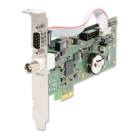
The TCR180USB-EL is an IRIG receiver to be connected to the USB interface of a computer and is used to
receive and decode modulated and unmodulated IRIG, AFNOR and IEEE time codes.
With modulated codes, the time information is transmitted by modulating the amplitude of a sine wave carrier.
Unmodulated IRIG codes transmit the time information by variation of the width of pulses.
The automatic gain control of the receiver for modulated codes allows the decoding of IRIG signals with an
amplitude of the sine carrier of 800 mVss to 8 Vss . The potential-free signal input via SMB connectors has an
impedance of 600 Ω.
The input for unmodulated or ’DC Level Shift’ time codes also has an SMB connector. The receiver circuit
of the TCR180USB-EL is insulated from the signal input via an integrated optocoupler.
TCR180USB-EL Setup Guide Date: 15th October 2020 11

5.1 Functional Description
The received IRIG codes are used to synchronize the internal clock as well as the capacitor-buffered real time
clock (RTC) of the TCR180USB-EL, where each received telegram is subjected to a consistency check. If a
telegram error is detected, the internal clock switches to free-running mode. In this case the drift of the time
base is limited by an oscillator control to about 1 µs/sec.
The IRIG codes do not contain a complete date but only an day of year information, the complete date in-
formation is kept in the RTC and in the internal clock of the TCR180USB-EL.
The internal system clock is always set to the received IRIG time, which might have a local
offset to UTC. Only if TCR180USB-EL is configured with this offset, Meinberg driver software is able to set the
system time of the computer correctly.
IRIG telegrams don’t include announcers for the change of time zone (daylight saving on/off) or for the in-
sertion of a leap second. Hence the clock will switch into free running mode in case of such event, and
resynchronize afterwards.
The board TCR180USB-EL decodes the following formats:
A133: 1000pps, amplitude modulated sine wave signal, 10 kHz carrier frequency
BCD time of year, SBS time of day
A132: 1000pps, amplitude modulated sine wave signal, 10 kHz carrier frequency
BCD time of year
A003: 1000pps, DC Level Shift pulse width coded, no carrier
BCD time of year, SBS time of day
A002: 1000pps, DC Level Shift pulse width coded, no carrier
BCD time of year
B123: 100pps, amplitude modulated sine wave signal, 1 kHz carrier frequency
BCD time of year, SBS time of day
B122: 100pps, amplitude modulated sine wave signal, 1 kHz carrier frequency
BCD time of year
B003: 100pps,DC Level Shift pulse width coded, no carrier
BCD time of year, SBS time of day
B002: 100pps, DC Level Shift pulse width coded, no carrier
BCD time of year
12 Date: 15th October 2020 TCR180USB-EL Setup Guide
5 Technical Function TCR180USB-EL
B126: 100 pps, AM sine wave signal, 1 kHz carrier frequency
BCD time-of-year, Year
B127: 100 pps, AM sine wave signal, 1 kHz carrier frequency
BCD time-of-year, Year, SBS time-of-day
B006: 100 pps, DC Level Shift, no carrier
BCD time-of-year, Year
B007: 100 pps, DC Level Shift, no carrier
BCD time-of-year, Year, SBS time-of-day
AFNOR NFS 87-500: 100pps, amplitude modulated sine wave signal, 1 kHz carrier frequency
BCD time of year, complete date, SBS time of day
IEEE 1344: Code according to IEEE 1344-1995, 100 pps, AM sine wave signal,
1kHz carrier frequency, BCD time-of-year, SBS time-of-day,
IEEE 1344 extensions for date, timezone, daylight saving and
leap second in control functions (CF) segment.
(also see table ’Assignment of CF segment in IEEE 1344 mode’)
IEEE C37.118: Like IEEE 1344 - with UTC offset to be applied reversely
Additional codes are available on request
TCR180USB-EL Setup Guide Date: 15th October 2020 13

5.2 Internal RTC
If the power supply of the TCR180USB-EL is interrupted the internal RTC continues to run on quartz basis. In
this case the power supply of the clock will be provided by a built-in capacitor which has been charged via the
USB power supply. This allows an independent power supply of the internal clock for about five days.
At restarting the TCR180USB-EL the time/date will be read once from the internal RTC and set as sys-
tem time of the TCR180USB-EL. After five days the TCR180USB-EL cannot read out the correct time and date
from the internal clock during the start procedure and consequently is not able to synchronize correctly to the
received IRIG telegram. In this case it is necessary to set the date and time of the internal clock manually with
the monitor program (see Configuration of the TCR180USB-EL).
5.3 Input signals
Amplitude modulated and Pulse width modulated signals IRIG-A/B (or AFNOR) codes must be connected to
the SMB-jack connector in the housing of TCR180USB-EL. A shielded or a twisted pair cable should be used.
The IRIG code used must be configured with the monitor software.
i
The board TCR180USB-EL can’t be used to decode amplitude modulated and DC Level Shift
signals simultaneously. Depending on the selected code, only the signal at the SMB-connector
is decoded.
5.4 Input Impedance
The IRIG specification does not define values for the output impedance of the transmitter or the input impedance
of the receiver for modulated codes. As a result, the manufacturers of IRIG components have been free to choose
these values, which means that not all devices are compatible with each other. For example, if the generator has
a high output impedance and the IRIG reader has a low input impedance, the signal level at the receiver input
may be too low for the evaluation. Please refer to chapter 6.3 or 6.4 for the input impedances of the respective
signal input.
5.5 Optocoupler Input
Pulse width modulated (DC Level Shift) codes are insulated by an onboard photocoupler.
The internal series impedance allows direct operation with input signals that have a maximum high level
of +12 V (e.g. TTL or RS-422). For higher signal voltages, an additional series resistor must be provided
externally so that the maximum diode current of 50 mA is not exceeded. At the same time, the series resistor
should be dimensioned in such a way that at least a current of 10 mA flows, so that a safe through-connection
of the optocoupler is guaranteed.
14 Date: 15th October 2020 TCR180USB-EL Setup Guide

6 TCR180 USB Connectors
1
2
3
4
6.1 USB 2.0 high speed Interface
Power supply: 5 V DC via USB
Connection type: micro-USB type B
6.2 TCR180USB-EL Status LEDs
LED Indicators
Fail: red: Time Sync Error
Tele.: green: Time Code data consistent
red: Time Code data inconsistent
Data: green: IRIG data available
rot: IRIG data not available
yellow: Jitter to large
Init: blue: while the receiver passes through
the initialization phase
green: the oscillator has warmed up
TCR180USB-EL Setup Guide Date: 15th October 2020 15

6.3 Time Code DCLS (unmodulated) Input
Input signal: Time Code DCLS, pulse-width
modulated (e.g. IRIG-B00x)
Isolation voltage: 3750 Vrms
internal resistance: 330 Ohm
max. input current: 25 mA
Connection type: SMB male
Cable: shielded coax line
TC DCLS In
6.4 Time Code AM (modulated) Input
Signal output: Time Code AM (amplitude modulated sine wave signal)
Signal level: 800 mVss /8Vss (MARK/SPACE)
impedance: std. 600 Ohm
(optional 50 Ohm / 5 kOhm)
Isolation Voltage: 3000 V DC
Connection type: SMB male
Cable: shielded coax line
TC AM In
16 Date: 15th October 2020 TCR180USB-EL Setup Guide
7 Before you start
7 Before you start
7.1 Scope of delivery
Included in delivery of a TCR180USB-EL:
1. TCR180USB-EL
2. 1 x 1 m cable RG174 (SMB-female - BNC female)
3. 1 x 1.8 m USB interface cable (USB-A - micro USB-B)
4. 1 x USB stick (driver software)
Carefully unpack the product and all accessories and put them aside. Check the scope of delivery with the
packing list to ensure that no parts are missing. If any of the listed contents are missing, please contact Mein-
berg Funkuhren.
Check the system for shipping damage. If the system is damaged or cannot be put into operation, contact
Meinberg Funkuhren immediately. Only the recipient (the person or company receiving the system) can assert
a claim against freight forwarder for shipping damage.
Meinberg recommends that you keep the original packaging materials for possible future transport.
TCR180USB-EL Setup Guide Date: 15th October 2020 17
Table of contents
Other Meinberg Receiver manuals

Meinberg
Meinberg PZF510 User manual

Meinberg
Meinberg PZF180 User manual

Meinberg
Meinberg GNS165XHS User manual

Meinberg
Meinberg GPS180SV User manual

Meinberg
Meinberg TCR509 User manual

Meinberg
Meinberg GPS170 BGT User manual

Meinberg
Meinberg FM614 Manual

Meinberg
Meinberg TCR180PEX-EL User manual

Meinberg
Meinberg GPS180 User manual

Meinberg
Meinberg RU226 Manual