MEIRUIKE RK267M Series User manual

RK267 M

、…………………………………
、………………………
、……………………
、……………………………
、……………………………
、 ……………………
、……………………………
、………………………………
1
1
1
2
4
6
6
7

,
、、、、、、、
,。
, 、
。
: ~ ℃
RK267 M
0 40 75%
RK267 M
1
2
3
4
5
6
7
8
9
10
:
( ),。
( ) 。
( ) ,。
( ) “”。
( ), “”。
( )。
( ), 。
( ),。
( )。
( ),,。
1
、
、
、
RK2670AM
/ 50Hz 60Hz
%5
%5
1~9 9 %1
AC220V 10 50Hz 60Hz%/
≤ ()30W
RK267 A1 M RK2672AM RK2672BM
()kV
AC05:-
AC0510:-/
DC0510:-/ DC05:-
AC05:-
AC0220:-/
AC0220:-/
DC0210:-/
AC0220:-/
DC0210:-/
AC 0 2 100:-/
100VA 200VA 100VA 500VA
( )s
()A
m
320 180 280
7Kg15Kg15Kg
7Kg
AC05:-
RK2671BM RK2672CM RK2672DM
RK2671CM
390 200 310
AC0510:-/
DC0510:-/
AC022050:-/ /
DC 0 2 10:-/
500VA
DC05:-
AC05:-
AC0220100:-/ /
DC 0 2 10:-/
500VA
DC05:-
AC05:-
AC0220200:-/ /
DC0210:-/
1000VA1000VA
AC0510:-/
DC0510:-/
AC0220100:-/ /
DC 0 2 10:-/
32Kg27Kg32Kg18Kg
380 200 445 380 200 445 380 200 445 380 200 445320 180 280 320 180 280

( ): 。
()“”:, , 。
( ) “”:, ,
。
():。
( ) “”:。
( ) : 。( ,
)
( ) :。
()“”:,“
”,, 。“
”,“”, 。
( ) “”:“”,。
( )“”:( ),
。
( )“”:,。
( )“”:,。
( )“”:,。
( )“”:“ ”,,
“”,。
( )“ ”:“”,““
”。
( )“”:。
( )“”:()。( )
( )“ ”:“”,“”
。
( )“ ”: 、 。
:
( )“”:( )
( ): ,。
1
2
3
4
5
6
7
8
9
10 10kV
11
12
13
14 /
15 /
16 0 2mA/2 20mA
17 100mA200mAB
18 /
19 AC/ DC DC AC
.
20 RK2671AM
21 AC 220V
~~
2
、:()
、:()

3
、、
UBEONLY WITH A 220V FUSE
AC220V 50 60Hz/
!
/()TIMER s
LEAK
OVER NG.
TEST
/ ( )VOLTAGE kV
/ ( )LEAKAGE CURRENT mA
VADJ-VADJ-
/MAX
MIN
HV OUT
CONTROL
1
25
6
7
10
8
11
13 12
14
9
99
T-ADJ
!
OFF
ON
POWER
STARTUP RESET
PRE ADJ-
34
15
18
16
17
19
20
21

4
( ):“”“ ”,
()“”:“ ”,“”
“ ”“” 。
( ):,。
( )“”:“ ”“”,
,,“”,“
”。
()“”:“ ”“”,“”
。
( ),“”“”
, 。“”
, 。(,
)
()“”,“
”, 。
():,
。:,
,“”。
:
: : ,:,
:。
:
:
.“”,,
。
. , 。
.:“ ”。
.:“ /”“ ”。
.:“ ”。
.:“”,“”,
“”,“ ”
。,“”。
.:“/”“”,
“ ”。
1
215
14
3
417
517
6
7
8
2
AC 3000V AC 1.5mA
30
RK2671AM
1
2
3 5kV
4ACDCAC
52mA
6
1.500
mA
7
30
MIN
、:

.,
()。
.、( ,
:(),
( )。。
. 。
. “”,“”,
“”。
(),
,,“”
。,,
。
.“”:
“”,(),
。, 。
.,。,
,,。
8
9
LN
10
11
3.00 kV
1.5mA
12
13
GND+12V
5

6
、
..
( )11
( ) 21
()31
()41
( ) 51

7
:
:
:
:-
: -
http:// ..
: - -
365
15
518115
13924600220
0755 83987768
0755 82736668
www chinarekcom
400 876 9388
、()、()

、 …………………
、 ………………
、 …………………
、 ……………………………
、 …………………………
、 …………………
、 …………
、 ………………
CONTENTS
I General description 1
II Main technical index 1
III Pre-used caution 1
IVExplain 2
VOperation 4
VI Principle diagram 6
VII Instrument accessories 6
VIII Maintenance card 7
……
……

、、、
、、、 、
℃
≤%
MEIRUIKE Rk267Mseries voltage withstand test instruments are for general-
purpose HV test operation, It can be widely used for voltage withstand test in
electrician's assistant instrument rubber-wooden facility voltage convertor
wires power meter motor power supply plug cables and all kinds of
electronic and electric products. As the launch of the national security standard,
Voltage withstand instrument has become one of necessary withstand
testinstruments to the radio and electronic products manufacturer.
Operating request: environmental temperature 0~40
relative dumidity 75
II Main technic index.、II Main technic index.、
I General description.、I General description.、
III Pre-used caution.、
()
()
()
() ""
Read the following items carefully before operating RK267 series voltage
withstand test instrument
1 Use three-hole power supply plug and insure GND connection well.
2 GND port and power supply GND port should be connected well
3 Wear insulation glove, stand on insulation mat
4 Anti-clockwisely circumvolve V-ADJ rotary switch to the Maximum
before turn on test instrument.
1
RK2670AM
%5
%5
1~9 9 %1
AC220V 10 50Hz 60Hz%/
MODEL
INDEX RK267 A1 M RK2672AM RK2672BM
()kV
AC05:-
AC0510:-/
DC0510:-/ DC05:-
AC05:-
AC0220:-/
AC0220:-/
DC0210:-/
AC0220:-/
DC0210:-/
AC 0 2 100:-/
100VA 200VA 100VA 500VA
()A
m
7Kg15Kg15Kg
7Kg
AC05:-
RK2671BM RK2672CM RK2672DM
RK2671CM
390 200 310
AC0510:-/
DC0510:-/
AC022050:-/ /
DC 0 2 10:-/
500VA
DC05:-
AC05:-
AC0220100:-/ /
DC 0 2 10:-/
500VA
DC05:-
AC05:-
AC0220200:-/ /
DC0210:-/
1000VA1000VA
AC0510:-/
DC0510:-/
AC0220100:-/ /
DC 0 2 10:-/
32Kg27Kg32Kg18Kg
POWERSUPPLY
DISSIPATION
OUTPUT VOL.
LEAK.CURR
OUTPUT PWR
OUTPUT WAV E
VPRECISION
APRECISION
TIMINGRANGE
WG
AC 50 60Hz/ Hz SINE WAVE
≤( )30W STATICDIXXIPATION
380 200 445 380 200 445 380 200 445 380 200 445
SIZE 320 180 280 320 180 280 320 180 280

()
()
()
()
()
()
5 Before preset all functions, reset instrument
6 Don't connect test port and test wire when doing test
7 Don't connect HV output port with shield box or GND wire to avoid
instrument damage.
8 Turn off power when accident take place
9 Examine and repair when Indicator or annunciator is out of function
0 Operate carefully to avoid hazard when take the remote test.1
IV Explain (as the front panel)、IV Explain (as the front panel)、
() :
()"":,
()"" :
() :
()"" :
() : (
)
() :
()"":
""
()"":
:
()"":
()"":,
()"" :
()"" :"/"
()"":
()"”:
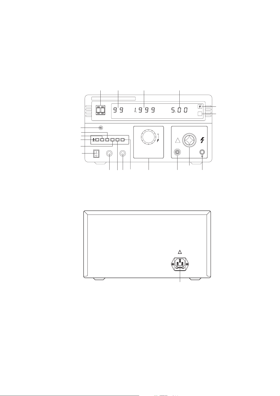
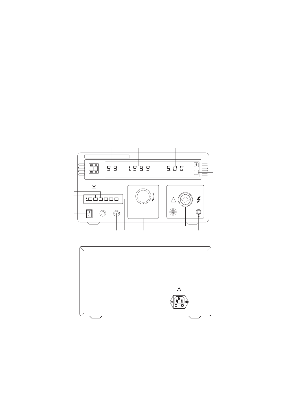
1 Power switch to control all power supply
2 START switch when press down the button instrument will renew to
waiting-test status with the light working.
3 RESET SWITCH press down the button means no HV output
4 Manual port remote control test port
5 V-ADJ rotary switch adjust test voltage
6 HVOUT port test voltage output 1 port for AC test instrument and 2ports
for AC/DC test instrument
7 GND connect with one port of the tested
8 OVER LEAK. indicator “OVER LEAK.” Indication light and annunciate
work when test current leakage exceed pre-set value, voltage output will be
cut off, then press down the REST button and Anti-clockwisely circumvolve
“V-ADJ” rotary switch to the maximum to be ready for next test operation.
9 VOLTAGE meter Three bits digital voltage meter, indicate output voltage
value
10 CURRENT meter 3 1/2 digital current meter, indicate leakage current
value
11 TIMER meter 2 bits digital displayer show timing value
12 TIMER rotary switch to adjust to set timing range
13 OVER LEAK. pre-set adjustor Press down PRE-SET TEST switch to
pre-set leakage current value and display current test result
14 PRESET / TEST button Press down to preset and or else to test
15 CURRENTLEAK. range Testrangeare0~2mA&2~20mA.
2

()"”: ( )
()"”:
()"”:
。:
()"”:
() :
16 CURRENT LEAK. switch Test range is 100mA 200mA .
17 TIMER / MANUAL button Press down to be timing test or else to be
manual test
18 AC/ DC converting button Press down to be DC model or else to be AC
model (CAUTION only for AC/DC instrument)
19 Voltage output convert buttton
20 Power plug AC 220V plug with inner fuse
FRONT AND BEHIND PANELFRONT AND BEHIND PANEL
UBEONLY WITH A 220V FUSE
AC220V 50 60Hz/
!
3
/()TIMER s
LEAK
OVER NG.
TEST
/ ( )VOLTAGE kV
/ ( )LEAKAGE CURRENT mA
VADJ-VADJ-
/MAX
MIN
HV OUT
CONTROL
1
25
6
7
10
8
11
13 12
14
9
99
T-ADJ
!
OFF
ON
POWER
STARTUP RESET
PRE ADJ-
34
15
18
16
17
19
20
21

() :
() "":""
() :
()"":"" " "
,""
()"":""" "
() "
"
.(,
)
() ,
() :
::, :,
:。
:
:
.""
.
.:“”.
.& :"/" ""
.
1 CONNECT POWER Insure “V-ADJ” rotary has to be set at “0”Position and
then turn on power
2 Set LEAK. CURRENT value Press down button 15 adjust current leakage
preset adjustor “14” to preset needed value
3 Connect test port According to the request of tested object, connect test wire
with test object well.
4 TIMER Press timing button 17 to the TIMER position adjust timing
rotary switch to set timing range then press down STARTUP button and
adjust “V-ADJ” rotary switch to needed voltage output
5 CONTRAL Set timing switch 18 to manual position, then press down
“STARTUP” button.
6 In test process, instrument annunciator will work to when test over leakage
current exceeded the pre-set over leakage current, then press down “RESET”
button to waiting test status If take the manual control to test the STARTUP
button should be Unlocked
7 If test over leakage current is less than pre-set value unless time is up or
press down “RESET” button ,instrument will be in the waiting test status.
8 Remote controller test Insert the five-pin plug of remote controller bar to
instrument relevant plug, then press down the switch of test bar to start to test.
Caution: Timing function is no of effect when remote control function working
at the same time.
Test example:
condition test voltage AC 3000V max over leakage current AC 1.5mA
timing rage 30 s
Model RK2672AM voltage withstand test instrument.
Steps
1 Check instrument's V-ADJ rotary switch to be the anti-clockwise end position
2 Plug power wire and then turn on power button
3 Select proper range set voltage range at 5kV position
4 Select proper AC DC voltage range set the AC DC switch at Ac test
position
V operation、V operation、
4

.:
“”
.:""
"", " "
.:"/ " ""
“”
.
.、(
().
.
.“”,
“”
.
12." " :
.
5 Select proper over leakage current range set the over leakage current range at
2 mA position
6 Pre-set over leakage current value press down over leakage current preset
switch to PRESET position then adjust over leakage current preset switch
to 1.500 mA Insure the switch to jump up and be in “TEST”position.
7 TIMER reset set TIMER MANUAL switch to be at TIMER position and
adjust timing rotary switch at 30 seconds range.
8 Insert HV test bar to AC voltage output port, and another black pothook connect
with black GND port of instrument.
9 Connect HV test bar GND wire and tested instrument the style to connect is
the black clamp connecting with GND port of tested power, HV port connecting
with another port L or N The tested must be put on insulationWorktable
10 Startup to test after confirming instrument setting and connection
11 Press down STARTUP button adjust “V-ADJ” rotary switch to increase
voltage until voltage meter show 3.00 kV. If tested leakage current exceed
pre-set value with voltage upgrading, annunciator will indicate and voltage
output stop, it means the tested is not passed , press down “RESET” button to
recover to origin status, or instrument will
REMOTE mode operation insert the aviation five-pin plug of test bar to
remote test port, press down the switch of test bar all time to start test, then
release to reset . Instrument will automatically reset if over leakage current
take place.
13 CAUTION: Timer is disabled if test bar is working ,it is also same to use
out-control instrument' self-service brake switch .
5

VI Principle diagram..VI Principle diagram..
()
()
()
()
()
1 remote test bar 1 piece
2 test wire 1 piece
3 user manual 1 piece
4 certificate 1 shee
5 dust shield 1 piece t
VII Others.、VII Others.、
Power supply Voltage adjustor
Display Main control board
HV convertor
Sampling rectify
Leakage current test DC output
The tested AC output
STARTUP RESET
GND+12V
6

7
SHENZHEN MEIRUIKEELECTRONICTECHNOLOGY CO, . L T DMANUFACTURING
:,..
,, ,,
:
::
h:
:@
ADD 5FlOORQINGCHANGTAI INDUSTRIALGARDEN NO 365
SILIANRKAD HENGGANGTOWN LONGGANGREGION SHENZHEN
CHINA
POSTALCODE518115
TEL. 0755 - 83987768 FAX0755-82736668
ttp //www.chinarek.com
Email chinarek 126.com
SHENZHEN MEIRUIKE ELECTRONIC TECHNOLOGY CO,.LTD
MODEL SERIES CODE
PURCHASE DATE USE DATE
DEPARTMENT CONTACTOR
POST CODETEL.
ADDRESS
PROBLEMDESCRIPTION:
REPAIRRECORD:
VIII Maintenance card、VIII Maintenance card、(
)
cut down along the dashed and post to our
Corporation
This manual suits for next models
8
Table of contents
Other MEIRUIKE Test Equipment manuals