Bender UNIMET 800ST User manual

Manual
EN
UNIMET8xxST_D00008_01_M_XXEN/02.2016
UNIMET® 800ST/UNIMET® 810ST
Test system for electrical safety
Software version: from 3.1.9

Bender GmbH & Co. KG
P.O. Box 1161 • 35301 Gruenberg • Germany
Londorfer Straße 65 • 35305 Gruenberg • Germany
Tel.: +49 6401 807-0 • Fax: +49 6401 807-259
© Bender GmbH & Co. KG
All rights reserved.
Reprinting only with permission
of the publisher.
Subject to change!
Photos: Bender archives.

3
Table of Contents
UNIMET8xxST_D00008_01_M_XXEN/02.2016
1. How to get the most out of this manual ............................................................. 7
1.1 About this operating manual .............................................................................................. 7
1.2 Technical support .................................................................................................................... 7
1.3 Explanation of symbols and notes ..................................................................................... 8
2. Safety instructions .................................................................................................. 9
2.1 Delivery ........................................................................................................................................ 9
2.2 Intended use .............................................................................................................................. 9
2.3 Qualified personnel ................................................................................................................. 9
2.4 General safety instructions ................................................................................................ 10
2.5 Delivery conditions, warranty and liability .................................................................. 10
3. System description .............................................................................................. 11
3.1 Areas of application ............................................................................................................. 11
3.2 Versions UNIMET® 800ST and UNIMET® 810ST ........................................................... 11
3.3 Functional description ........................................................................................................ 12
3.4 Standard-compliant tests .................................................................................................. 13
3.5 System components ............................................................................................................15
3.6 Operating elements ............................................................................................................. 16
4. Quick reference guide ......................................................................................... 17
5. Operation and setting ......................................................................................... 21
5.1 Commissioning ...................................................................................................................... 21
5.1.1 The touchscreen .................................................................................................................... 22
5.1.2 Connecting a printer ............................................................................................................ 22
5.1.3 Print setup in PDF file .......................................................................................................... 22
5.1.4 Connecting an external keyboard .................................................................................. 23
5.1.5 Connecting barcode scanner ........................................................................................... 23
5.1.6 Connecting USB stick ........................................................................................................... 23
5.1.7 TP1010 for tests according to DIN EN 61010-1 (VDE0411-1):2011-07 ............... 23
5.1.8 Other device settings .......................................................................................................... 24
5.2 Principle of operation .......................................................................................................... 24
5.2.1 Menu bar .................................................................................................................................. 24

Table of Contents
4UNIMET8xxST_D00008_01_M_XXEN/02.2016
5.2.1.1 The "Action" menu ......................................................................................................... 24
5.2.1.2 The "View" menu ............................................................................................................. 25
5.2.1.3 The "?" menu ..................................................................................................................... 25
5.2.2 Main window ........................................................................................................................... 25
5.2.3 The software keyboard ........................................................................................................ 26
5.2.3.1 Entries via the keyboard ............................................................................................... 26
5.2.3.2 Selection from a list ........................................................................................................ 26
5.2.4 Saving settings or cancelling ............................................................................................. 27
5.2.5 Toolbar ...................................................................................................................................... 28
5.2.5.1 How to use the context menu when only one entry is activated ................. 28
5.2.5.2 How to use the context menu if more than one entry is activated .............. 29
5.2.5.3 How to use the query filter .......................................................................................... 30
5.3 Main folder ............................................................................................................................... 31
5.4 Test engineer names ............................................................................................................ 32
5.4.1 Log in test engineer .............................................................................................................. 32
5.4.2 Test engineer names administration .............................................................................. 32
5.4.2.1 Other options for "Log in test engineer" ................................................................ 32
5.4.2.2 Logging in, changing or deleting test engineers ................................................ 33
5.4.2.3 Creating a new test engineer ..................................................................................... 33
5.5 Device settings ....................................................................................................................... 34
5.5.1 Windows system control .....................................................................................................34
5.5.1.1 Saving settings ................................................................................................................. 34
5.5.1.2 Display ................................................................................................................................ 34
5.5.1.3 Printer .................................................................................................................................. 34
5.5.1.4 Date/time ........................................................................................................................... 35
5.5.1.5 Regional settings ............................................................................................................ 35
5.5.1.6 Stylus ................................................................................................................................... 35
5.5.1.7 Input panel ........................................................................................................................ 35
5.5.1.8 Keyboard ............................................................................................................................ 35
5.5.1.9 Keyboard layout .............................................................................................................. 35
5.5.1.10 Volume & sound .............................................................................................................. 35
5.5.2 Zero balance PE resistance (test probe/measuring lead) ....................................... 36
5.5.3 Nominal voltage ..................................................................................................................... 36
5.5.4 Database ................................................................................................................................... 37
5.5.5 Backup (USB) ........................................................................................................................... 37
5.5.6 Remote control RS-232 ........................................................................................................ 37
5.5.7 Diagnostic ................................................................................................................................ 38
6. Testing and measuring ....................................................................................... 39
6.1 Test concept ............................................................................................................................ 39

Table of Contents
5
UNIMET8xxST_D00008_01_M_XXEN/02.2016
6.2 Classification ........................................................................................................................... 40
6.2.1 General ...................................................................................................................................... 40
6.2.2 Method of measurement ................................................................................................... 41
6.2.3 Applied part ............................................................................................................................ 41
6.2.4 Equipment type ..................................................................................................................... 42
6.2.5 Extras ......................................................................................................................................... 42
6.2.6 Test sequence ......................................................................................................................... 43
6.2.7 Visual inspection ................................................................................................................... 44
6.2.8 Functional test ....................................................................................................................... 45
6.2.9 Exiting classification ............................................................................................................. 47
6.3 Device test ............................................................................................................................... 48
6.3.1 Connecting the DUT ............................................................................................................ 50
6.3.2 Carrying out the visual inspection .................................................................................. 51
6.3.3 Carrying out the electrical test steps ............................................................................. 51
6.3.3.1 PE conductor test ........................................................................................................... 52
6.3.3.2 Switching on the DUT ................................................................................................... 53
6.3.4 Carrying out the functional test ...................................................................................... 54
6.3.5 Evaluating and documenting the test result .............................................................. 55
6.3.5.1 Client administration ....................................................................................................56
6.4 Importing test data .............................................................................................................. 57
6.5 The "Test specifications" folder ........................................................................................ 58
6.5.1 How to access the "Test specifications" folder ........................................................... 58
6.5.2 How to start a device test from the "Test specifications" folder .......................... 58
6.5.3 Editing, printing, exporting and deleting a test specification .............................. 58
6.5.3.1 Test step editor ............................................................................................................... 60
6.6 The "Device protocols" folder ........................................................................................... 62
6.6.1 How to access the "Device protocols" folder" ............................................................ 62
6.6.2 How to start a device test from the "Device protocols" folder ............................. 62
6.6.3 Editing, printing, exporting and deleting a device protocol ................................. 62
6.7 Single test ................................................................................................................................ 64
6.7.1 How to access the "Single test" folder ........................................................................... 64
6.7.2 How to start a single test .................................................................................................... 64
6.7.3 Using the query filter ........................................................................................................... 64
6.7.4 Protective earth resistance measurement ................................................................... 64
6.7.4.1 Differentiating between the types of protective earth resistance
measurement .................................................................................................................. 65
7. Maintenance and calibration ............................................................................. 67
7.1 Calibration ............................................................................................................................... 67
7.2 Changing the battery .......................................................................................................... 67
7.3 Maintenance ........................................................................................................................... 67

Table of Contents
6UNIMET8xxST_D00008_01_M_XXEN/02.2016
7.4 Cleaning and care .................................................................................................................. 67
7.5 Device error ............................................................................................................................. 67
8. Data ......................................................................................................................... 69
8.1 Standards .................................................................................................................................. 69
8.1.1 Application standards .......................................................................................................... 69
8.1.2 Design standards ................................................................................................................... 69
8.2 Terms and abbreviations .................................................................................................... 70
8.2.1 Terms used ............................................................................................................................... 70
8.2.2 Abbreviations used ............................................................................................................... 71
8.3 Test steps .................................................................................................................................. 73
8.4 Technical data ......................................................................................................................... 90
8.5 Ordering information ........................................................................................................... 92
INDEX ...........................................................................................................................95

7
UNIMET8xxST_D00008_01_M_XXEN/02.2016
1. How to get the most out of this manual
1.1 About this operating manual
This operating manual describes the test systems UNIMET® 800ST and UNIMET® 810ST with the soft-
ware version indicated on the cover page. The functions and processes described may vary from
those featured in other versions. It is designed for electrically skilled persons working in electrical en-
gineering and electronics.
Please read this operating manual before using the devices. This documentation must be kept in an
easily accessible location near to the device.
This manual has been compiled with great care. It may nevertheless contain errors and mistakes. The
Bender Group cannot accept any liability for injury to persons or damage to property resulting from
errors or mistakes in this manual.
Each of the registered trademarks which appears in this document remains the property of its owner.
For improved readability, the test systems UNIMET® 800ST and UNIMET® 810ST will also be referred
to as "UNIMET®".
1.2 Technical support
As a Bender customer, you will receive technical support and assistance in the event of queries relat-
ing to equipment you have purchased. Please contact the Technical Sales Department or our Service
Department:
Service hotline: 0700-BenderHelp (telephone and fax)
Carl-Benz-Straße 8 • 35305 Gruenberg • Germany
Tel: +49 6401 807-760 • Fax: +49 6401 807-629
E-mail: info@bender-service.com • www.bender.de
How to get the most out of this manual
8UNIMET8xxST_D00008_01_M_XXEN/02.2016
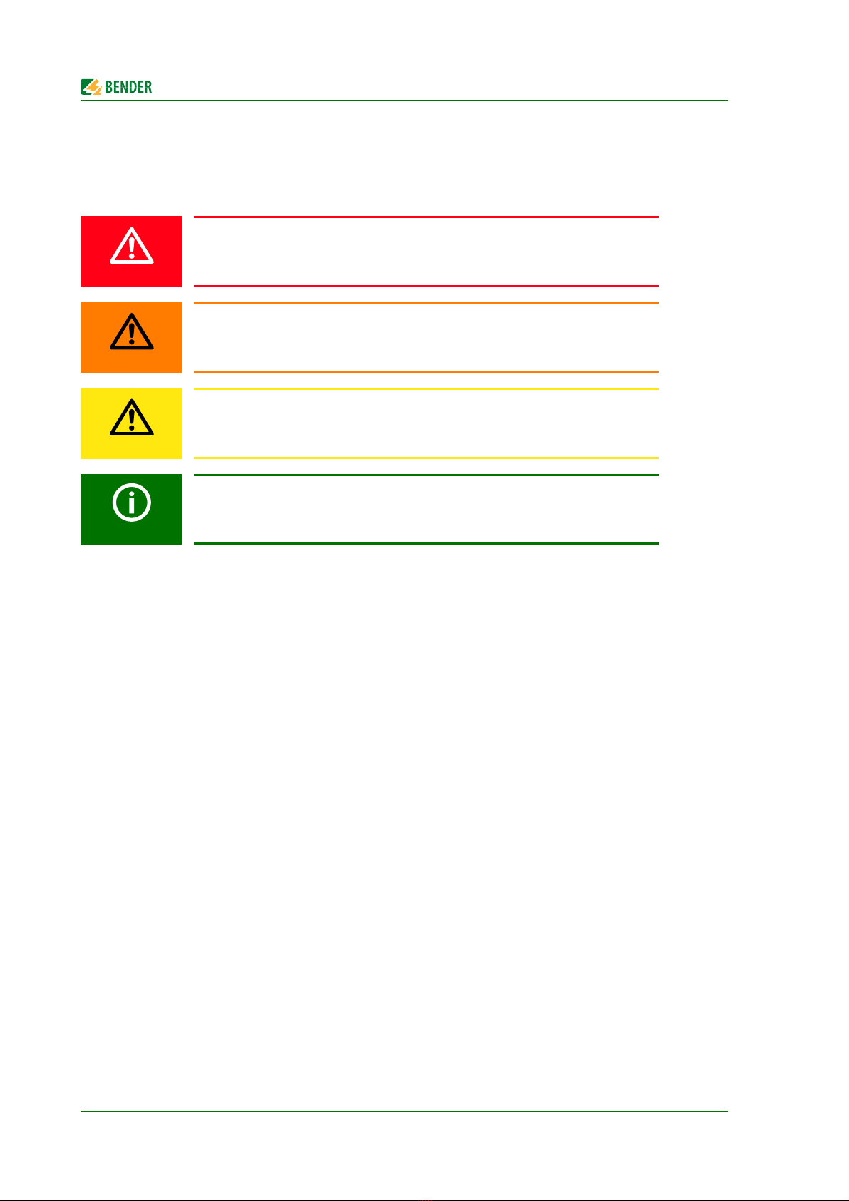
1.3 Explanation of symbols and notes
The following terms and symbols are used to denote hazards and instructions in Bender documen-
tation:
The signal word indicates that there is a high risk of danger, that will result in
death or serious injury if not avoided.
This signal word indicates a medium risk of danger that can lead to death or se-
rious injury, if not avoided.
This signal word indicates a low-level risk, that can result in minor or moder-
ate injury or damage to property, if not avoided.
This symbol denotes information intended to assist the user in making optimum
use of the product.
DANGER
WARNING
CAUTION

9
UNIMET8xxST_D00008_01_M_XXEN/02.2016
2. Safety instructions
2.1 Delivery
Inspect the dispatch and equipment packaging for damage, and compare the contents of the pack-
age with the delivery documents. Devices damaged in transit must not be used. In the event of dam-
age in transit, please contact Bender immediately.
Equipment may only be stored in areas where it is protected against dust, damp, spray water and
dripping water and where the specified storage temperatures can be assured.
The selling company's "General conditions of sale and delivery" always apply.
2.2 Intended use
The test systems are exclusively intended for the area of use stipulated in the chapter "System de-
scription" on page 11.
Intended use also implies:
Observance of all instructions in this operating manual and
compliance with any test intervals.
Any other use than that described in this manual is regarded as improper. The Bender Group cannot
accept any liability for damage resulting from such use.
2.3 Qualified personnel
Only appropriately qualified personnel may work with the Bender devices. Personnel who are famil-
iar with the installation, commissioning and operation of the equipment and have undergone ap-
propriate training are considered qualified. The personnel must have read this manual and
understood all instructions relating to safety.
Bender would be happy to provide training in respect of the use of test equipment. Training for two
people is included in the purchase price of the test system. You can find the current dates on our
homepage http://www.bender.de -> Know-how-> Seminars.
Risk of destruction due to incorrect mains voltage
The UNIMET® 800ST or 810ST must always be connected to the supply voltage
(AC 100…120 V, AC 220…240 V) indicated on the nameplate. Only these two
voltage ranges are permissible. Voltages between these two voltage ranges are
not permissible!
Failure to observe this requirement may damage the test system and any device
under test connected to it.
CAUTION

Safety instructions
10 UNIMET8xxST_D00008_01_M_XXEN/02.2016
2.4 General safety instructions
Bender devices are designed and built in accordance with the state of the art and accepted rules in
respect of technical safety. However, the use of such devices may introduce risks to life and limb of
the user or third parties and/or result in damage to Bender devices or other property.
Use Bender devices only:
–Asintended
– In perfect working order
– In compliance with the relevant safety regulations and safety standards applicable at the
location.
Eliminate all faults immediately which may endanger safety.
Do not make any unauthorised changes.
Use only accessories (e.g. measuring cables, adapters, etc.) or replacement parts purchased
from or recommended by the manufacturer of the devices. Failure to observe this requirement
can result in fire, electric shock and injury.
Reference signs must always be clearly legible. Replace damaged or illegible signs immediately.
2.5 Delivery conditions, warranty and liability
The conditions of sale and delivery set out by Bender apply.
For software products, the "Softwareklausel zur Überlassung von Standard-Software als Teil von
Lieferungen, Ergänzung und Änderung der Allgemeinen Lieferbedingungen für Erzeugnisse und
Leistungen der Elektroindustrie" (software clause in respect of the licensing of standard software as
part of deliveries, modifications and changes to general delivery conditions for products and servic-
es in the electrical industry) set out by the ZVEI (Zentralverband Elektrotechnik- und Elektronikindus-
trie e.V., the German Electrical and Electronic Manufacturers' association) also applies.
Delivery and payment conditions along with a copy of the software clause can be obtained from
Bender in printed or electronic format.
.

11
UNIMET8xxST_D00008_01_M_XXEN/02.2016
3. System description
3.1 Areas of application
The UNIMET® is used to test electrical safety. It has been designed for following areas of application:
Testing medical electrical equipment in accordance with DIN EN 60601-1 (VDE 0750-1):2013-12
(optional software licence required for IEC 60601-1).
Recurrent tests and testing prior to first use of medical electrical equipment or systems in
accordance with DIN EN 62353 (VDE 0751-1).
Testing electrical equipment for measurement, control and laboratory use in accordance with
DIN EN 61010-1 (VDE 0411-1):2011-07 (optional software licence for IEC 61010-1 as well as test
probe TP1010 required).
Recurrent tests of hospital and care beds.
Single-phase electrical equipment: "Prüfung nach Instandsetzung, Änderung elektrischer
Geräte - Wiederholungsprüfung elektrischer Geräte" (Inspection after repair, modification of
electrical appliances and periodic inspection on electrical appliances) acc. to DIN VDE 0701-
0702; VDE 0701-0702:2008-06.
In conjunction with a DS32A adapter, the electrical safety of three-phase devices with a current
input of up to 32 A can be tested acc. to IEC 62353 (VDE 0751-1) and DIN VDE 0701-0702 . Tests
are always carried out during operation using the differential measurement method.
3.2 Versions UNIMET® 800ST and UNIMET® 810ST
The difference between the hardware of the UNIMET® 810ST and its predecessor UNIMET® 800ST is
an even more efficient PC module.
If the corresponding software licence has been purchased, the operating software enables addition-
al tests according to IEC 60601-1 (med. electrical equipment) or DIN EN 61010-1 (electrical equip-
ment for laboratory use).
The operating software indicated on the cover page can be used with the UNIMET® 810ST, but also
with the existing UNIMET® 800ST. In this case, the following restrictions apply:
UNIMET® has been designed solely for use with earthed systems. If the test system
is used other than as intended, i.e. on an IT system, the measured values of any
leakage currents will not be reproducible. The test result cannot be used.
Art. no. of the
UNIMET® 800ST Restrictions
B 9602 8010
B 9602 8014, B 9602 8016
B 9602 8017, B 9602 8018
No restriction of the range of functions. Software licences for DIN EN
60601-1 and DIN EN 61010-1 can be installed.
B 9602 8000
B 9602 8004, B 9602 8006
B 9602 8007, B 9602 8008
Software licences for DIN EN 60601-1 and DIN EN 61010-1 cannot be
installed.

System description
12 UNIMET8xxST_D00008_01_M_XXEN/02.2016
3.3 Functional description
The test system supplies measurement results and evaluates them immediately in order to classify
the test as "PASSED" or "FAILED". In addition to the electrical test steps, the test specification, which
follows classification, contains a visual inspection and a functional test. The test specification is saved
in the "Test specifications" folder. The test sequence can be completed automatically, semi-automat-
ically or manually dependent upon the DUT.
The test results can be displayed on the screen, saved or printed out using an external printer. The
test results can be stored as PDF file and saved to a USB drive (USB stick) for any subsequent print-
outs.
In the event of unexpected results, the DUT can be inspected in more detail by carrying out a single
test. Tested devices can be saved under their device IDs in the "Device protocols" folder. The data
memory provides space for up to 10000 data records. Device IDs may only appear more than once if
they are assigned to different clients.
The date of the last test and the test interval are saved. If a device passes the test, the test date is up-
dated by the set test interval. Filter and sort functions (query filter) make selecting test data easy.
Test specifications and device protocols can be transferred to a PC software program (e.g.
UNIMET® 800ST Control Center) via the RS-232 interface or using a USB drive (USB stick). For recur-
rent tests, the data stored in the PC software are transferred back to the UNIMET®.
The RS-232 interface is also used for any subsequent updates of the internal operating software on
the test system.
The "Test engineer catalogue" folder can be beneficial if more than one person is working with the test
system. Test engineers already registered on the system are simply selected from this folder. There is
no need to re-enter the name of the test engineer. The "Test engineer names", "Test specifications" and
"Device protocols" folders share the same data memory. Accordingly, the number of test engineer
names is limited only by the size of the available memory.
The large colour display is backlit. Graphics illustrate how to connect the DUT. Operation is quick and
easy via the touchscreen. A standard keyboard (PS/2 or USB) can also be connected.
System description
13
UNIMET8xxST_D00008_01_M_XXEN/02.2016
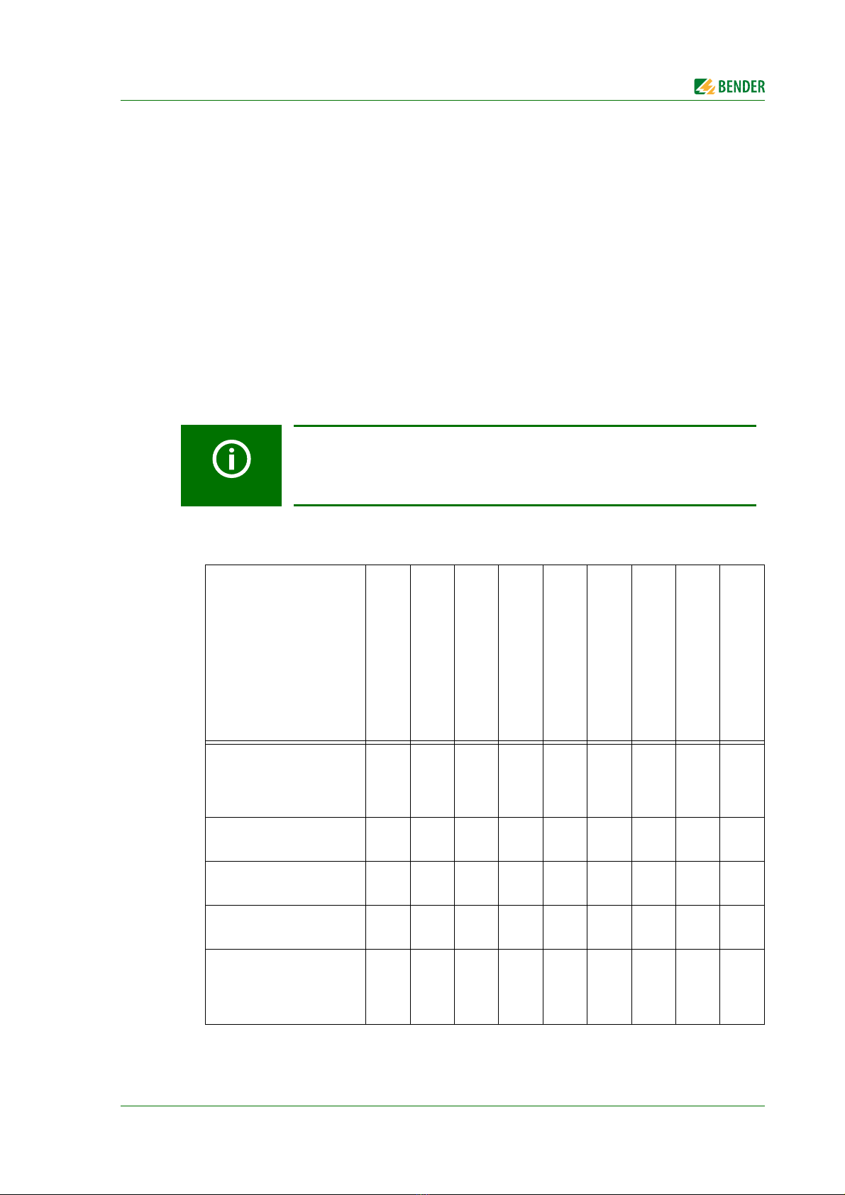
3.4 Standard-compliant tests
The UNIMET® carries out measurements and tests according to the following standards (see also
chapter "8.1 Standards"):
Medical electrical equipment -Part 1: General requirements for safety.
Test in compliance with DIN EN 60601-1 (VDE 0750-1); optional software licence required for
IEC 60601-1.
Medical electrical equipment, recurrent tests in accordance with DIN EN 62353 (VDE 0751-1).
Prüfung nach Instandsetzung, Änderung elektrischer Geräte - Wiederholungsprüfung elek-
trischer Geräte (Inspection after repair, modification of electrical appliances and periodic
inspection on electrical appliances) acc. to DIN VDE 0701-0702; VDE 0701-0702:2008-06.
Electrical equipment for measurement, control and laboratory use - Part 1: General require-
ments
Test according to DIN EN 61010-1 (VDE 0411-1): optional software licence for IEC 61010-1 as
well as test probe TP1010 required.
The UNIMET® carries out the following measurements and tests:
Depending on the national language selected for the user interface, the appro-
priate standard appears on the display and the device protocol. Example:
German: DIN EN 62353 (VDE 0751-1)
English or other languages: IEC 62353
Measurement
DIN EN 60601-1
(VDE 0750-1)
DIN EN 62353
(VDE 0751-1)
DIN VDE 0701-0702
DIN EN 61010-1
(VDE 0411-1)
Direct measurement method
Differential measurement
method
r.m.s.
(root mean square value)
AC
DC
PE resistance
(permanently installed
and transportable
equipment)
XXXX X
InsuIation resistance
(Class I and Class II) XXX X
InsuIation resistance
(applied part – PE) XX
InsuIation resistance
(applied part- LN) XX
Equipment leakage
current - alternative
method
(Class I and Class II)
XX X

System description
14 UNIMET8xxST_D00008_01_M_XXEN/02.2016
Applied part leakage
current - alternative
method
XX
Equipment leakage
current
(Class I and Class II)
X XXX
PE current X XXX
Earth leakage current XXX
Touch current X XXXXX
Touch voltage XXX
Applied part leakage
current XXX
Patient auxiliary current XXX
Total applied part leakage
current XXX
Applied part leakage
current with mains
voltage on applied part
XX X
Mains voltage XXXX X
Current consumption XXXX X
Apparent power XXXX X
Supply cable test X
Measurement
DIN EN 60601-1
(VDE 0750-1)
DIN EN 62353
(VDE 0751-1)
DIN VDE 0701-0702
DIN EN 61010-1
(VDE 0411-1)
Direct measurement method
Differential measurement
method
r.m.s.
(root mean square value)
AC
DC
System description
15
UNIMET8xxST_D00008_01_M_XXEN/02.2016
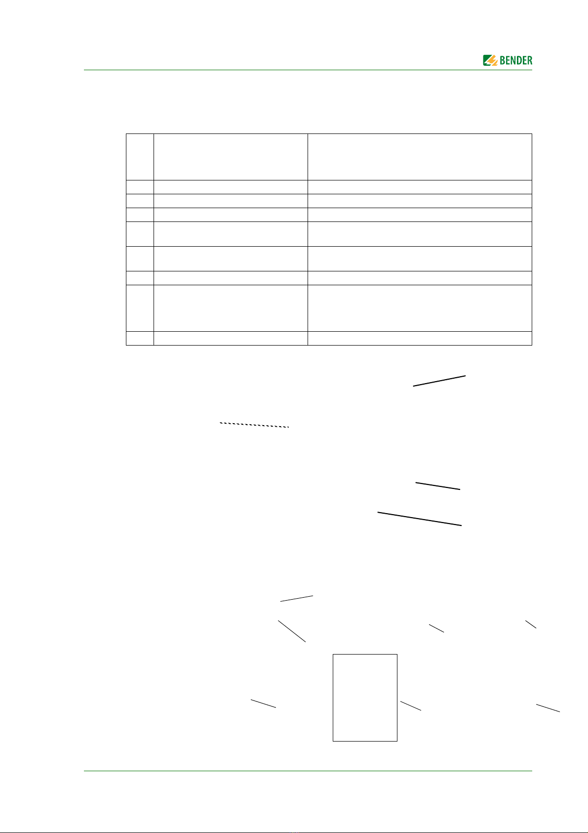
3.5 System components
The following accessories are supplied with the UNIMET® test system:
1 Carryingbag
For storage and transport of the test system and its accesso-
ries. Accessories are kept in the side pocket (1a) and the
inside pocket (1b). There is a loop to hold the stylus pen (1c)
supplied with the system for operating the touchscreen.
2 Test terminal (safety claw grip) For connection to accessible parts of the DUT
3 Test probe, single-pole For testing accessible parts of the DUT
4 Measuring lead, single-pole For testing permanently installed equipment
5 VK701-7 Adapter for non-heating
appliances
For testing device connecting cables
6 Interface cable (null modem cable) Enables data to be exchanged between the test system
and a PC (RS-232 interface)
7 Calibration certificate
Proof of the calibration work carried out in the factory
8 Technical manual and software tools
on CD. The CD is kept in the inside
pocket (1b).
- Manual of the test system
- Software for saving test specifications and device proto-
cols on a PC, software to transfer firmware updates to
the UNIMET
Power supply cord, detachable For connection to the supply voltage (no picture)
1
1B
1a
6
3
8
7
245
1c

System description
16 UNIMET8xxST_D00008_01_M_XXEN/02.2016
3.6 Operating elements
1 Touchscreen for operator control and indication. For this purpose, a stylus is included in the scope of
supply.
2 Durable plastic enclosure, with pushbuttons for safe storage in the carrying bag.
3 10 sockets (1…10) for the connection of patient electrodes.
4 Measuring terminals
- [B] (violet) for the connection of the single-pole test probe supplied with the product.
- [A] for active test probe TP800 with pushbutton (option).
- Socket [C] for equipotential bonding (e.g. connection for single-pole line extension with clip for the test-
ing of permanently installed equipment).
- Socket [D] for functional earth
5 Test socket: This is where the DUT's power supply cable is plugged in.
6 Connection to the supply voltage and power switch with thermo-magnetic circuit-breaker.
7 Connection for the external 25 A power source EPS800.
Note: The connector will lock into position and is protected against being pulled out unintentionally.
The plug can only be removed after pushing the movable grip back.
8Interfaces:
- PS/2 Connection for external keyboard
- RS-485 Serial interface for Bender Service
- RS-232 interface, 9-pin, electrically isolated, for connection to a PC
- USB interface for connection to a printer, a USB stick, an external keyboard or a barcode scan-
ner (2 x host) and a PC (1 x device, for Bender Service only)
- Ethernet Network connection (optional)
543
18
7
6
2

17
UNIMET8xxST_D00008_01_M_XXEN/02.2016
4. Quick reference guide
Switching on the test system
Selecting a test specification
There are three options, dependent upon the starting point:
The "Quick reference guide" chapter provides a brief overview of how the test sys-
tem works. We strongly recommend that you read the entire manual in order to
ensure that you can use all the functions of the test system.
Actions Details Page
1. Switch on the power switch 21
2. Select a test engineer 32
3. If you are switching the test system on
for the first time: Connect and configure
the accessories you need.
- Connect the printer
- Connect an external keyboard
- Connect barcode scanner
- Calibrate test probe or measuring lead if
necessary
22
23
23
36
Starting point Actions Page
The DUT is new:
Start the classification by selecting the appli-
cable test standard.
1. Select the applicable test standard.
2. Make the settings.
3.
Click to save (and test
)
18, 40
The DUT has previously been tested (recurrent
test):
The DUT is listed in the "Device protocol"
folder under its "Device ID.
1. Open the "Device protocols" folder.
2. Select the "Device ID".
3. Start the test with .
62
You know the type of the DUT:
The "Name" of the test specification" appears
in the "Test specifications" folder.
1. Open the "Test specifications" folder.
2. Select the "Name" of the test specifica-
tion.
3. Start the test with .
58
CAUTION
OK

Quick reference guide
18 UNIMET8xxST_D00008_01_M_XXEN/02.2016
Classification of a new DUT
There is not yet a test specification available for the DUT. The required test steps are identified by
means of classification.
Actions Details Page
1. Select the applicable test standard. 40
2. Select the applicable protection class. 40
3. Enter a name (type name) for the new
test specification.
Then open each tab in turn and make
the settings.
Click to complete the settings proc-
ess.
40
4. Click "Saving and testing" to save the
test specification and to start the test.
Click "Save" to save the test specifica-
tion without starting the test.
47
OK

Quick reference guide
19
UNIMET8xxST_D00008_01_M_XXEN/02.2016
Performing the test
To start a test (initial test), proceed as follows:
►After classification, select "Saving and testing",
►Select an existing test specification in the "Test specifications" folder and then click on the
"Measuring device" icon
►or call up "Start device test" from the context menu.
To start a recurrent test, proceed as follows:
►Select an existing device protocol in the "Device protocols" folder, then
– click on the "Measuring device" icon
– or call up "Start device test" from the context menu.
Actions Details Page
1. Connect the DUT, then click "Start". 48
2. Perform a visual inspection:
- Check that the information displayed
is applicable and check or uncheck
the boxes as appropriate.
- Click "Proceed" to carry out further
visual inspections.
- Click "Complete" to save and quit the
visual inspection process.
51
3. Perform the electrical test steps:
The test steps are carried out in
sequence with
- the DUT switched off
- the DUT switched on
- the DUT switched on and
the phase reversed.
51
4. Perform a functional test:
- answer the questions or
enter measured values as appropriate.
- Click "Proceed" to carry out further
functional tests.
- Click "Complete" to save and quit
the functional test process.
54

This manual suits for next models
11
Table of contents
Other Bender Test Equipment manuals


