Page 3
Configuration
Power On Options
HART MODE, AUTO OFF & BACKLIGHT
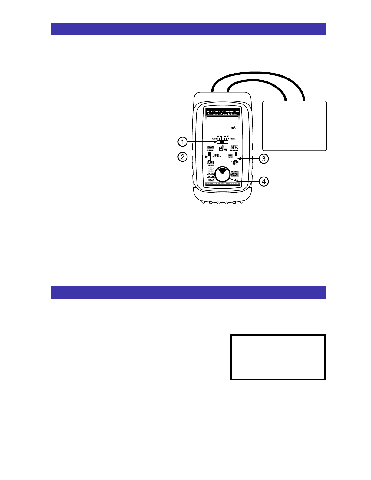
Move q POWER SWITCH to “mA”, “% 4 to 20
mA” or “READ VDC”.
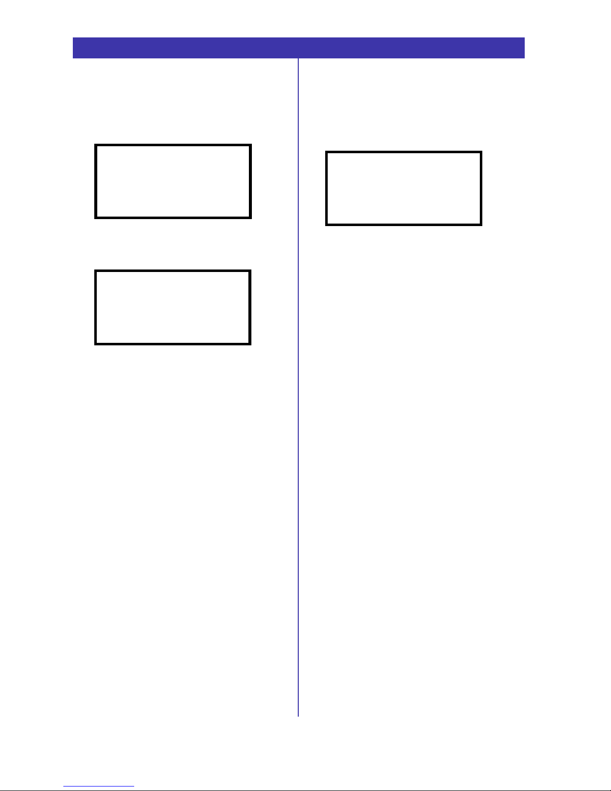
The following display will appear for 3 seconds:
Press the rDIAL KNOB on while this screen is
displayed for basic setup options. The following
display will appear for 30 seconds:
Turn the rDIAL KNOB to move through the
menu. Press the rDIAL KNOB to toggle
between OFF and ON. These settings are
remembered even with the power off.
EXIT MENU - exits this menu immediately and
saves any changes. Menu will automatically exit
after 30 seconds of inactivity.
HART MODE - when ON a 250 Ohm resistor is
automatically inserted in series with the output.
This allows a HART Communicator to
communicate with a HART Transmitter without
adding an external resistor in the loop.
AUTO OFF - If AUTO OFF is ON, the unit will
turn off after 30 minutes of inactivity to save
battery life. If AUTO OFF is OFF the unit will stay
on until the POWER SWITCH is moved to the off
position.
BACKLIGHT - If BACKLIGHT is ON the
backlight will light all the time the unit is powered
up. For maximum battery life turn the backlight
off when using the 334Plus in areas with enough
ambient light to read the display.
Note: All settings are remembered even with the
power off. Removing the batteries resets the
values to factory defaults.
PRESS AND HOLD
EZ-DIAL
TO ENTER
SETUP MENU
> EXIT MENU
HART MODE OFF
AUTO OFF OFF
BACKLIGHT OFF
Advanced Options
STEPS, RAMP & GROUND LEAK DETECTION
Setup
Double click the rDIAL KNOB at any time the
unit is on and the following display will appear
for 30 seconds:
Turn the rDIAL KNOB to move through the
menu. Press the rDIAL KNOB to toggle
between OFF and ON or to change the steps
setting. These settings are remembered even
with the power off.
EXIT MENU - exits this menu immediately and
saves any changes. Menu will automatically exit
after 30 seconds of inactivity.
STEPS - pressing the knob will cycle from 2, 3,
5 steps and RAMP.
2 steps will automatically switch between 4 &
20 mA (0 & 100%).
3 steps between 4, 12 & 20 mA (0, 50 &
100%).
5 steps between 4, 8, 12, 16 & 20 mA (0, 25,
50, 75 & 100%).
RAMP will continuously ramp the output
between 4 & 20 mA (0 & 100%).
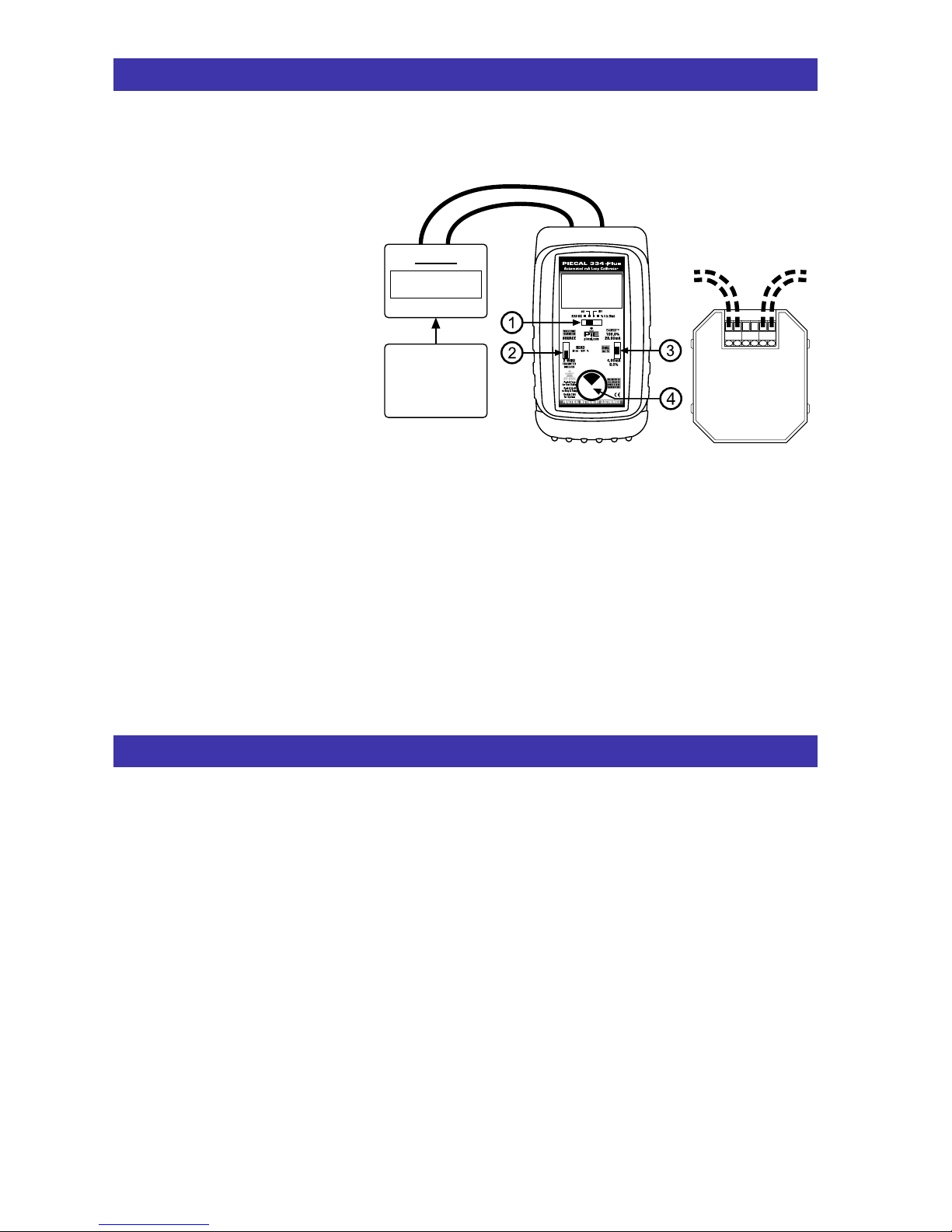
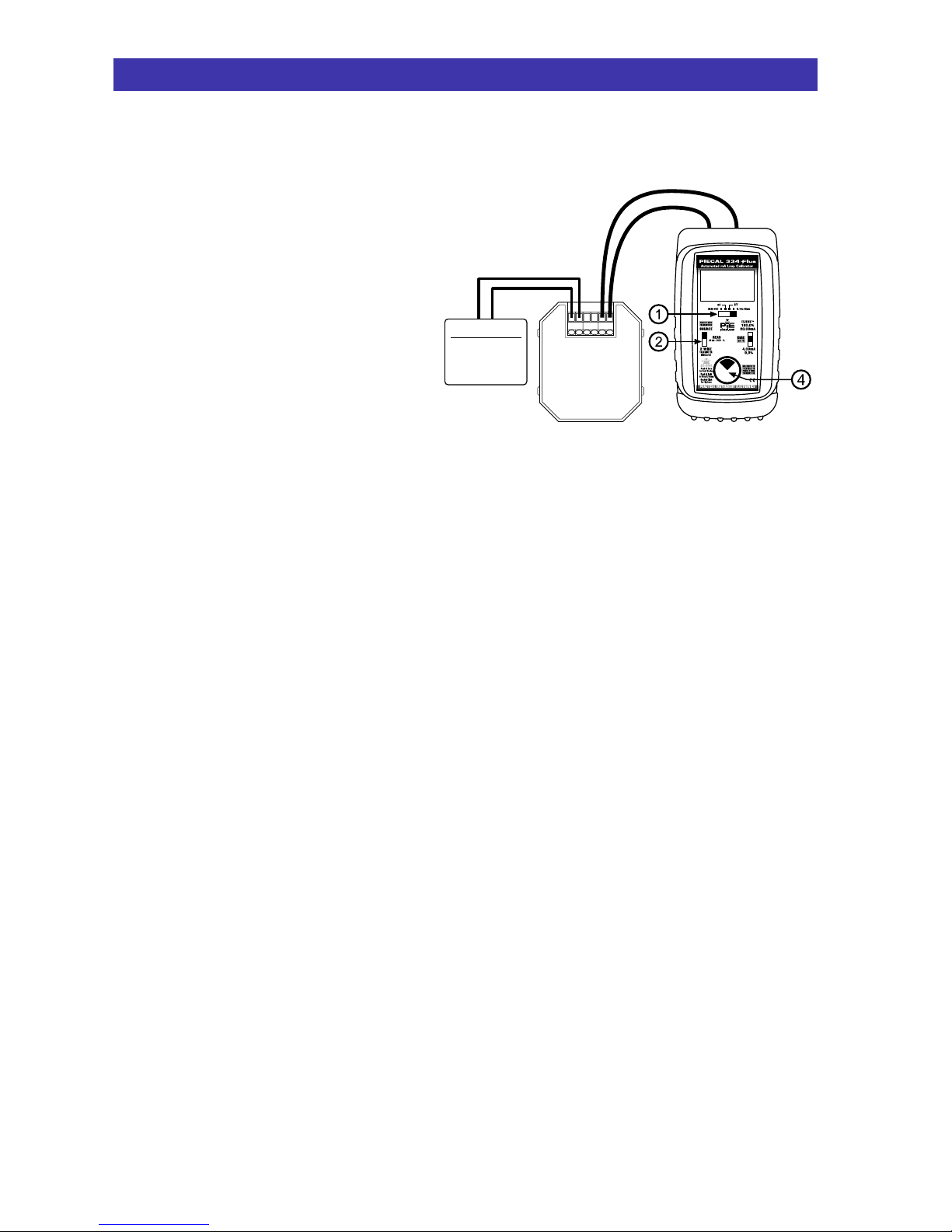
GROUND LEAK DETECTION - when ON the
334Plus has the ability to check for current leaks
caused by ground faults, moisture or corrosion.
This operates in Power/Measure mode while
powering up a 2-wire transmitter or loop.
Note: All settings are remembered even with the
power off. Removing the batteries resets the
values to factory defaults.
> EXIT MENU
STEPS 5
GND LEAK DET OFF
Test Equipment Depot - 800.517.8431 - 99 Washington Street Melrose, MA 02176
TestEquipmentDepot.com