MEIRUIKE RK9950 Series User manual

RK9950 series program-controlled leakage current test instruction manual
MEIRUIKE INSTRUMENT
Manual
RK9950 series
Program controlled leakage current tester
Instruction manual
Shenzhen Meiruike Electronic Technology
Co., Ltd.

RK9950 series program-controlled leakage current test instruction manual
Version history:
Due to the possible errors or omissions in the manual, improvement and perfection of
instrument functions, updating of technology and upgrading of software, the manual will be
adjusted and revised accordingly and continuously improved for the convenience of use.
Please pay attention to the software version and manual version.
October 2020.........................................Vision 1
Statement: the company may improve and improve the performance, function, software,
structure, appearance, accessories, packaging and instruction manual of the product.
Any modification is subject to no further notice!
If in doubt, please contact us.

RK9950 series program-controlled leakage current test instruction manual
Contents
Chapter 1 Safety Rules................................................................................................................... 1
1.1 General Provisions.................................................................................................................1
1.2 Maintenance......................................................................................................................... 1
1.3 Test environment...................................................................................................................2
1.3.1 Working position........................................................................................................ 2
1.3.2 Input power................................................................................................................2
1.3.3 workplace................................................................................................................... 3
1.4 Operator Regulations............................................................................................................ 3
1.4.1 Operator Qualification............................................................................................... 3
1.4.2 Safety rules.................................................................................................................3
1.4.3 Clothing regulations................................................................................................... 3
1.4.4 Medical regulations....................................................................................................3
1.5 Safety grounding regulations................................................................................................ 4
1.6 Regulations on fuse replacement......................................................................................... 4
1.7 Test safety regulations...........................................................................................................4
1.8 Test exception provisions...................................................................................................... 4
1.9 Safety points..........................................................................................................................5
Chapter 2 Overview and technical indicators..................................................................................... 5
2.1 Product Overview..................................................................................................................5
2.2 Technical Indicators............................................................................................................... 7
Chapter 3 Front and back panel description................................................................................... 9
3.1 Front panel structure............................................................................................................ 9
3.1.1 Schematic diagram of front panel..............................................................................9
3.1.2 front panel description.............................................................................................. 9
3.1.3 Description of indication function area................................................................... 11
3.1.4 Parameter function area description.......................................................................11
3.2 Rear panel structure............................................................................................................12
3.2.1 Schematic diagram of rear panel.............................................................................12
3.2.2 Rear panel description............................................................................................. 12
3.3 Screen display area definition.............................................................................................13
3.3.1 Measurement display page area..............................................................................13
3.3.2 File domain...............................................................................................................14
3.3.3 Soft key area.............................................................................................................14
3.3.4 Display area of measurement results...................................................................... 14
3.3.5 Parameter setting area.............................................................................................14
3.3.6 System settings.........................................................................................................14
3.3.7 Time display area..................................................................................................... 14
3.4 Main menu buttons and corresponding displayed pages.................................................. 14
3.4.1 Main menu button of measurement display...........................................................14
3.4.2 Main menu button of parameter setting.................................................................15
3.4.3 system setting main menu button...........................................................................15

RK9950 series program-controlled leakage current test instruction manual
3.4.4 Main menu button of file management.................................................................. 16
Chapter 4 Operating Instructions......................................................................................................16
4.1 Boot instructions and boot screen......................................................................................16
4.2 Operation steps................................................................................................................... 17
4.2.1 Setting tester parameters........................................................................................ 17
4.2.2 Connect the tester to the object............................................................................. 17
4.2.3 Press the "start" button to start the test.................................................................18
4.2.4 determination of qualified products....................................................................... 18
4.2.5 determination of unqualified products................................................................... 18
4.2.6 Operation instructions of START and STOP.......................................................... 19
Chapter 5 PLC remote control interface........................................................................................... 19
Chapter 6 Parameter setting............................................................................................................. 20
6.1 Instrument power on self test............................................................................................ 20
6.2 Parameter setting mode..................................................................................................... 22
6.3 Parameter setting description.............................................................................................25
6.4 System settings parameter description.............................................................................. 31
6.5 Description of document parameters.................................................................................33
Chapter 7 Remote control.................................................................................................................34
7.1 RS232C interface description.............................................................................................. 34
7.2 RS485 / 232C interface description.................................................................................... 35
7.3 USBTMC remote control system......................................................................................... 36
Chapter 8 SCPI serial port instruction reference.............................................................................. 36
8.1 Brief description of instruction format:..............................................................................36
8.2 SCPI instruction set............................................................................................................. 37
8.3 DISPLAY subsystem command set.......................................................................................37
8.4 FUNCtion subsystem command set.................................................................................... 38
Chapter 9 Maintenance guide...........................................................................................................47
9.1 Daily maintenance...............................................................................................................47
9.2 Simple troubleshooting.......................................................................................................48
9.3 Software upgrade steps of instrument system...................................................................48

RK9950 series program-controlled leakage current test instruction manual
1
Chapter 1 Safety Rules
The contents of the manual are subject to change without prior notice
Please contact our company directly if there is anything unknown in the manual
Regulations and matters needing attention before testing!
Warning: to prevent failure or damage to the tester, please use the tester within
the specified voltage range.
1.1 General Provisions
Before using the tester, please read the manual carefully to understand the operation procedures
and relevant safety signs to ensure safety.
Before turning on the input power switch, please select the correct input voltage specification.
Chassis earthing symbol
Warning: it should be noted that the operation,
application or condition carried out is highly dangerous,
which may lead to personal injury or death.
The current generated by the tester is enough to cause casualties. In order to prevent accidental
injury or death, when moving and using the tester, please observe clearly before operating.
1.2 Maintenance
1.2.1 in order to prevent electric shock, non professionals should not open the cover of the tester.
All parts inside the tester should not be replaced without permission. If the tester is abnormal,
please ask our company or the designated dealer for help.

RK9950 series program-controlled leakage current test instruction manual
2
1.2.2 regular maintenance
The tester, power line, test line and related accessories should be carefully inspected and
calibrated at least once a year to ensure the safety of operators and the accuracy of the tester.
1.2.3 user modification
The user is not allowed to change the circuit or parts of the tester by himself, otherwise the
warranty of our company will be invalid and we will not be responsible for the consequences.
1.3 Test environment
1.3.1 Working position
When operating the tester, it must be ensured that the tester is placed in a place that ordinary
personnel cannot touch at will. If it cannot be done because of the arrangement of the
production line, the test area must be isolated from other facilities and specially marked with
"test work area".
1.3.2 Input power
The tester uses single-phase power supply of 220 V / 110 V and 50 Hz / 60 Hz. Before turning on
the power switch, please ensure whether the power supply voltage meets the requirements.
The test area power supply must have a separate switch, installed at the entrance of the test area,
to ensure that all personnel can identify. In case of emergency, turn off the power immediately.
In order to prevent the tester from failure, please use it within
the specified voltage range.

RK9950 series program-controlled leakage current test instruction manual
3
1.3.3 workplace
Use non-conductive material as much as possible. The test site must be kept neat and clean
at all times, and no disorder is allowed. Please put the unused tester and test line in a fixed
position, so that all personnel can immediately distinguish the tested object, the object to be
tested and the object to be tested.
The air in and around the test area shall not contain combustible gas, and the tester shall
not be used beside combustible materials.
1.4 Operator Regulations
1.4.1 Operator Qualification
The output current of the tester is enough to cause personal injury or death in case of
electric shock due to wrong operation, so it must be used and operated by trained and qualified
personnel.
1.4.2 Safety rules
Operators must give education and training at any time to make them understand the
importance of various operation rules, and operate the tester according to the safety rules, so as
to ensure the safety of the tester.
In order to prevent the occurrence of electric shock accidents, please wear insulating gloves
before using the tester.
1.4.3 Clothing regulations
Operators are not allowed to wear metal ornamented clothes or metal hand ornaments and
watches. These metal ornaments are easy to cause accidental electric shock.
When you get an electric shock, the consequences will be even more serious.
1.4.4 Medical regulations
The tester must not be operated by people with heart disease or wearing a heart rate
regulator.

RK9950 series program-controlled leakage current test instruction manual
4
Incorrect grounding or ungrounded may lead to electric shock accident.
1.5 Safety grounding regulations
The tester must be well grounded, and the ground wire must be well grounded before the test
to ensure the safety of the operator. If the ground connection on the power plug is not reliable,
an additional protective ground terminal is provided on the back panel of the tester to connect to
the safe ground.
Incorrect grounding or ungrounded may lead to electric shock accident.
1.6 Regulations on fuse replacement
Please turn off the input power switch and disconnect the power plug
before replacing the fuse,the Standard Fuse (100v-120v 47hz-63hz 3.15a; 200v-240v 47hz-63hz
5a) should be replaced.To avoid electric shock, be sure to replace the fuse after disconnecting the
power cord.
1.7 Test safety regulations
After connecting the test line to the object to be tested, the connection shall be reliable. The
operator must make sure that the switch and remote control switch can be operated completely
independently and can not be controlled by other personnel. When the remote control switch is
not in use, it should be placed in a fixed position and can not be placed at will.
Never use a tester on a live circuit board or equipment! Do not touch the
test object or the object connected with the test object during the test!
1.8 Test exception provisions

RK9950 series program-controlled leakage current test instruction manual
5
Under some specific conditions, the tester will not respond to the reset key, the test time
value will not move, and the display will be black screen, which is very dangerous. When these
situations occur, please be sure to turn off the power switch and disconnect the power plug, do
not use, please contact our company.
When the test is abnormal, turn off the power switch immediately
and unplug the power plug!
1.9 Safety points
■Unqualified operators and irrelevant personnel should stay away from the test area.
■The test area must be kept in a safe and orderly state at all times.
■During the test, it is not allowed to touch the test object or any object connected with
the tested object.
■In case of any problem, please turn off the output and input power immediately.
Chapter 2 Overview and technical indicators
2.1 Product Overview
Thank you for purchasing and using our products. Before using this instrument, please confirm it
according to the "accessories" in the last chapter of this manual,
If there is any discrepancy, please contact us as soon as possible to protect your rights and
interests.
2.1.1 Program controlled leakage current tester is 5 inch TFT LCD display, the tester uses 32 bit
high-speed MCU and large scale digital circuit design.
Built in GB9706.1-2007 (IEC60601-1:1998) body impedance simulation network, the card card
MD network interface contains MD-A (coincidence GB/T12113-2003 、GB4793.1-2007) 、
MD-B( GB/T12113-2003、GB4793.1-2007、GB4706.1-2005、

RK9950 series program-controlled leakage current test instruction manual
6
GB4943.1-2011、GB8898-2011 、GB7000.1-2015)、MD-C( GB/T12113-2003、GB7000.1-2015)、
MD-D(GB4793.1-2007)、MD-E( GB4943.1-2011、GB4793.1-2007)、MD-F( GB7000.1-2015).
Load voltage and current overrun protection; MD network multiple fast protection, safe and
reliable. Dynamic and static two power test states; leakage current test automatically switches L
(phase line) and N (zero line). Its setting and operation are very simple, and provides PLC remote
control interface, RS232C, RS485, USB and other interfaces, which is convenient for users to
quickly combine into a comprehensive test system.
2.1.2 The tester has the functions of unqualified identification, sound and light alarm and
automatic control of test time, which can meet the needs of production line or quality inspection.
2.1.3 The tester can be used for leakage current test of household appliances, electronic
instruments, electronic equipment, electric tools, electric heating appliances, etc.
2.1.4 Service conditions
Power supply voltage: 110V / 220V (±10%)
Power frequency: 50 Hz / 60 Hz (±5%)
2.1.5 Ambient temperature and humidity
Normal working temperature: 0 ℃- 40 ℃, humidity: < 90% RH
Measuring environment temperature: 20 ℃± 8℃, humidity: < 80% RH
Transportation environment temperature: 0 ℃- 55 ℃, humidity: ≤93% RH
2.1.6 Preheating
Preheating time after startup: ≥30 minutes
2.1.7 Insulation resistance
Under metering working conditions, the insulation resistance between the power terminal and
the shell shall not be less than 50m Ω.
Under the condition of hot and humid transportation, the insulation resistance between the
power terminal and the shell shall not be less than 2m Ω.
2.1.8 Insulation strength
Under the metering working conditions, the power supply terminal and the shell can withstand
the rated voltage of 1.5kV and frequency of 50 Hz AC power supply for 1 minute without

RK9950 series program-controlled leakage current test instruction manual
7
breakdown and flashover.
2.1.9 Electromagnetic compatibility and compliance standards
The transient sensitivity of the power supply is GB6833.4. Conduction sensitivity is GB6833.6.
Radiation interference is required according to GB6833.10.
Standard for household electrical appliances (IEC60335, GB4706.1-2005) and luminaire standard
(IEC60598-1-1999,GB7000.1-2007),information standard(GB8898-2011, GB12113 ,
GB4943.1-2011, IEC60065, IEC60590) and so on.
2.2 Technical Indicators
1、Specific parameters
Model
RK9950(Passive)
RK9950A(500VA)
RK9950B(1000VA)
RK9950C
Basic
functions
Screen size
5-inch TFT LCD screen
Number key
Parameter setting digital input
Coding switch
Parameter selection and confirmation function
Up, down, left and
right
function keys
Parameter setting up and down selection function
LOCK keyboard
locking function
Prevent accidental modification of test conditions or prohibit modification of test conditions
Alarm function
Voice alarm
Communication
interface
RS232C、RS485、USB
USB interface
Copy, copy and storage functions
Control interface
HANDLER(PLC)
Test method
Dynamic, static
Load
voltage(AC)
Range
0-300V
Accuracy
+ (2% ×display value +0.5V)
Frequency
50/60Hz
RK9950 series program-controlled leakage current test instruction manual
8
Load
current(AC)
Maximum
25A
Over
current
protection
Sound and light alarm, cut off the load output
Leakage
current
setting
Upper limit setting
Range
0.001-20.00mA
Resolution
<10mA,0.001/step >10mA,0.01mA/step
Lower limit setting
Range
0.000-20.00mA
Resolution
<10mA,0.001/step >10mA,0.01mA/step
Explanation
The lower limit is set to 0 without judgment
Leakage
current
measureme
nt
Range and accuracy
0.001-0.050mA DC-10KHz
±(5% ×display value + 5 words)
0.050-20.00mA DC-10KHz
±(2% ×display value + 2 words)
0.050-20.00mA
10KHz-1MHz
±(5% ×display value + 5 words)
MD
simulated
human
network
8 standard
networks
MD-A(GB/T12113-2003 、GB4793.1-2007) 、MD-B B1(GB/T12113-2003 、GB4793.1-2007 、
GB4706.1-2005、GB4943.1-2011、GB8898-2011、GB7000.1-2015)、MD-C(GB/T12113-2003、
GB7000.1-2015)、MD-D(GB4793.1-2007)、MD-E(GB4943.1-2011、GB4793.1-2007)、
MD-F(IEC60598-1:2014 、GB4793.1-2007) 、MD-G(GB4943.1-2011 、IEC60950-1:2005 、
GB4793.1-2007、IEC61010-1:2001)
Test time
Range
Single timing test: 0.1-999s ±1%; closing time is continuous test
Explanation
When setting 0S test, only N-wire is tested,no L conversion
Output
power
Passive
500VA
1000VA
Three phase
passive
External
power
supply
External connection
Built in
Built in
External
connection
2、General technical index
General technical index
Working temperature and
humidity
0℃-40℃,≦75%RH
Power Supply
100V-121V,198V-242V,47.5-63Hz 5A 250V
RK9950 series program-controlled leakage current test instruction manual
9
Chapter 3 Front and back panel description
3.1 Front panel structure
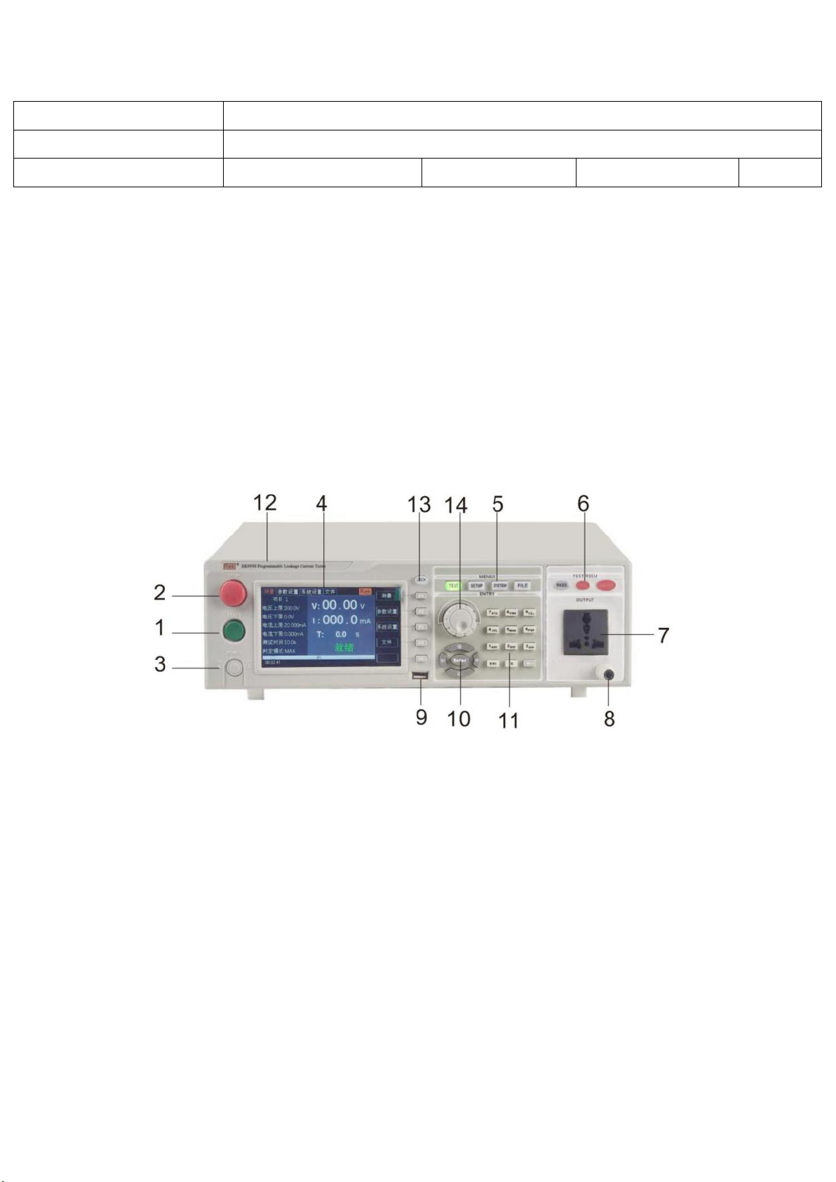
3.1.1 Schematic diagram of front panel
3.1.2 front panel description
1. start key (START)
The green instantaneous contact switch has the following functions:
Start switch for testing voltage output
2.reset key (STOP)
The red instantaneous contact switch has the following functions:
Fuse size
5A 250V 10A 110V
External volume(D×H×W)
430mm×105mm×350mm
Weight
13KG
16KG
18KG
14KG

RK9950 series program-controlled leakage current test instruction manual
10
In the setting mode, it acts as a switch to leave the setting mode.
When testing, it can be used as a switch to interrupt the test.
At the end of the test, it is used as a switch to exit the test and enter the next state to be tested.
3. Power switch
Working power input of tester
4. LCD screen
Display various setting information and test data.
5. Function area
Operation area of various settings
6. Test result indication area
When the tester outputs current, the indicator light will be on, indicating that "there is current
output, under test", indicating that the test has passed and failed.
7. Output terminal
Test the output voltage of the tested part
8. Ground return terminal
As the loop grounding terminal of the tested part. Suitable for two core power plug without
ground wire.
9. USB storage area
As the interface of file data copy and copy.
10. up and down, left and right, and ENTER confirm key.
It is used to adjust the options when setting the parameter function. Enter is the confirmation
function key.
11. 0-9 number pad
Enter the numeric value of the parameter

RK9950 series program-controlled leakage current test instruction manual
11
12. Tester model indication
13. LOCK lock key
It is used to press the panel function keys, and light up and lock the panel functions during the
test, except stop and start keys.
14. Rotary encoder potentiometer
For parameter setting, you can adjust the potentiometer and press the key to confirm the setting.
3.1.3 Description of indication function area
1. Qualified lamp
It contains green LED indicator light, which will be on when the object to be tested passes the
test.
2. Unqualified lamp
It contains red LED indicator light, which will be on when the test fails.
2. When the light is on, it means that the instrument should pay attention to safety
during the test.
3.1.4 Parameter function area description
Key is the function of test status, select this key to enter the test; key is the
parameter setting key, select this key to enter the test parameter setting of the tester;
Key is the function setting key of the tester system. Select this key to set various
functions of the tester system;
Key is the function key of tester file. Select this key to copy, copy and delete the test data
file.

RK9950 series program-controlled leakage current test instruction manual
12
3.2 Rear panel structure
3.2.1 Schematic diagram of rear panel
3.2.2 Rear panel description
1. Power socket
The standard input power socket provides working power for the tester. Pay attention to turn off
the input power switch and disconnect the power plug before replacing the fuse, and replace the
Standard Fuse (3.15A/250VAC, 5A / 110VAC).
2. 115V / 230V power conversion
3. Ground terminal
The safety grounding terminal of the tester must be properly grounded to ensure the safety of
the operator.
4. PLC signal terminal
A standard 9-core D-type female terminal block provides remote control monitoring and control
signal interface.
5. RS232C interface
RS232C serial communication function is provided

RK9950 series program-controlled leakage current test instruction manual
13
6. RS485 interface
Provide RS485 serial communication function
7. USB interface
Provide USB computer to connect U disk function
8. AC source input
L、N single phase AC source input.
9. Name plate
Tester model name, date of manufacture and serial number.
3.3 Screen display area definition
RK9950 uses 480 * 272 LCD 5 inch display. The contents displayed in the display are divided into
the following display areas.
3.3.1 Measurement display page area
This area indicates the measurement parameter name of the current page.

RK9950 series program-controlled leakage current test instruction manual
14
3.3.2 File domain
Move the cursor to this area for file management. File management includes loading, saving and
deleting.
3.3.3 Soft key area
This area is used to display the function definition of the soft key. The definition of soft key has
different function definition according to the location of the cursor area.
3.3.4 Display area of measurement results
This area displays test result information and current test conditions.
3.3.5 Parameter setting area
This area displays the parameter settings
3.3.6 System settings
This area displays the parameter settings of the system.
3.3.7 Time display area
This area displays the current working time.
3.4 Main menu buttons and corresponding displayed pages
3.4.1 Main menu button of measurement display
Used for all kinds of measurement and display the home page. The function pages of this part
include (use the "soft key" to select the following page functions, the same below):
Measurement display
Measurement setup
System settings
Document management

RK9950 series program-controlled leakage current test instruction manual
15
3.4.2 Main menu button of parameter setting
It is mainly used to enter the measurement setting interface corresponding to the measurement
display. The main interfaces are as follows:
3.4.3 system setting main menu button
Used to enter the system settings home page. It is mainly about system settings. The function
pages of this part are as follows:

RK9950 series program-controlled leakage current test instruction manual
16
3.4.4 Main menu button of file management
Used for file management settings.
Chapter 4 Operating Instructions
4.1 Boot instructions and boot screen
Before the power cord plug is connected to the mains, please turn off the input "power
switch", check whether the specification of the fuse is correct, and connect the safety ground
This manual suits for next models
4
Table of contents
Other MEIRUIKE Test Equipment manuals

Popular Test Equipment manuals by other brands


PCB Piezotronics
PCB Piezotronics Y482C15 Installation and operation manual

BGS technic
BGS technic 40105 manual

Rohde & Schwarz
Rohde & Schwarz R&S CMW-KM300 user manual

Omega
Omega CDH-93 instruction sheet

Hella Gutmann
Hella Gutmann CSC-Tool operating instructions

Dostmann Electronic
Dostmann Electronic PH CHECK 5040-0301 Operating instruction


