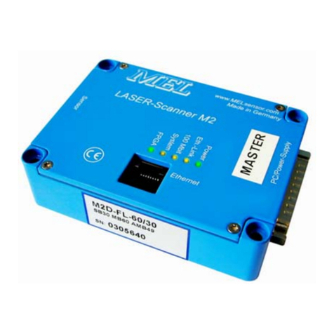
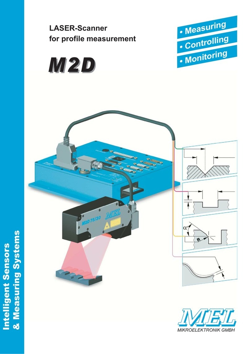
MEL M2-iLAN Series User manual

HB-M2-iLAN-UDP-E.doc page 1 of 44
MEL Mikroelektronik GmbH, Breslauer Str. 2, 85386 Eching / Germany www.MELSensor.de
MIKROELEKTRONIK GMBH Intelligente Sensoren & Mess-Systeme
M2-iLAN
Laser-Scanner
M2D Laser Scanner
with integrated Ethernet-Interface
TCP/UDP
User Manual
MEL Mikroelektronik GmbH
Breslauer Str. 2
D-85386 Eching
Tel. +49 89 / 327 150-0
Fax +49 89 / 319 20 23
www.MELsensor.de March 2010
© Copyright MEL Mikroelektronik GmbH, 2006 ... 2010

M2i-LAN Laser-Scanner manual
HB-M2-iLAN-UDP-E.doc page 2 of 44
MEL Mikroelektronik GmbH, Breslauer Str. 2, 85386 Eching / Germany www.MELSensor.de
Contents
Firmware-Version .........................................................................................................................................................3
System description .......................................................................................................................................................4
Product label.................................................................................................................................................................4
Scanner head and Electronic System...........................................................................................................................4
Connections.......................................................................................................................................................................4
Ethernet Hardware........................................................................................................................................................4
Ethernet cabling............................................................................................................................................................4
Multi-Scanner Arrays ....................................................................................................................................................5
How many Scanners can work in one network segment? ............................................................................................5
Factory default IP address............................................................................................................................................5
Scanner heads..............................................................................................................................................................5
Connectors........................................................................................................................................................................6
Ethernet cable...............................................................................................................................................................6
Control cable.................................................................................................................................................................6
Status LED’s.................................................................................................................................................................6
RJ-45 connector ...........................................................................................................................................................6
Special accessories......................................................................................................................................................7
Technical Data...................................................................................................................................................................8
Integrated electronic system.........................................................................................................................................8
Communication between Electronic system and PC.........................................................................................................9
Task of the Micro controller...........................................................................................................................................9
Task of the PC-Software...............................................................................................................................................9
Communication Components........................................................................................................................................9
Adjustment of Scanners IP-Address.............................................................................................................................9
Resolve IP Address conflicts ......................................................................................................................................10
MEL Configuration Software „EthernetScanner-2008“................................................................................................11
Temporary change of the IP Address .........................................................................................................................11
Temperature monitoring..............................................................................................................................................12
Pixelauslesen : Limit of scanners viewing area...........................................................................................................12
Scanner controls.........................................................................................................................................................13
Control commands......................................................................................................................................................13
Trigger and Synchronisation operating modes ...........................................................................................................13
External Trigger (Hardware-Trigger)...........................................................................................................................13
Synchronization..........................................................................................................................................................13
Ethernet-Trigger..........................................................................................................................................................13
Digital inputs...............................................................................................................................................................13
UDP transmission mode.............................................................................................................................................14
How to set UDP transmission mode...........................................................................................................................14
Data format and interface description.........................................................................................................................15
Frame Format of TCP data transfer from scanner head to electronic unit..................................................................15
Header and payload data............................................................................................................................................15
Encoder Data, FiFO fill status.....................................................................................................................................15
0x21: info telegram: scanner status information .........................................................................................................16
Info Telegram (the scanners answer to the command 0x21)......................................................................................16
Data format: Register addresses, Commands or Data ...............................................................................................16
Scanner controls.........................................................................................................................................................17
Data format.................................................................................................................................................................18
Sync signal and Status info, encoder information (protocol version 3) .......................................................................18
Meaning of the status byte 2 depending from register 0x11 .......................................................................................19
Value = [0]: Sensor temperature.................................................................................................................................19
Value= [1]: Register contents.....................................................................................................................................19
Value = [2, 3]: Version number electronic system and camera..................................................................................19
value = [4, 5, 6, 7, 8] : operating hours counter ..........................................................................................................19
Value = [9, 10, 11]: on counter....................................................................................................................................19
Value = [12]: Digital inputs 1 , 2 + Bit for Sensors with a mirror..................................................................................19
Value = [13]: Laser control Bit 2...9.............................................................................................................................20
Value = [14]: Version number.....................................................................................................................................20
Value = [15 ...31]: not assigned..................................................................................................................................20
Value = [32 ... 63] 32 Byte Eprom Data Register........................................................................................................21
Register 0x1B: Profile peak recognition threshold......................................................................................................21
HDR-shutter control, Register 0x24 (36).....................................................................................................................22
M2DF/LAN-Structure of Image Data...........................................................................................................................22
Read out complete image...........................................................................................................................................23

M2i-LAN Laser-Scanner manual
HB-M2-iLAN-UDP-E.doc page 3 of 44
MEL Mikroelektronik GmbH, Breslauer Str. 2, 85386 Eching / Germany www.MELSensor.de
Synchronization of Sensors........................................................................................................................................23
Trigger Mode ..............................................................................................................................................................23
Calculation of shutter time ..........................................................................................................................................23
Number of pixels, encoder data..................................................................................................................................23
RS-232 Monitoring......................................................................................................................................................23
115.200 Baud .............................................................................................................................................................23
Web-Server.................................................................................................................................................................25
Available Read out Functions.....................................................................................................................................25
How to set the IP address over the Web ....................................................................................................................25
Requirements for connection to scanner ....................................................................................................................26
Updating (Flashing) Firmware.....................................................................................................................................27
Hardware Requirements.............................................................................................................................................27
Software Requirements ..............................................................................................................................................27
Updating (Flashing) procedure ...................................................................................................................................27
Updating (Flashing) over the Ethernet........................................................................................................................28
Trouble Shooting ........................................................................................................................................................29
Example code for Software engineers........................................................................................................................30
Data format for register addresses and commands....................................................................................................30
3. Command: 0x21 (dump).........................................................................................................................................31
example: // read out FiFo status and sensor temperature ..........................................................................................36
Syntax of HDR shutter control ....................................................................................................................................38
Ports...........................................................................................................................................................................38
Ethernet WinSock Implementation..............................................................................................................................39
Example: (“C”) using WinSock and Scanner functions: ............................................................................................. 39
UDP Implementation...................................................................................................................................................41
IP-Programming for UDP-transmission protocol:........................................................................................................41
Maintenance....................................................................................................................................................................43
Laser Safety................................................................................................................................................................43
Laser Power................................................................................................................................................................44
Environment................................................................................................................................................................44
Sunlight.......................................................................................................................................................................44
Water..........................................................................................................................................................................44
Changes and additions...............................................................................................................................................44
F
Fi
ir
rm
mw
wa
ar
re
e-
-V
Ve
er
rs
si
io
on
n
Hardware-Revision 4.0 with M12 connectors
FPGA Firmware-Revision 4.6
Controller Firmware Revision 2.0.59
This manual describes the installation of the scanner hardware and the use of MEL demo and calibration
software. The manual has been changed to the new version of hardware.
With the transit to the revision 4 hardware, the electronic system has been equipped with M12 connectors.
The scanner head is connected to the network with the standard Ethernet M12 connector. The power and
control connector is an M12 connector with 8 pins.
Tipp: default values should be read from the scanner.
after a reset, the scanner restores all values to default.
to read out the default values:
1. send reset command 0x1E
2. request info telegram 0x21
default values could be different from given values in this manual.
relevant is the actual interface description available from MEL.
when you read out default values from the scanner, these may be
the almost recent values.
Laser Safety
Please refer to the Chapter “Laser Safety and Maintenance” to find recommendations and guidelines for
use of controls, adjustments of performance and recommended practice to avoid any hazardous radiation
exposure (page 43). Use of controls or adjustments or performance of procedures other than those
specified herein may result in hazardous radiation exposure.

M2i-LAN Laser-Scanner manual
HB-M2-iLAN-UDP-E.doc page 4 of 44
MEL Mikroelektronik GmbH, Breslauer Str. 2, 85386 Eching / Germany www.MELSensor.de
S
Sy
ys
st
te
em
m
d
de
es
sc
cr
ri
ip
pt
ti
io
on
n
With the new M2-iLAN „Ethernet“-Scanner the electronic system is integrated in the scanner head. The
system has no extra controller box, so it is highly compact, tight and rugged. The scanner head has two
M12 connectors for Ethernet and power supply & controls. Scanner heads designed for welding applications
additionally have water & air cooling fittings.
M2W-iL-models are rated up to 500°C (950° F) environment
temperature with water cooling, up to 150°C (240°F) with air cooling,
dry and clean atmosphere, non corrosive.
P
Pr
ro
od
du
uc
ct
t
l
la
ab
be
el
l
The product label specifies the type of scanner head, the range and
standoff distance and the serial number with production date
(YYYY.MM.XXX) (XXX= Serial number).
S
Sc
ca
an
nn
ne
er
r
h
he
ea
ad
d
a
an
nd
d
E
El
le
ec
ct
tr
ro
on
ni
ic
c
S
Sy
ys
st
te
em
m
The scanner head has a CCD camera, a line laser projector and an electronic system for digitizing the
camera signals. The electronic system sends the camera signal to the electronic system. The camera is
controlled by the automatic control through the electronic system or in external mode by the application
software. Adjustment for shutter time, video gain and laser intensity are made through either automatic or
under “manual” control by the application software.
Connections
E
Et
th
he
er
rn
ne
et
t
H
Ha
ar
rd
dw
wa
ar
re
e
Standard Ethernet components never have shown problems in the data transmission of the Ethernet
scanners. Network connection Rx+, Rx-, Tx+, Tx- is available on a 4-pin M12-connector D-coded according
to standards. The scanner should be connected with shielded Ethernet cables CAT 5e or better. Total cable
length for Ethernet cabling is 200m according to Standard IEE 802.3
We also use Ethernet scanners in the company network without any effect on the daily office work running
through the same network. Use Ethernet switches, hubs are not recommended. When several scanners are
monitored by one PC, the graphic card and CPU must be strong enough to collect all the data provided by
the scanners. When you doubt, that the Scanner does not deliver all images, you should check the image
counter (page 15: register 0x11, status messages.) The image counter number allows sorting images, if
they arrive in wrong order. This may happen accidentally when transmitting profile data over the internet.
E
Et
th
he
er
rn
ne
et
t
c
ca
ab
bl
li
in
ng
g
The Ethernet network connection is
made with M12 connectors, 4 pin D
coded. The control interface is
connected through an 8 pin M12
connector, the pin details are given
on page 6.
Ethernet cables should be double
shielded. The cables should be
according specification CAT 5e or
better.
When the Scanner is connected to
the network over a Ethernet switch,
normal (1:1 wired) patch cable may
be used. When you want to make a
direct connection from the Scanner
to the PC use a cross-wired cable.
Picture at the right side:
Connecting a scanner with switch and PC.

M2i-LAN Laser-Scanner manual
HB-M2-iLAN-UDP-E.doc page 5 of 44
MEL Mikroelektronik GmbH, Breslauer Str. 2, 85386 Eching / Germany www.MELSensor.de
M
Mu
ul
lt
ti
i-
-S
Sc
ca
an
nn
ne
er
r
A
Ar
rr
ra
ay
ys
s
Up to 32 Scanners could be integrated in a network. Normally, you should use a separate network card for
the connections to the scanner(s). The use of a separate network card is optional and depends from your
network settings, network traffic on the dedicated PC and system load. You may use a Ethernet switch, a
Ethernet cable to each scanner and power supply 10 … 28 V DC.
H
Ho
ow
w
m
ma
an
ny
y
S
Sc
ca
an
nn
ne
er
rs
s
c
ca
an
n
w
wo
or
rk
k
i
in
n
o
on
ne
e
n
ne
et
tw
wo
or
rk
k
s
se
eg
gm
me
en
nt
t?
?
The Scanner sends 290 Profile points per Scan with 93.5 Hz :
oTCP-IP Header
oM2DF-LAN-Header
oProfile data
oStatus information
oReserved Bytes for additional data
oadditional Information as Encoder-Data, FiFO
oCRC
Each Profile creates a 2048 Byte Block = 93.4 x 2.048 kBytes / s = 191.28 kByte / s.
The network channel has 100 Mbit = 12.500 kBytes / sec
This will allow theoretically maximum = 12.500 / 191 = 65.4 Scanners.
The numbers of collisions in a network rises, when the network load exceeds 50%. Therefore as a realistic
figure, we assume 50 % of maximum transmission rate.
This leads to the number of 32 Scanners for maximum usage in one network segment.
Segmentation of data blocks
Limitations of the network cards like setting of the MTU (Maximum Transfer Unit), and accordingly load in
the network causes that the 2048 Bytes will not be transferred in one packet, but segmented into two
packets of 1460 k and 588 k. The user must not think about this effect, though the TCP implementation of
the operating systems cares about sorting and reconciling the TCP packets. More likely, the software
engineer designing an application must know this and wait long enough to make sure that all packets have
been received, before using the data.
F
Fa
ac
ct
to
or
ry
y
d
de
ef
fa
au
ul
lt
t
I
IP
P
a
ad
dd
dr
re
es
ss
s
At the end of the manufacturing test the scanners are set to:
IP address 192.168.123.245
Subnet mask 255.255.255.0.
Before you integrate these units in your network, you should set the network address to a working address
which will operate in your network properly. For more technical details and background information see the
network tutorial. The set up procedure is given on page 24.
S
Sc
ca
an
nn
ne
er
r
h
he
ea
ad
ds
s
The scanner head power supply is connected with a 8 pin M12
connector. The control cable has power supply, sync signals, digital
inputs for encoders and control of firmware upload and RS-232 diagnose
interface. The pin definition is given on the next page.
The Ethernet connection is made with a 4 pin M12 connector according
to standard. The Ethernet cable connectors are male.
The connector for the control cable is male. The controls & power cable
has a female connector and at the other end is either with open leads for
clamps or with a male connector.

M2i-LAN Laser-Scanner manual
HB-M2-iLAN-UDP-E.doc page 6 of 44
MEL Mikroelektronik GmbH, Breslauer Str. 2, 85386 Eching / Germany www.MELSensor.de
Connectors
E
Et
th
he
er
rn
ne
et
t
c
ca
ab
bl
le
e
C
Co
on
nt
tr
ro
ol
l
c
ca
ab
bl
le
e
* when connecting the sync output to the command input 1, at start of the sensor (power on), the sensor is brought to
the programming mode. In this programming mode the firmware can be uploaded with the RS-232 connection or over
the Ethernet network.
** when the sync output is connected to the command input 2, at start of the sensor, the sensor will activate the RiP
mode and communicate only at the default IP address.
Please note: when both command inputs were connected to sync out, the sensor will go to the programming mode.
The activation of the Programming mode or RiP mode is made only when the sensor is switched on and had no
power before for a few 10 seconds.
*** colors are given as an example.
Tipp: the Scanner could be connected with one single*, highly flexible, cable for robotic applications. The cable used
is a Ethernet cable specially made for the use with robots. The power supply is taken over two unused wires in the
network cable, following the idea of the IEEE 802.3af standard. Details are given in the TE-M2-iLAN-connection-E.pdf.
Cables following this definition are available from MEL on request.
* single cable attachment: connection with a single cable specified for use with robots.
** PoE: Power over Ethernet, standard IEEE 802.3af.
S
St
ta
at
tu
us
s
L
LE
ED
D’
’s
s
Status LED’s Meaning color*** OK when
Power Power OK Green LED is lit
Eth-Link Ethernet Link in Function Yellow Blinking
100 Mbit Ethernet Link Activity Orange Blinking
System Hardware Self test OK Orange Blinking
FPGA FPGA Self test OK Orange LED is lit
R
RJ
J-
-4
45
5
c
co
on
nn
ne
ec
ct
to
or
r
Pin Signal Connector A Pin “Crossed” B Signal
1 Transmit data + Green +White 1 Red + White Receive data +
2 Transmit data - Green 2 Red Receive data -
3 Receive data + Red + White 3 Green +White Transmit data +
4 Not used - Blue 4 Blue Not used -
5 Not used + Blue + White 5 Blue + White Not used +
6 Receive data - Red 6 Green Transmit data -
7 Not used + Brown+ White 7 Brown+ White Not used +
8 Not used - Brown
Colors are given as
an example.
Cables could have
different colors.
8 Brown Not used -
Tipp: the M12-Ethernet cable has male connectors at both ends. The M12-control cable has either a female
connector at the electronic box and a male connector or open wires at the other end.
Pin-Nr. Signal Colors *** Remarks
1 Tx+ Green+white Transmit data Ethernet +
2 Rx+ Red+white Receive data Ethernet +
3 Tx- Green Transmit data Ethernet -
4 Rx- Red Receive data Ethernet -
Ethernet
M12 round
4-pin
D-coded
female Shield Connect to case!
Pin-Nr. Signal Colors*** Remarks
1 + 24 V DC White Supply for Electronic box
2 Digital input 1 Brown Encoder and command input 1*
3 GND Green Ground
4 Digital input 2 Yellow Encoder and command input 2 **
5 Sync out Grey Sync signal output (Master)
6 Sync in Orange Sync signal input (Slave); Hardware-Trigger
7 TxD Blue Rs-232 Diagnosis out
8 RxD Red RS-232 Programming data input
M12 round
8-pin
A-coded
male
Shield Connect to pin 3 (ground)

M2i-LAN Laser-Scanner manual
HB-M2-iLAN-UDP-E.doc page 7 of 44
MEL Mikroelektronik GmbH, Breslauer Str. 2, 85386 Eching / Germany www.MELSensor.de
S
Sp
pe
ec
ci
ia
al
l
a
ac
cc
ce
es
ss
so
or
ri
ie
es
s
↑M2-RS232-ProgBox
M2-W-iLAN-80/40/55 →
Scanner head with air / water cooling option
Nr Description MEL
Part name
MEL
order
number
1 M2-RS232-Programming Adapter Box
Adapter to RS-232 interface, for Firmware-Upload, power switch and
default-IP- Address. Requires + 24V power supply!
M2-RS232-ProgBox i.550.006
2 Power supply + 24V, for M2-RS232-Box (Pos. 1) Power supply 24V/250 mA i.550.007
3 Connecting cable M12-8 pin; 2.0 m; free leads Ctrl-Cbl-W-M12-o i.550.008
4 Connecting cable M12-8 pin female socket – 8 pin, 0.4 m SKK 215 i.550.009
5 Connection cable M12-4 pin, D-coded connector – 4 pin
D-coded connectors, Length 0.4 m; PTFE SKK 216 i.550.010
6 Adapter M12 – RJ45 straight, with thread M 16x1.5 Eth-Adapter-G-M12 i.550.011
7 Adapter M12 – RJ45 at angle 90°, with thread M 16x1.5 Eth-Adapter-W-M12 i.550.012
8 Connector M12-4pin-D coded; straight, auto-clamps Eth-Con-D-G-M12 i.550.016
9 Connector M12-4pin-D coded; 90° angle, screw on clamps Eth-Con-D-W-M12 i.550.018
10 Connecting cable M12 male – 4 pin; RJ-45; 1 m Eth-Cbl-M-M12-RJ45 i.550.026
11 Connecting cable M12 female – 8 pin at angle 90° - free leads Ctrl-Cbl-8pWW-o i.550.027
12 Adapter for connecting two RJ45 network cables Adaptor-2N-RJ45 i.550.028
13 Network cable RJ-45, 5m 1:1 (patch) Network cable RJ45 i.550.029
14 Cross wired network cable RJ-45, 5 m Crosslink cable RJ45 i.550.030
15 Connector M12 - 4 pin D-coded with screw on clamps Con-M12 4 pin-m-scr i.550.031
16 Cable receptacle 8 pin female with screw on clamps Con-M12 8 pin-w-scr i.550.032
17 Water / air fittings (spare parts) WaAir-Stub i.550.033
18 Ethernet cable; CAT5e, 4-pin, AWG24 flexible; PUR chloride free
blue, shielded, straight connector, M12, D-coded – RJ45, 2m Eth-Cbl-M12-RJ45-2m i.550.041
19 Ethernet cable; CAT5e, 4-pin, AWG24 flexible; PUR chloride free
blue, shielded, straight connector, M12, D-coded – RJ45, 5m Eth-Cbl-M12-RJ45-5m i.550.042
20 Ethernet cable; CAT5e, 4-pin, AWG24 flexible; PUR chloride free
blue, shielded, straight connector, M12, D-coded – RJ45 – open
leads, length = 15m
Eth-Cbl-M12-o-15m i.550.040
21 Connecting cable M12-4pin crossed Ethernet cable with RJ-45
Cable length customer specific EthRJ45-X-Cbl-M12-custom i.550.043

M2i-LAN Laser-Scanner manual
HB-M2-iLAN-UDP-E.doc page 8 of 44
MEL Mikroelektronik GmbH, Breslauer Str. 2, 85386 Eching / Germany www.MELSensor.de
Technical Data
Profiles update rate max. 93.5 Hz
Profile rate, Trigger-Mode approx. 60 Hz
Profile rate, external synchronized max. 93.5 Hz
Stability of time base 100 x 10-6
Min. / Max. Environment temperature min. 0°C (+ 32°F) max. 40°C (+ 95°F)
Min. / Max. Storage temperature min. –30°C (+ 2°F) max. 75°C (+ 167°F)
I
In
nt
te
eg
gr
ra
at
te
ed
d
e
el
le
ec
ct
tr
ro
on
ni
ic
c
s
sy
ys
st
te
em
m
Supply current 120 mA at 24 V; Laser on
Range of supply voltage + 10 ... 30 V DC
Digital inputs Low = 0 ... 2 V High = 5 ... 30 V
Weight 300 g
Dimensions 102 mm x 74 mm x 27,5 mm
Mounting holes for 4 x M5 screw
connections 12 pin round female for Scanner head
M12 - 8 Pin male supply and controls
Synchronization and external Trigger
M12 4 Pin female = Ethernet D coded
RJ-45-Ethernet internal for service
Protection class IP 65
Vibration: the electronic unit has been specially protected against shock and vibration.
Encoder signal connection
Encoder-Data is received at the digital inputs at the control connector. The encoder information is read and
transmitted embedded in the profile information over TCP Ethernet connection. The encoder data is always
in sync to the profile relating to this encoder data.
RS-232 interface for diagnosis and firmware update
Baud rate: Monitoring 115. 200 Baud
Baud rate: Firmware-Update 57.600 Baud
The RS 232 interface does not carry profile data or scanner control information.
Software: the current release of the MEL „EthernerScanner.exe“ Demo- and configuration software is
available as download from MEL FTP-Server: ftp://melsensor.de. Call MEL hotline for further details.

M2i-LAN Laser-Scanner manual
HB-M2-iLAN-UDP-E.doc page 9 of 44
MEL Mikroelektronik GmbH, Breslauer Str. 2, 85386 Eching / Germany www.MELSensor.de
Communication between Electronic system and PC
The micro controller in the electronic system communicates over Ethernet TCP/IP with the PC. The Scanner
head delivers image data to the micro controller and the FPGA in the electronic system.
T
Ta
as
sk
k
o
of
f
t
th
he
e
M
Mi
ic
cr
ro
o
c
co
on
nt
tr
ro
ol
ll
le
er
r
oRead out of the Scanner head
oSend Scann profile data over TCP/IP-Protocol
oReceive commands for the Scanner head with TCP/IP Protocol
oSend commands to the Scanner head
oChange and store the TCP/IP-Address on request
oSend Status information
oRun integrated Web Browser
T
Ta
as
sk
k
o
of
f
t
th
he
e
P
PC
C-
-S
So
of
ft
tw
wa
ar
re
e
oReceive profile data from Scanner
oDecode Pixel image data format (see „Data format“)
oProcess and display scan profile data
oSend commands to the Scanner head
C
Co
om
mm
mu
un
ni
ic
ca
at
ti
io
on
n
C
Co
om
mp
po
on
ne
en
nt
ts
s
TCP Clients and Server are components of the development environment in the software. In the readily
compiled software (*.exe File) these components exist in the form of “ports”. These ports manage data
traffic in and out to the individual elements of the application software.
The Scanner communicates with the outer world using port address, IP address and a valid subnet mask.
A Gateway is ignored, the scanner opens a peer to peer connection. Therefore the set up of these
communication components needs to be complete to allow proper function of the electronic components
and data communication.
The Scanner stores data in FiFo memory, before data is sent out in a package. The transmission protocol is
TCP/IP*.
* UDP firmware version is available on request!
A
Ad
dj
ju
us
st
tm
me
en
nt
t
o
of
f
S
Sc
ca
an
nn
ne
er
rs
s
I
IP
P-
-A
Ad
dd
dr
re
es
ss
s
The Scanners electronic system has a default address as well as a working IP address. The default IP
address is activated, when you set the RiP-Pin. This is done, when you connect the Sync out pin to the D1
pin before starting power. The default IP address is set firmly, and can not be changed by the user.
Before delivery, the scanners were normally set to the working-IP = 192.168.123.245. When another IP
address has been set, either a note in the shipment papers or a label on the electronic box of the scanner
should show the IP address.
When you want to set a new working IP address, use a Web browser and follow the procedure on page 24.
Please note: after transferring the new working IP address to the scanner electronic system, the
electronic system automatically restarts to make the change effective.
The Web Browser will then display a message to make you aware of the change.
When you receive this message connect to the scanner with the new IP address.

M2i-LAN Laser-Scanner manual
HB-M2-iLAN-UDP-E.doc page 10 of 44
MEL Mikroelektronik GmbH, Breslauer Str. 2, 85386 Eching / Germany www.MELSensor.de
R
Re
es
so
ol
lv
ve
e
I
IP
P
A
Ad
dd
dr
re
es
ss
s
c
co
on
nf
fl
li
ic
ct
ts
s
Using the default IP address is meant for communication with one single scanner, for adjustment of a new
working IP address or other service purpose. Using the default IP address for normal operation is not
recommended.
DHCP is not supported. The Scanner must have a fixed IP address, as well as the network card to which
the scanner shall communicate. Scanner and network card must be in the same network segment. This
means, the network address should vary only in the last three digits. Computers in the network must use
unique and different network addresses. When units in the network use the same address, a conflict exists.
The communication in the network could severely have problems, when this happens.
Tipp: label the units when installing different units in a network
take notes and make a plan of the network addresses used in your network.
when a conflict exists, physically disconnect the network cable form different units to find
out the source of conflict. ... only one unit at a time...
example:
Address Scanner 1: 192.168.123.222;
Address Scanner 2: 192.168.123.223;
Address Scanner 3: 192.168.123.224;
Address Scanner 4: 192.168.123.225;
Address Scanner 5: 192.168.123.226;
Address Scanner 6: 192.168.123.227;
Address Scanner 7: 192.168.123.224; // incorrect IP-Address = conflict!
Address Scanner 8: 192.168.123.229;
Address Scanner 9: 192.168.124.228; // different network segment
Address Network card: 192.168.123.199
The subnet mask for all Scanners and the network card = 255.255.255.0
Do not get mixed: a subnet mask 255.255.0.0 may also work. The subnet mask defines the maximum
number of units in your network. When no more than 254 scanners were present in your network, the
subnet mask 255.255.255.0 will be sufficient.
In our example Scanner 7 has been set erroneously to the IP address 192.169.123.224. this address is
already taken from another Scanner – so a conflict exists. The correct IP-address would have been
192.168.123.228.
Scanner 9 is in another subnet (another network segment). For Scanner 9, the network card should be set
to IP address = 192.168.124.10.
Tipp: how to find out the IP address of the scanner?
1. Use any terminal software, connect the RS-232 diagnostic port to Com-port 1 of your PC
2. Read out the information prompt send out at start up of the scanner.
3. For details see page 22.
I
IP
P-
-A
Ad
dd
dr
re
es
ss
s
f
fa
ac
ct
to
or
ry
y
d
de
ef
fa
au
ul
lt
t
oMAC-Address 8 Byte 00-08-DC-00-00-00
oSerial number 3 Byte MM-YY-ZZZ
oScanner-IP 4 Byte 169.254.150.160:3000 = default Address
oSubnet-Mask 4 Byte 255.255.0.0
oGateway IP 4 Byte 169.254.150.1
oTCP Port 2 Byte, integer last Segment of the TCP/IP-Address (for example 3000)
Back ground: the Scanner and the network card in the PC make a “peer to peer” connection. Once the
communication between these two peers has been initiated, no other network device will be allowed to communicate
with the active scanner. This means, the scanner can communicate only with one PC at a time. Besides the
communication over TCP at any time, from any other PC a http request (Web browser) could be made.

M2i-LAN Laser-Scanner manual
HB-M2-iLAN-UDP-E.doc page 11 of 44
MEL Mikroelektronik GmbH, Breslauer Str. 2, 85386 Eching / Germany www.MELSensor.de
M
ME
EL
L
C
Co
on
nf
fi
ig
gu
ur
ra
at
ti
io
on
n
S
So
of
ft
tw
wa
ar
re
e
„
„E
Et
th
he
er
rn
ne
et
tS
Sc
ca
an
nn
ne
er
r-
-2
20
00
08
8“
“
After the Start of the Scanner (switch on power), the configuration of the scanner is loaded from the internal
EPROM to the micro controllers memory. The MEL demo software then shows the following information:
oTCP/IP Address, Port and MAC Address
oIntensity, shutter time, Video gain
oScanner Status, Firmware-Version, Scanner head temperature
The main window of Ethernet-Demo-Software has the elements profile display and tabs for different function
groups. The profile display at the left side can be switched to display one bigger screen or four small
screens simultaneously. The colors of the profiles can be adjusted by defining RGB values in the settings.ini
file. Function groups are selected with the Tabs 1 … 16. The important Tabs are discussed in the following
text. The Tab 1 defines the IP address and assignment of the display window. The window count of the four
windows starts at 0 and counts up to 3. The big window is number 9.
T
Te
em
mp
po
or
ra
ar
ry
y
c
ch
ha
an
ng
ge
e
o
of
f
t
th
he
e
I
IP
P
A
Ad
dd
dr
re
es
ss
s
When you want to set the IP address only for a demonstration double click one of the entries in the Tab 1
and overwrite the IP address for a temporary change. The change will not be stored permanently. When
you restart the application, the previous setting will be read in from the ini file.
To make the IP address change permanent edit the EthernetScanner.ini file.
Tipp: use any Text editor to edit the EthernetScanner.ini File, but be aware: when you destroy
the ini File, the application could have a problem.

M2i-LAN Laser-Scanner manual
HB-M2-iLAN-UDP-E.doc page 12 of 44
MEL Mikroelektronik GmbH, Breslauer Str. 2, 85386 Eching / Germany www.MELSensor.de
To change the assignment of the window number, click the column Fenster in Tab 1 and select the window
number from the pull down list. The column Hz displays the current scan profile frequency.
Tab 4 displays system parameters:
oOperating hours counter, On counter
oTemperature of the Scanner head
o
o
Firmware-Version, MAC-Address, working und default IP-Address.
Tabs 6 ... 16 are reserved for diagnosis.
T
Te
em
mp
pe
er
ra
at
tu
ur
re
e
m
mo
on
ni
it
to
or
ri
in
ng
g
The temperature of the scanner head is shown in °Celsius on Tab 4. The current temperature is also stored
in the register 2 and can be read out from the PC. (see data format description, register 0x11 + status
register 2, Byte 12, page 15 and following pages).
P
Pi
ix
xe
el
la
au
us
sl
le
es
se
en
n
:
:
L
Li
im
mi
it
t
o
of
f
s
sc
ca
an
nn
ne
er
rs
s
v
vi
ie
ew
wi
in
ng
g
a
ar
re
ea
a
The function slider “Pixelauslesen begin” and “Pixelauslesen end” allows to crop the scanners viewing area.
This feature is helpful for scanning extremely difficult targets. It improves scan profiles by cutting off
unwanted reflections. Depending on the setting of the demarcation limits, the internal profile acquisition
algorithm will ignore reflections below or above the levels of demarcation, which could greatly enhance the
online scan profile in extreme situations. The effect can be monitored directly on screen.
Tipp: mathematical post processing of the profile will not be able to produce a similar effect.
The effect of erasing reflections and unwanted profile noise is due to removing these data
before creating the profile.
This is a function of the FPGA processing inside the scanner head.

M2i-LAN Laser-Scanner manual
HB-M2-iLAN-UDP-E.doc page 13 of 44
MEL Mikroelektronik GmbH, Breslauer Str. 2, 85386 Eching / Germany www.MELSensor.de
S
Sc
ca
an
nn
ne
er
r
c
co
on
nt
tr
ro
ol
ls
s
C
Co
on
nt
tr
ro
ol
l
c
co
om
mm
ma
an
nd
ds
s
No commands must be sent to the scanner, unless special operation is required. When no special
command is sent, the scanner is in automatic mode, which is best for most applications.
When the scanner is powered on, it sends data to the connected PC in a continuous stream. You must not
care to set the scanner to this operation mode, this will be made automatic, presumed once the application
software has been configured correctly. Windows TCP socket cares, that all packets will arrive at the PC, no
user interaction is required.
When creating a new communication with the scanner after a long waiting period, we recommend to send a
FiFO reset command just once in the beginning. This is only relevant for your own application software, to
avoid reading out old data from the FiFO memory at start. When using this command, you should trash the
first image after the reset and use only the second one. When reading data continuously, FiFo reset is not
recommended.
Tipp: examples for the use of register addresses and commands were given in the appendix.
T
Tr
ri
ig
gg
ge
er
r
a
an
nd
d
S
Sy
yn
nc
ch
hr
ro
on
ni
is
sa
at
ti
io
on
n
o
op
pe
er
ra
at
ti
in
ng
g
m
mo
od
de
es
s
Simultaneous Sync alternating Sync simultaneous Trigger alternating Trigger
E
Ex
xt
te
er
rn
na
al
l
T
Tr
ri
ig
gg
ge
er
r
(
(H
Ha
ar
rd
dw
wa
ar
re
e-
-T
Tr
ri
ig
gg
ge
er
r)
)
At Pin 6 = Sync-in, the leading edge of the trigger pulse makes the trigger event. The signal should not
oscillate. The Sync-input is an optic coupler with current limit. The voltage range is TTL … 24 V (max. 30 V
DC). When the trigger has been made, no additional trigger signal will be accepted during the active
measurement. The maximum profile rate is approximately 60 Hz.
Tipp: how to use trigger:
1. set register 0x14, Bit 3 to “1”
2. do trigger with a call of register 0x1D,see page 15
Please note: in trigger mode, synchronization with other scanners is not available.
S
Sy
yn
nc
ch
hr
ro
on
ni
iz
za
at
ti
io
on
n
The sync-input is used for synchronization of 1 master with other slave scanners. One scanner is defined to
be the master; the other scanners will be slaves. The sync output of the master scanner is wired to the
slave scanners sync input, ground is connected accordingly.
Please note: in sync mode trigger is not available.
E
Et
th
he
er
rn
ne
et
t-
-T
Tr
ri
ig
gg
ge
er
r
The Ethernet-Trigger mode is set in register 0x23 according to the definition on page 17. In this operation
mode, the scanner creates permanently profiles, but holds up data send out. Only after Ethernet trigger
event received, the scanner sends out the last profile acquired before. Depending on the speed of the PC,
profiles could be missing.
D
Di
ig
gi
it
ta
al
l
i
in
np
pu
ut
ts
s
Digital inputs 1 and 2 may be used to connect an A/B encoder to the scanner head.
Tipp: the encoder count can be read out from the registers 13 ... 16.
the information is transferred embedded into the scan profile data.
there is no need for special synchronization of the encoder data with the profile data.

M2i-LAN Laser-Scanner manual
HB-M2-iLAN-UDP-E.doc page 14 of 44
MEL Mikroelektronik GmbH, Breslauer Str. 2, 85386 Eching / Germany www.MELSensor.de
U
UD
DP
P
t
tr
ra
an
ns
sm
mi
is
ss
si
io
on
n
m
mo
od
de
e
H
Ho
ow
w
t
to
o
s
se
et
t
U
UD
DP
P
t
tr
ra
an
ns
sm
mi
is
ss
si
io
on
n
m
mo
od
de
e
Open MEL EthernetScanner-2008 UDP demo
software.
Set Tab 11:
Enter the values:
Scanner IP = the working TCP IP (left)
UDP destination IP = enter here the target IP and
port where the UDP packets
shall be sent.
TCP port can be 3000 or any other port number.
UDP port can be 3000 or any other port number.
Please make sure the ports are accessible in your
target system.
When your are done with the entries, click the checkbox next right to UDP destination port (see the arrow)
to activate the UDP mode and then click the command bar button below “activate new IP”.
The system will reload and connect to the designated values and mode.

M2i-LAN Laser-Scanner manual
HB-M2-iLAN-UDP-E.doc page 15 of 44
MEL Mikroelektronik GmbH, Breslauer Str. 2, 85386 Eching / Germany www.MELSensor.de
D
Da
at
ta
a
f
fo
or
rm
ma
at
t
a
an
nd
d
i
in
nt
te
er
rf
fa
ac
ce
e
d
de
es
sc
cr
ri
ip
pt
ti
io
on
n
F
Fr
ra
am
me
e
F
Fo
or
rm
ma
at
t
o
of
f
T
TC
CP
P
d
da
at
ta
a
t
tr
ra
an
ns
sf
fe
er
r
f
fr
ro
om
m
s
sc
ca
an
nn
ne
er
r
h
he
ea
ad
d
t
to
o
e
el
le
ec
ct
tr
ro
on
ni
ic
c
u
un
ni
it
t
Total block size = =2048 Byte. Packet size: 1460 and 588, or 2048 Bytes. The packet size is set by the
hardware and the communication channel of the attached network without any influence of the application
software. The TCP buffer may be set to standard value. The user must not care about re-assembling and
reconciling the TCP packets. This is done by the network card with the help of the operating system.
H
He
ea
ad
de
er
r
a
an
nd
d
p
pa
ay
yl
lo
oa
ad
d
d
da
at
ta
a
Address Parameter Type Byte Meaning Factory default
00...05 MAC unsigned char [6] Default MAC-Address 00:08:DC:00:00:00
06...09 Reserve unsigned char [4] Reserved
10...13 Lga unsigned char [4] Default GateWay 169.254.150.1
14...17 Lsm unsigned char [4] Default Subnet Mask 255.255.0.0
18...21 Lip unsigned char [4] Default IP-Address 169.254.150.160
22...23 Tcp unsigned char [2] Default TCP-Port 3000
24...25 Reserve unsigned char [2] Reserved
26...31 Mac unsigned char [6] Working MAC-Address 00:08:DC:xx:xx:xx *
32...35 Reserve unsigned char [4] Reserved Customer specific
36...39 Lga unsigned char [4] Working GateWay Customer specific
40...43 Lsm unsigned char [4] Working Subnet Mask Customer specific
44...47 Lip unsigned char [4] Working IP-Address Customer specific
48...49 Tcp unsigned char [2] Working TCP-Port Customer specific
50...51 Reserve unsigned char [2] Reserved
52...59 null_8 unsigned char [8] Synchronisations-Raster 8 Null bytes
60...60 Version unsigned char [1] Protocol-Version number Default = 3
0x10 = status 0x11 = fault
61...61 Status unsigned char [1] Scanner Status
62...62 pic_nr unsigned char [1] Image number
63...63 status2 unsigned char [1] Scanner Status
64...64 Reserve unsigned char [1] Reserved
65...65 Reserve unsigned char [1] Reserved
Header
66... Scan unsigned char [**]
Scan Data
Length and contents depends from
protocol version used
Scan
8 x 0x00 8 Bytes
Protocol number 1 Byte
Encoder Data 4 Bytes
Length of following Bytes 1 Byte
Function register n Bytes
Length of following Bytes 1 Byte
Status register m Bytes
…2040 Fill [ ... ] Fill bytes
2041.2042 [2] Pixel number horizontal Typ. = 290
2043.2044 [2] Pixel number vertical Typ. = 752
2045..47 FiFO FiFO-fill status ** 3 Bytes
additional data
* Serial number ** depending from transmission protocol (from Scanner head to electronic box).
E
En
nc
co
od
de
er
r
D
Da
at
ta
a,
,
F
Fi
iF
FO
O
f
fi
il
ll
l
s
st
ta
at
tu
us
s
Encoder-Data is transferred with each Scan-Profile - do not mix up with the special transfer protocol issued
by the special command 0x21, which calls the info telegram. The following chapter describes this info
telegram. On page 18, the description of the scan data block is given.
At the end of the image profile information, a block of 8 Bytes 0x00, followed by the version of protocol (for
example “3”) and then 4 bytes encoder data were transferred.
The last 3 Bytes before the end of the transmission block is the FiFO fill status data.
Tipp: the protocol-Version is given in the Header, Byte 60.

M2i-LAN Laser-Scanner manual
HB-M2-iLAN-UDP-E.doc page 16 of 44
MEL Mikroelektronik GmbH, Breslauer Str. 2, 85386 Eching / Germany www.MELSensor.de
0
0x
x2
21
1:
:
i
in
nf
fo
o
t
te
el
le
eg
gr
ra
am
m:
:
s
sc
ca
an
nn
ne
er
r
s
st
ta
at
tu
us
s
i
in
nf
fo
or
rm
ma
at
ti
io
on
n
The command 0x21 reads out the status information in one complete packet from the scanner. When you
have sent the command 0x21 to the scanner and watch out for a packet with the protocol version 0x10. This
protocol revision number is in the byte 60 of the header. When you found 0x10 in Byte 60, you have
identified the info telegram packet. Protocol version 0x11 is the message that something with profile scan
data status is wrong.
At the end of the packet, additionally 31 bytes of function register status is sent, then the FiFO fill status
information. The table on the next page shows the details.
When the command 0x21 is received by the scanner, a packet with 2048 Bytes is sent from the scanner to
the PC. The packet contains all information of the registers 0 … 63, but no scan profile data. From Byte 130
on, the firmware version is sent as a string. The end of the string is 0x00.
I
In
nf
fo
o
T
Te
el
le
eg
gr
ra
am
m
(
(t
th
he
e
s
sc
ca
an
nn
ne
er
rs
s
a
an
ns
sw
we
er
r
t
to
o
t
th
he
e
c
co
om
mm
ma
an
nd
d
0
0x
x2
21
1)
)
Byte
Nr.
Register
Nr.
Function Length|type Ending Firmware
00 ... 51 Header 52 Byte
52 … 59 Synchronization 8 x 0x00
60 … 60 Protocol version 1 Byte
61 … 61 Scanner Status 1 1 Byte
62 … 62 Image number 1 Byte
63 … 63 Scanner Status 2 1 Byte
Header
64 … 65
Reserve 2 Byte
66 … 97 0 ... 31 Status-Register 32 Byte -
98 … 129 32 ...63 Eprom Data 32 Byte -
130 … x - Firmware-Version * String 0x00, 0xFF
X+1 ... x+32 0 ... 30 Functions-Register 31 Byte 0xFF
...1.10.0
X+33 ... x+35 123...125 FiFO fill status 3 Byte 0xFF
... 2047 Fill bytes 0xFF
1.11.0+ ...
* the length of the firmware string is defined by the ending 0x00. the length of the firmware string varies with
each version! Between the register data and the FiFO-Bytes 0xFF may appear! The position of the FiFO-
Bytes is after the function registers. Always a block of 2048 Bytes is sent, at the end of the block “old” data
(trash) may exist.
command: 0x21, read out register-dump –Scanners action upon 0x21:
o64 EEPROM Registers are read out
othe protocol version is set to 0x10
othe sync raster is written 8-Null Bytes
ofrom Byte 130 of the data section the firmware-Version number is sent
ono Scan-Data were transferred
Data format of the Packet valid from Firmware Version 1.11.0 and higher.
D
Da
at
ta
a
f
fo
or
rm
ma
at
t:
:
R
Re
eg
gi
is
st
te
er
r
a
ad
dd
dr
re
es
ss
se
es
s,
,
C
Co
om
mm
ma
an
nd
ds
s
o
or
r
D
Da
at
ta
a
MSB = „0“ = command or Register number MSB = „1“ = Register content
To change a value, first send the register number and then the value.
The register number remains active, unless a different register number is sent.
Tipp: double registers were made active only when the higher register is transferred.
Order of bits
Register Data Register Data
Lo-Byte Lo-Byte Hi-byte Hi-byte
76543210 76543210 76543210 76543210
0xxxxxxx 1xxxxxxx 0xxxxxxx 1xxxxxxx
Tipp: if not otherwise stated: for registers Bit 7 is not used and always 0.
for data, Bit 7 is always high.

M2i-LAN Laser-Scanner manual
HB-M2-iLAN-UDP-E.doc page 17 of 44
MEL Mikroelektronik GmbH, Breslauer Str. 2, 85386 Eching / Germany www.MELSensor.de
S
Sc
ca
an
nn
ne
er
r
c
co
on
nt
tr
ro
ol
ls
s
Register
HEX/DEZ
Bit Function register
(marked light blue)
Remarks
0x0 0 6..0 Shutter time Low
0x1 1 2..0 Shutter time High Shutter time
0 = max 1022 = min 1023 = Laser off Manual control
0x2 2 6..0 Max shutter time Low
0x3 3 2..0 Max shutter time High Limit for max. shutter time an.
0 = max 1022 = min; for alt. Sync P 130 Automatic control
0x4 4 6..0 Begin pixel readout
0x5 5 6..0 End Pixel readout The range is 0 … 127. 1 Bit corresponds to 8 Pixel
condition: (Begin < End) Max is automatically limited
0x6 6 6..0 Video gain Low
0x7 7 2..0 Video gain high 0 = +6 dB 1023 = +40 dB (default = 400 ... dB)
Value is transferred only after sending high
0x8 8 6..0 Intensity threshold 1 – 127; Intensity threshold for the internal laser control
Default = 15
0x9 9 6..0 Laser value 1 – 127 value for Laser control (default = 95)
0xA 10 6..0 Peak width Limit 0 = 0ff; other = Peak width Limit, max. = 127 Pixel
0xB 11 0 FPGA OK LED 0 = on 1 = off
0xE 14 * Reset Position counter The counter is set to 0
0xF 15 0 Synchronization 0=simultaneous measurement 1=alternating measurement
0x10 16 0 set Scan profile, image complete 0=Scan profile data, 1=complete image (see page 22)
0x11
17
5..0
Sensor adjustment
Status messages
(marked yellow)
0
1
2
3
4,5,6,7,8
9,10,11
12
13
14
31..15
63..32
= Sensor temperature
= Register contents
= Version number electronic system
= Version number camera
= operating hours counter in 0,25 Seconds-Ticks
= on counter
= inputs 1 + 2 + Bit for Sensor with mirror
= Bit 2 … 9 of Laser control
= Version number example: 3.5xxxx
xxxx is the version number
= NC
= 32 Byte Eprom-Data (see below)
0x12 18 2..0 Set protocol version 0 = Version1 / 1 = Version2 / 2 = Version3 / 3 = Version 4
0x13 19 * Reset camera chip Image counter and camera were reset
0x14 20 2..0
3
5 ..4
Do not use!
Trigger mode | continuous
Definition field mode
0 = continuous 1 = single shot with trigger
00 = both fields| 01=only 1st field | 10 = only 2nd field
0x15 21 0 Shutter control mode 0=automatic, 1=extern / manual (Register 0 & 1)
0x16 22 0 Linearization 0=off, 1=on; Start value 1
0x17 23 0…1 Control of M20D-XF 1.000 Hz 0 = 300 Hz; 1 = 500 Hz; 2 = 700 Hz; 3 = 1.000 Hz
0x18 24 Special register for ISA Hardware Read out Status register do not use with Ethernet-Hardware!
0x19 25 Not used
0x1B 27 6.. 0 Threshold of Profile recognition Default = 10 Max = 127 = 50% of maximum description: p.
22
0x1C 28 * Reset FIFO Clear FIFO is erased
0x1D 29 * Single shot in Trigger mode Register 0x14 must be set to make this function available
0x1E 30 * Reset Sensor All register values were reset
0x1F 31 * Reset Ethernet module Ethernet module restarts
0x20 32 * Watch-Dog Test Watch-Dog resets Ethernet Module
0x21 33 * Information telegram from
Ethernet module 32 Register + 32 Eprom values are sent.
The transmission protocol version is 0x10
0x22 34 * Save new network settings See Manual page 14 and following.
0x23 35 0 Ethernet Trigger mode 0= deactivate 1= activate when active, read out picture with
accessing to register 0x1D
0 = deactivate 1 = activate + 5 Byte Data
Command Active Image 1.shutter 2.shutter
0x24 0x81 0x80+xx 1.st field 2.nd 1.st 2.nd
0x24 36 Set HDR mode
Dual shutter operation
Detailed description on page 22.
0x25 37 Not used Do not use!
0x26 38 MEL internal register Do not use!
0x27 39 Not used Do not use!
0x28 40 Not used Do not use!
0x29 41 Eprom command Register MEL internal register – do not use!
0 = deactivated

M2i-LAN Laser-Scanner manual
HB-M2-iLAN-UDP-E.doc page 18 of 44
MEL Mikroelektronik GmbH, Breslauer Str. 2, 85386 Eching / Germany www.MELSensor.de
1 = read Eprom
2 = write Eprom data into Ram (1Byte = 7 Bit)
3 = read Eprom data (1 Byte = 8 Bit)
4 = erase Eprom data
5 = program Eprom
0x2A 42 6..0 Eprom Data 512 k must be written. Data is sliced to 7 Bit, which are
reconciled in the sensor to 8 Bit
0x7F 127 Dummy Register No operation
* each access to the register triggers the function. It is not required, and it makes no sense to write any value to the
register. Simply calling the register address makes the necessary function work.
The register 0x11 selects the content of the status register. The status register has the parameters temperature of
sensor head, register contents, version of electronic system and camera, operating hours counter, on counter, digital
inputs, version of EPROM Firmware and 32 Bytes EPROM data, serial umber, scan range geometry. This method is
valid for Ethernet Scanners, ISA board and i-Control.
Special register 0x18 (24)
The special register 0x18 allows to query sensor data direct. When a value smaller than 127 is written to the register,
the read out of the FiFO is stopped and the register is put to the data bus. The number of the register is the content of
the special register. Data will remain on the bus as long as the special register is written again with 127. Then normal
image transfer is possible again.
Register Bit Function Meaning
0 - 30 6..0
7
Control register
NC
Shows the content of all control registers. Except
Registers which act as „impulse switch“ like „Reset
Sensor“ - unused Registers and Bits give back a “0”
31 7..0 Status Register Status messages are selected with Register 17
123 7..0 FIFO number of Bytes 1 Bit 7..0
124 7..0 FIFO number of Bytes 2 Bit 15..8
125 2..0
7..3 FIFO number of Bytes 3
NC Bit 18..16
126 * Save values for Register 123 - 125
D
Da
at
ta
a
f
fo
or
rm
ma
at
t
S
Sy
yn
nc
c
s
si
ig
gn
na
al
l
a
an
nd
d
S
St
ta
at
tu
us
s
i
in
nf
fo
o,
,
e
en
nc
co
od
de
er
r
i
in
nf
fo
or
rm
ma
at
ti
io
on
n
(
(p
pr
ro
ot
to
oc
co
ol
l
v
ve
er
rs
si
io
on
n
3
3)
)
Byte Nr Value Bit Nr. Meaning
52 .. 59 0 8 times 0x00 for Synchronization
60 Version number 7...0 Version des Scan-Data format
0 0=not linear, 1=linear
6...1 Content of Register 17
61 Status Byte 1
7 Always 0
62 Image number Continuously counting from 0..253
63 Status Byte 2 The content of status register_2 is selected by Register 0x11
all values made of more than 1 Byte, always the Bit 7 is 0. Per Byte
only 7 Bit were transferred.
64, 65 Reserved
66 ...X Image data Data format Vers.1: 4 x 283 = 1132 Bytes *
Data format Vers. 2+3: 5 x (Reg.34 ;35 (Rev.4=291)) = 1455 Bytes
X+1..X+9 0 8 times 0x00 for Synchronization
Version number 7...0 Version of Data format (3)
Position encoder Reg.1 6..0 Position encoder Bit 6..0 Two’s complement
Position encoder Reg.2 6..0 Position encoder Bit 13..7
Position encoder Reg.3 6..0 Position encoder Bit 20..14
Position encoder Reg.4 5..0
6 Position encoder Bit 26..21
Direction of Position encoder
… 2040 Fill [ ... ] Fill bytes
2041.2042 Pixel number horizontal 2 Bytes Typ. = 290
2043.2044 Pixel number vertical 2 Bytes Typ. = 752
2045..47 FiFO 3 Bytes FiFO-fill status
The Data packet has always the length of 2048 Bytes. * iLAN Scanner supports only data format 3.

M2i-LAN Laser-Scanner manual
HB-M2-iLAN-UDP-E.doc page 19 of 44
MEL Mikroelektronik GmbH, Breslauer Str. 2, 85386 Eching / Germany www.MELSensor.de
M
Me
ea
an
ni
in
ng
g
o
of
f
t
th
he
e
s
st
ta
at
tu
us
s
b
by
yt
te
e
2
2
d
de
ep
pe
en
nd
di
in
ng
g
f
fr
ro
om
m
r
re
eg
gi
is
st
te
er
r
0
0x
x1
11
1
V
Va
al
lu
ue
e
=
=
[
[0
0]
]:
:
S
Se
en
ns
so
or
r
t
te
em
mp
pe
er
ra
at
tu
ur
re
e
Reg. value Temperature Value (Hex) Value (Bin)
+126 C° 7E 1111 1110
+ 85 C° 55 1101 0101
+ 25 C° 19 1001 1001
+ 0 C° 00 0000 0000
- 1 C° FF 0000 0001
- 25 C° E7 0001 1001
0
- 55 C° C9 0011 0111
In 1 degree steps from -55 to +126 C°.
Bit 7 is the sign!
V
Va
al
lu
ue
e=
=
[
[1
1]
]:
:
R
Re
eg
gi
is
st
te
er
r
c
co
on
nt
te
en
nt
ts
s
Reg. value Bit Nr. Meaning
0 0= not linear, 1= linear
1 0= Register contents as after Reset, 1=after write to Register
2 0= Scan data, 1= complete image
3 Laser 0 = on 1 = off
4 Measurement control 0 = continuous 1 = single shot with Trigger
5 Laser control 0 = automatic 1 = extern (Register 0 & 1)
6 NC
1
7 0
V
Va
al
lu
ue
e
=
=
[
[2
2,
,
3
3]
]:
:
V
Ve
er
rs
si
io
on
n
n
nu
um
mb
be
er
r
e
el
le
ec
ct
tr
ro
on
ni
ic
c
s
sy
ys
st
te
em
m
a
an
nd
d
c
ca
am
me
er
ra
a
Reg. value Bit Nr. Meaning
2 7 ... 0 Version electronic system example: 36 corresponds to Revision 3.6
3 7 ... 0 camera
v
va
al
lu
ue
e
=
=
[
[4
4,
,
5
5,
,
6
6,
,
7
7,
,
8
8]
]
:
:
o
op
pe
er
ra
at
ti
in
ng
g
h
ho
ou
ur
rs
s
c
co
ou
un
nt
te
er
rs
s
(
(B
Bi
it
t
7
7
a
al
lw
wa
ay
ys
s
0
0)
)
2
25
50
0m
ms
se
ec
c
p
pe
er
r
c
co
ou
un
nt
t
Reg. value Bit Nr. Meaning
4 6..0 Operating hours counter Bit 6..0
5 6..0 Operating hours counter Bit 13..7
6 6..0 Operating hours counter Bit 20..14
7 6..0 Operating hours counter Bit 27..21
8 3..0 Operating hours counter Bit 31..28
V
Va
al
lu
ue
e
=
=
[
[9
9,
,
1
10
0,
,
1
11
1]
]:
:
o
on
n
c
co
ou
un
nt
te
er
r
Reg. value Bit Nr. Meaning
9 6..0 On counter Bit 6..0
10 6..0 On counter Bit 13..7
11 2..0 On counter Bit 16..14
Bit 7 is always 0. The maximum counter value is = 131.072
V
Va
al
lu
ue
e
=
=
[
[1
12
2]
]:
:
D
Di
ig
gi
it
ta
al
l
i
in
np
pu
ut
ts
s
1
1
,
,
2
2
+
+
B
Bi
it
t
f
fo
or
r
S
Se
en
ns
so
or
rs
s
w
wi
it
th
h
a
a
m
mi
ir
rr
ro
or
r
Reg. value Bit Nr. Meaning
0 Digital input 1
1 Digital input 2
2 Bit for Sensor with a mirror ; „1“ = with mirror
12
7...3 NC always 0

M2i-LAN Laser-Scanner manual
HB-M2-iLAN-UDP-E.doc page 20 of 44
MEL Mikroelektronik GmbH, Breslauer Str. 2, 85386 Eching / Germany www.MELSensor.de
V
Va
al
lu
ue
e
=
=
[
[1
13
3]
]:
:
L
La
as
se
er
r
c
co
on
nt
tr
ro
ol
l
B
Bi
it
t
2
2.
..
..
.9
9
Reg. value Bit Nr. Meaning
13
7 ... 0 Bit 7 ... 0 of the register 13 represent the Bits 9 ... 2 of the laser control value
in automatic mode. The lower bits were not sent back by the sensor, these can
not be read back. For adjustment, the bits 2 … 9 are sufficient for set up. For
set up the sensor firmly to a special value, we recommend the following
procedure:
1. set the Scanner in automatic mode on the target surface
2. read out Bit 2 ... 9 from status register
3. set Scanner in manual controlled (external) mode
4. write back the previously read out values
Bits 0 and 1 are set to „0“
V
Va
al
lu
ue
e
=
=
[
[1
14
4]
]:
:
V
Ve
er
rs
si
io
on
n
n
nu
um
mb
be
er
r
Reg. value Bit Nr. Meaning
14 7 ... 0 The revision of the firmware is determined from status registers 2 and 14.
Register 14 shows the 3rd digit of the version number.
Example : revision = 3.6.2
Status Register 2 = 36 // Version x 10 = 3.6; Integer
Status Register 14 = 2 // natural number = 1, 2, 3 … Integer
V
Va
al
lu
ue
e
=
=
[
[1
15
5
.
..
..
.3
31
1]
]:
:
n
no
ot
t
a
as
ss
si
ig
gn
ne
ed
d
Reg. value Bit Nr. Meaning
15 7 ... 0 always 0
This manual suits for next models
7
Table of contents
Other MEL Scanner manuals
