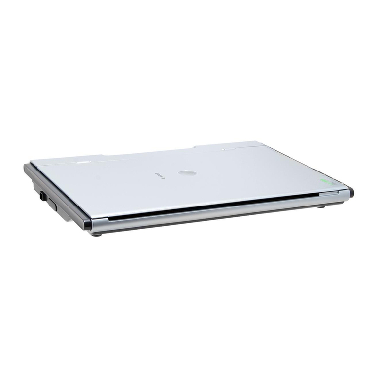
MEL M2D User manual

LASER-Scanner
for profile measurement
M2D
M2D
Intelligent Sensors
& Measuring Systems
Controlling
Monitoring
Measuring
MEL
MIKROELEKTRONIK GMBH


MIKROELEKTRONIK GmbH · Tel. +49 89 / 327150-0 · F x +49 89 / 319 20 23 · www.MELsensor.de
In 1985 the MEL GmbH was
founded with the purpose of
development and manufacturing of
sensors
First pilot projects were optical pre-
crash-sensors for cars, optical 2D-
scanners for security systems
The optical triangulation distance
sensors became a standard
product, as well as in 1994 the
scanner for 2D- and 3D-measure-
ments
The MEL GmbH is still a
development company for
customer specific solutions and is
well known for its high-tech
products throughout the auto-
motive industry
2D-Laser scanners are used for
quality assurance of mechanical
parts or for gap finding or seam
control with welding robots
The MEL Radio controlled
systems are used for the fast
identification of malfunctions and
the management of maintenance
and repairs in complex production
lines
The MEL Ident systems control
automatic paint shop systems in
order to enable a 100% opera-
tional readiness
First developments of measure-
ment- and control-systems starting
in 1969 First projects were
computerized controls for electron
beam welding machines, peri-
pheral components for machine
attached computers like opto-
couplers, AD-converters, high-
voltage-controllers, deflection units
or missile-controllers
In 1972 the first optical measure-
ment system for the detection of
the eye-movement was developed
This system was able to detect
rapid eye movements exactly The
contactless system could also
control X/Y-mirrors for the gene-
ration of stabilized pictures of the
retina With a resolution in the µm
range and the capture of move-
ments of up to 250 Hz this was
quite a sophisticated technology
Beginning in 1975, electronic was
developed for stratospheric
reseach missiles Many missiles
have been operated with the
directional control UNISTAB which
had been developed by Mr
Langer
35 Years of Experience in Test & Measurement
-3-
Table of contents page
Applications 2
Overview LASER Scanner 4
General description 6
LASER Scanner M2D 9
LASER Scanner M2DW 13
Evaluation Electronic:
i-Control 15
Blue Box 17
ISA Card 18
LASER Scanner M2-iLAN 19
LASER Scanner M2W-iLAN 25
Other products 27
Distributors 28

Functional Description
The Scanner M2D provides the
2-dimensional measuring of pro
file heights The measured ob
jects may consist of various ma
terials A laser line is projected
onto the target and the distance
to several points of the object is
measured by triangulation The
height (Z-axis) by distance (X-
axis) is measured The result is
the 2 dimensional contour of the
object
Typical applications
· Precise guidance of handling-
robots
-assembly of window panes
-positioning of car bodies
-gap adjustment in automotive
-welding seam tracking
-quality assurance
· Measurement for automatic as
sembly
-notch
-gap
-egde
-width and depth of fissures
-3D shapes and profiles
-fissured profiles
· Object detection
-discrimination, sorting
-go/no-go recognition
-completeness
-collision detection
-mobile gap measurement
· Welding
-seam control
-automatic welding robot
guidance
Method of measurement
The Line scanner M2D is working
according to the triangulation
method
The laser line is produced by a
pulsed laser diode and line
generating optics The diffuse
reflected light from the target is
projected onto a 2-dimensional
CCDArray (figure 1)
The different contour height of
the measured object produces
deviation of the reflected laser
line This deviation is corrected
and linearized trigonometrically
In addition to the distance infor-
mation (Z-axis), the position of
the measured point (X-axis) at
the laser line of the line scanner
is shown
Scanner construction
The scanner features a very com
pact construction since all the li
nearization and distance
measurements are already
handled completely from integra
ted hardware in the scanner it
self
A narrow-band filter protects the
sensor against external light influ
ence up to 5000 Lux The optics
are protected by an optionally
available, replaceable plastic
window These plastic windows
will repell welding plasma
sparks In case of wear the pro
tection window can be chan
ged quickly There are no mo
ving parts in the scanner, which
makes it completely free of
maintenance
Data output
There are several data-processing
unit of the M2 Series:
· ISA-PC board
· MEL Blue Box V2 for Ethernet-
Interface
· i-Control with integrated PC-104
-RS-232, CAN-Bus, Profibus-DP,
Ethernet
-EPP-parallel-Port, 4 Analog-
output 0-10V
-digital-output, digital-input
A comprehensive description of the
i-Controls can be found in the i-
control-manual
For more sophisticated applica
tions, industrial type PCs can be
ordered.
Measuring method
The object is scanned by the
fanshaped light beam of the laser
For each light beam, the points on
the object are calculated from
the scanner The coordinates of
these points are linearized and
then transferred as 2 by 2 values
The real profile of the surface
can be achieved as a repre
sentation of Z(X) The distances
of the measurement-points on the
X-axis are not constant and increa
se with the distance to the sensor
Errors may occur due to:
· direct reflection of the Laser
-6-
Fig 3
Begin scanrange X
End Scanrange X
Measuring range Z
Scanrange
Scanrange X
Measuring range Z
Scanrange
limited
Scanrange:
Standard
Scanrange:
4095 +10V
0V
0
4095
+10V
0
0V
4095 +10V
0V
0
4095 0
View:
(+10V)
(0V)
4095
0
+10V 0V
/
/
Fig 1
Z
X
Profile
Start
Scanrange
Scanrange
(Z-axis)
Object
Laserline
Scanrange
(X-axis)
MIKROELEKTRONIK GmbH · Tel. +49 89 / 327150-0 · F x +49 89 / 319 20 23 · www.MELsensor.de
Fig 2
Separate unit, depending on type of scanner
CCD-
Camera-
Chip
Laser
Linearization unit
Compensates:
- Optical distortion
- Scattered light effects
- pixel noise
- speccles
Remote scanner control
- Shutter speed
- External trigger
Real time
Image processing
Buffer
SCANNER
Control
Data output to PC for
further processing
Interfaces (dep on type):
- ISA-card
- Ethernet
- i-Control
Function principle
Linear optic
Scan range
Objective

beam from mirroring surfaces
with scratches
· multiple reflections at edges
· dark coloured objects, which
do not reflect enough light
· extreme variation of the sur
face finish
· no object within the measu
ring range
· interrupted laser beam and
shadows
· partly transparent surfaces (si
milar to glass or synthetic ma
terial
· for each measurement point the
corresponding intensity has to be
evaluated in addition to the dis
tance information {X;Z} in order to
obtain valid measurements
Application Notes
Measurement setup
· The resolution degrades with
increasing distance between
object and scanner, especially
with large scan ranges
· Best results are achieved when
the scanner beam is focused
rectangular to the objects sur
face Measurements with angu
lar deviation of up to 60° are pos
sible
· In order to avoid radio interfe
rence or noise, the scanner
should be electrically isolated
from the mounting surface
· Scanners with detached sensor
head are perfectly matched to
their individual electronic box
and should not be interchan
ged or mixed up
· The interface wire should not
be exchanged by a longer or
shorter one
Scanner Configuration
Adjustment of shutter speed
The shutter speed is regulated
depending on the brightness of
the reflected signal The diffuse
reflection of the objects surface is
influencing the shutter speed Sur
faces with more diffuse reflections
will yield brighter profiles, thus cau
sing shorter shutter times Darker
surfaces result in longer shutter ti
mes accordingly
Due to an automatic Gain Control
of the Video signal, the shutter
speed can be reduced, hence cau
sing of some extra noise
Depending on the reflections of the
surface, shutter speeds between
1/47,000 sec and 1/225 sec are
typical
With the supplied configuration
software, shutter speed and video
gain control can be adjusted (see
software description)
External Synchronisation
In order to synchronize the measu
rement exactly with a running pro
cess, it is possible to trigger the
scanner externaly The maximum
scan rate is 100 halfscans/sec
The measurement object is scan
ned 100 times / sec If the object is
not moving or moving very slowly,
then 2 consecutive measurements
can be integrated to one measure
ment, which will result in 2-times
the resolution in X-direction (fig 5)
Security advices
When setting up the Scanner it is
important that the Caution sign will
be visible very well
The power of the Laserbeam is so
low, that damage to the human eye
ist prevented by the wink reflex of
the eyelid It is harmless to view in
to the diffuse reflected laser line
nterfaces
Digital Outputs:
The scanner can output the digital
profile-data via the integrated
Ethernet-Interface Detailled infor
mation about interfaces and soft
ware-control can be found in the
respective hardware- and softwa
re manuals
Signal nputs:
The following functions can be ad
justed via Ethernet -Interface:
· Time of exposure
· Video-Gain
· Trigger-input
· Trigger with rising edge
A single measurement ca be trig
gered with the trigger input During
measurements no new triggers will
be accepted
Synchronization of two
Scanners
Option 1: alternating mode
Option 2: sync mode
Sync inaccuracy +/-15 µsec
Master slave mode can be defined
via jumpers onthe ISA-board, via
external wires with the Blue Box
The desired option can be selected
-7-
Fig 4
Z
Z
Z
X
X
X
1st half frame
2nd half frame
full frame
Fig 5
X
Z
I
X
Sensor
Measured object
Scan data Z(X)
Intensity I(X)
Area to suppress
Option 1 Option 2
Fig 7
MIKROELEKTRONIK GmbH · Tel. +49 89 / 327150-0 · F x +49 89 / 319 20 23 · www.MELsensor.de
Fig 6
CAUTION
LASER RADIATION
DO NOT STARE INTO BEAM
CLASS II LASER PRODUCT

in the respective program
There is no trigger mode possible
in the sync master slave mode
Data Link
· with i-Control:
Remote control of running software
applications, display of results and
status signals is possible via the
serial RS 232 interface:
Conversion of the analog signals
into digital signals:
· with the Blue Box V2:
The ethernet cable is connected
either through an adapter or th
rough a fixed wire Data from mul
tiple scanners can be grouped th
rough a commercial switch and
forwarded to a PC
Software
Following modules are supplied
with the M2D LASER-Scanner
standard software package:
· Windows software to read data
and to control the sensor :
· DLLs for Win 95/98/2000/NT/XP
DLL functions:
-read data routines
-sensor configuration
-filtering of measurement data
-visualization
-routines for cotinuous mode
Several sources are availble to
support development They are
available for the following environ
ments:
-DOS
-Turbo-Pascal
-Delphi
-Borland or Microsoft C++
-LabView
-Kylix / Linux
Special Software-Tools:
-DLL-Test-Software
-Configuration-Tool
ScanRecorder (Diagnose-Tool)
Demo-Software:
-M2D-Show
-M2D-Vision
Documentation for each of these
tools is available on request
Customized programs on re
quest.
M2D-W-Scanner
cooled by air/water
The M2D-W scanners with con
nectors for air/water cooling have
been developed für usage in hot
environments (up to 500°C) for ex
ample with welding robots and ex
truding machines
The protection window can be re
placed after removal of the heat
protection
Applications:
-Welding
-Welding seam control
-Rolling-mills
-Marine
Warranty
The warranty period is 24 months
Warranty voids with unauthorized
repairs or alterations, improper
usage In case of a malfuction ple
ase send the unit properly packed
to :
MEL Mikroelektronik GmbH
Breslauer Str 2
85386 Eching / Germany
or call us or send a fax :
Tel : +49 89 327 150 0
Fax: +49 89 319 20 23
Internet: www MELsensor de
E-Mail: info@MELsensor de
MEL is not liable for any damages
resulting the usage of its products
This data may be changed without
notice
-8-
Fig 14 Welding Robot Laser-Bug
weld
point
Protective
plate
Scanner
Heat shield
Fig 13
MIKROELEKTRONIK GmbH · Tel. +49 89 / 327150-0 · F x +49 89 / 319 20 23 · www.MELsensor.de

MIKROELEKTRONIK GmbH · Tel. +49 89 / 327150-0 · F x +49 89 / 319 20 23 · www.MELsensor.de
Other MEL products:
LASER Distance Sensors
Check of dimensions
Detection of position
Detection of material overlap
Control of presence and absence
Check of liquid level
Measuring of concentricity
Vibration analysis
Thickness measurement
Radio Remote Control STK and STK
Wireless control of all functional actuating elements to the PLC
Reduction of down time
When starting up or in case of breakdown the switching functions are
sent by radio from a small portable transmitter to the PLC
nductive Proximity Switch M
For the use in annealing ovens, painting plants etc
Inured to permanent temperatures up to 350 °C
Code Reader ES
Identification of product carriers in conveying systems
High temperature resistance (up to 400 °C)
Usuable in heavily soiled areas
-26-

MIKROELEKTRONIK GmbH · Tel. +49 89 / 327150-0 · F x +49 89 / 319 20 23 · www.MELsensor.de
error and technical modification reserved
MEL M KROELEKTRON K GmbH
Breslauer Str 2
D-85386 Eching
Tel +49 89 / 327150-0
Fax +49 89 / 319 20 23
info@MELsensor de
www MELsensor de
Motorway A9, exit Eching, direction "Ortsmitte",
- first street turn right into Paul-Käsmaier-Straße,
- turn left into Fürholzener Straße,
- turn left into Breslauer Straße,
last building on the left
Eching
München
E 45
9
E 53
92
99
E 52
92
94
8
8
E 52
E 45
E 553
95
E 54
96
995
68
69 Neufahrn
Freising
20 km0 5 10 15
N
Stuttgart 240 km
Berlin
565 km
Deggendorf
Salzburg/Österreich
Austria 165 km
Lindau 220 km
Schweiz
Switzerland
Garmisch-
Patenkirchen
Nürnberg
166 km Passau
Passau
How to find us:
Distribution partners in Europe ... and world wide:
Austria
Intermadox GmbH
Belgium
Multiprox NV
Denmark
EIE Proces
England
Sensors UK
Finland
Murrelektronik OY
France
Bullier Automation
Hungary
Sargent
taly
Leane International,
Roder, Sensormatic,
Sensortech, Tecnosens
Netherlands
AE Sensors BV
Norway
Primatech
Sweden
AB Liros
Switzerland
Bachofen AG
Spain
Sensing
Australia
Applied Measurement
Canada
A-Tech
China
Suzhou SV Technology Co , LTD
Japan
Sankyo International Corp
Korea
Micro Tech
Malaysia
Info Trax
Russia, Ukraine
ASMess
South Africa
ASS Tech
USA
Centella, Frontline Management,
H G Associates, Jack Colgan,
Precision Measurement,
Stress Analysis Services

Laser Measurement System Manual
M
Me
ea
as
su
ur
re
em
me
en
nt
t
S
Sy
ys
st
te
em
m
f
fo
or
r
C
Co
on
nc
cr
re
et
te
e
e
el
le
em
me
en
nt
ts
s
w
wi
it
th
h
M
M2
2D
D-
-L
La
as
se
er
r-
-S
Sc
ca
an
nn
ne
er
r
S
SV
VC
C
U
Us
se
er
r
M
Ma
an
nu
ua
al
l
V
Ve
er
rs
si
io
on
n
1
1.
.8
8.
.2
2
Editor: Reinhard Kutzner
Software: Denis Vaksic
MEL Mikroelektronik GmbH
Breslauer Str. 2
85386 Eching / Germany
Tel. +49 89 / 327 150-0
Fax +49 89 / 319 20 23
www.MELsensor.de April 2009
MIKROELEKTRONIK GmbH · Tel. +49 89/ 327 150-0 · Fax +49 89/ 319 20 23 · www.MELsensor.de
HB-ConcreteGrinding-SVC-E.doc page 1 of 43

Laser Measurement System Manual
Contents
User
Manual.........................................................................................................................................................................1User Manual
Contents...............................................................................................................................................................................2
System description........................................................................................................................................................... 3
Mounting of the Laser-Scanners ......................................................................................................................................3
Mounting of the electronic unit .........................................................................................................................................3
System components.........................................................................................................................................................5
Mechanical structure of the System .................................................................................................................................5
Protecting enclosure ........................................................................................................................................................5
Mounting the Laser-Scanners in relation to the mechanical probes................................................................................. 6
Adjustment procedure of Laser Scanner heads...............................................................................................................7
Angle adjustment .............................................................................................................................................................7
Height adjustment Z......................................................................................................................................................... 7
Laser line adjustment, X Offset........................................................................................................................................7
Machine Axis Adjustment Y, Z (X).................................................................................................................................... 8
Test fixture ....................................................................................................................................................................... 8
Electrical structure of the System...................................................................................................................................11
Description of system function ....................................................................................................................................... 11
Description of measurement cycle and data evaluation.................................................................................................11
Storage and screen display of measurement values...................................................................................................... 12
Determination of Y and Z-Offset-Values of the Laser-Scanners ....................................................................................12
Determination of the precise measurement position of the X-Axis................................................................................. 12
Definition of profile points 1............................................................................................................................................14
Definition of profile points 2............................................................................................................................................15
Software Configuration-Tool...........................................................................................................................................16
Application Software ...................................................................................................................................................... 17
Screen display in adjust mode ....................................................................................................................................... 17
Shutter control................................................................................................................................................................17
Scanner Parameter Adjustment .....................................................................................................................................17
Automatic Laser Intensity Control ..................................................................................................................................18
Adjust mode at the bridge ..............................................................................................................................................18
Cables and pipes ...........................................................................................................................................................20
Cable connection to digital inputs Start Stop.................................................................................................................. 20
Control signal for protection flap.....................................................................................................................................20
i-Control connections .....................................................................................................................................................21
24 V-DC supply and interface connector „Power“ .......................................................................................................... 21
Profibus- interface..........................................................................................................................................................22
Maintenance of the Laser-Scanners .............................................................................................................................. 23
Checking Laser-Scanner-Function.................................................................................................................................23
Maintenance and servicing the Laser-Scanners ............................................................................................................23
Cleaning the protective windows of the Laser-Scanners................................................................................................ 23
Adjustment of air pressure for the front flap opening...................................................................................................... 23
Open and close the flap manually..................................................................................................................................24
Eye safety and Laser-Protection class information ........................................................................................................ 24
How to behave...............................................................................................................................................................24
Calibration with compare to PL0-file...............................................................................................................................25
File system.....................................................................................................................................................................26
Example for Profibus test sequence...............................................................................................................................28
Typical result file (Log File) ............................................................................................................................................30
Program sequence.........................................................................................................................................................41
Measurement Sequence................................................................................................................................................43
Version information
Software version 1.8.2
22.September 2008
MIKROELEKTRONIK GmbH · Tel. +49 89/ 327 150-0 · Fax +49 89/ 319 20 23 · www.MELsensor.de
HB-ConcreteGrinding-SVC-E.doc page 2 of 43

Laser Measurement System Manual
S
Sy
ys
st
te
em
m
d
de
es
sc
cr
ri
ip
pt
ti
io
on
n
M
Mo
ou
un
nt
ti
in
ng
g
o
of
f
t
th
he
e
L
La
as
se
er
r-
-S
Sc
ca
an
nn
ne
er
rs
s
In the existing grinding machine of Max Bögl company, two Laser-Scanners of M2D-200/68 have been inte-
grated. For protection against water and dust, the Scanners are packed into a protection case with a pneu-
matic flap. The Laser-Scanners are mounted at the vertical arms fort he mechanic probes.
M
Mo
ou
un
nt
ti
in
ng
g
o
of
f
t
th
he
e
e
el
le
ec
ct
tr
ro
on
ni
ic
c
u
un
ni
it
t
On the bridge, close to the numerical and PLC control system, the MEL-i-Control is mounted. The extended
Scanner-cables and control cables for the pneumatic flaps are connected through the energy chains of the
motor units with the i-Control. The photos below show the mounting at the bridge.
MIKROELEKTRONIK GmbH · Tel. +49 89/ 327 150-0 · Fax +49 89/ 319 20 23 · www.MELsensor.de
HB-ConcreteGrinding-SVC-E.doc page 3 of 43

Laser Measurement System Manual
Mounting of i-Control
Picture of the machine
Profibus-connection
Scanner-connection
Ethernet-connection
Power supply
24 V
Mounting of i-Control
The i-Control is mounted directly at the rear metallic wall of the cabinet. This way of mounting makes sure,
that the iControl can dissipate the heat directly to the metallic wall. When the i-Control is mounted differently,
make sure that it is mounted on a metallic surface for good cooling.
MIKROELEKTRONIK GmbH · Tel. +49 89/ 327 150-0 · Fax +49 89/ 319 20 23 · www.MELsensor.de
HB-ConcreteGrinding-SVC-E.doc page 4 of 43

Laser Measurement System Manual
S
Sy
ys
st
te
em
m
c
co
om
mp
po
on
ne
en
nt
ts
s
The Laser-Measurement System consists of the following components:
oMEL-i-Control Sensor-Controller and Data Processing Unit
o2 Laser-Scanner in protection case with pneumatic flap
oScanner-connection cables
oMeasurement-Software, VNC-Server for remote access
oWindows-98SE Operating System
oPower Supply 24 V; 1.5A DC
M
Me
ec
ch
ha
an
ni
ic
ca
al
l
s
st
tr
ru
uc
ct
tu
ur
re
e
o
of
f
t
th
he
e
S
Sy
ys
st
te
em
m
The Laser-Scanners are mounted into a protection case with pneumatic flaps at the right and left vertical
arms of the mechanical probes.
The mounting position (height) of the Laser-Scanners has been selected so, that the position of the mechani-
cal probes is visible in the upper half of the of the Laser-Scanners vision range. With other words: the position
of the mechanical probes can be measured with the Laser-Scanners without changing the height of the verti-
cal arms. The Laser-Scanners must be moved of course sideways.
For calibration, a control measurement for both scanners is made, registering offset in the x- and y-axis to the
probes. The offset remains constant, when the position of the probes and the scanners is not changed. The
offset value is different for both scanners. The mounting position of the scanners does not allow, that the both
axis can move without the possibility of a collision. The software end switches, which limit the axis movement
sideways, must be set accordingly to prevent collision, when the scanners are in working position and protec-
tion flap open.
P
Pr
ro
ot
te
ec
ct
ti
in
ng
g
e
en
nc
cl
lo
os
su
ur
re
e
The two Laser-Scanners are mounted in protecting cases with a pneumatic flap. Inside of the protecting case
are a magnetic valve and a pneumatic cylinder. The machine supplies compressed air with 6 atmospheres.
The flap is opened with command 24 V from the PLC to the magnetic valve. When the flap opens, an air
stream is created from the plate with holes underneath the scanners front. The air forms a pressure cushion
under the scanner, rejecting dust and water
sparkles from the scanners front.
Picture at the right side: view on scanners front with
flap open.
The front plate has two windows, allowing the laser
projector sending the laser profile line to the
measured surface, and the camera window. The
pressure control screws allow adjusting the amount
of air streaming through the front plate.
Adjustment has been made for 4 atmospheres. This is considered the minimum pressure for opening and
closing the flap safely. During the final adjustments, the pressure may be raised to 6 atmospheres if needed.
In order to minimize the danger of collision with parts of the mechanical drive systems, the filter and pressure
regulators should be mounted on top of the Laser-Scanners protection cases.
MIKROELEKTRONIK GmbH · Tel. +49 89/ 327 150-0 · Fax +49 89/ 319 20 23 · www.MELsensor.de
HB-ConcreteGrinding-SVC-E.doc page 5 of 43

Laser Measurement System Manual
The Scanner connection cables are
mounted firmly at the Scanner head.
In the power chain of the machine
and in the vertical axis, the Scanner
cables are moved frequently.
Therefore the cable is in segments: 2
8 m segments in the power chain and
a 4 m extension cable have been
mounted at the end of the power
chain on the vertical axis.
The Scanner head connection cable
is mounted above the protection case
at the vertical arms.
Command cable for
pneumatic flap
Motor
Scanner cables Pressure control and filter
M
Mo
ou
un
nt
ti
in
ng
g
t
th
he
e
L
La
as
se
er
r-
-S
Sc
ca
an
nn
ne
er
rs
s
i
in
n
r
re
el
la
at
ti
io
on
n
t
to
o
t
th
he
e
m
me
ec
ch
ha
an
ni
ic
ca
al
l
p
pr
ro
ob
be
es
s
The Laser-Scanners have been mounted as close as possible to the mechanical probes. In order to allow the
use of both measurement systems independently from each other or in combination, the scanners have been
mounted so, that the position of the probe is in the vision range of the scanners. The protection flap can be
opened, without affecting the measurement capability of the mechanical probes.
For a comparative measurement, only the difference in position of the probes must be considered.
The difference in position from centre of axis of the Laser-Scanner to the mounting plate is 36.7 mm. This
must be added to the distance of the mechanical probe to the edge of the vertical arms. The better way is to
measure the distance with the procedure given further below.
A reference measurement needs to be performed
in order to determine the offsets in x, y and z.
When this measurement with the tactile probes
(Renishaw) has bee done, the offset values are
stored in the NC.ini file.
Before doing this, the Laser Scanner heads shall
be adjusted mechanically using the following
procedure:
The two Scanner heads are mounted differently
inside of the protection housings:
Scanner 1 is mounted in normal position. Scanner
2 is mounted at the side of the printed cover.
This way of mounting makes sure, that the laser
lines come out at the same position.
The protecting enclosure has 8 mounting holes
with thread M6. The additional mounting holes
allow shifting one of the two scanners to match
the position of the laser lines exactly. See also
following page!
The following chapter describes the adjustment
procedure required to define the offset values
between scanner measurement and machine
position / tactile measurement.
MIKROELEKTRONIK GmbH · Tel. +49 89/ 327 150-0 · Fax +49 89/ 319 20 23 · www.MELsensor.de
HB-ConcreteGrinding-SVC-E.doc page 6 of 43

Laser Measurement System Manual
A
Ad
dj
ju
us
st
tm
me
en
nt
t
p
pr
ro
oc
ce
ed
du
ur
re
e
o
of
f
L
La
as
se
er
r
S
Sc
ca
an
nn
ne
er
r
h
he
ea
ad
ds
s
A
An
ng
gl
le
e
a
ad
dj
ju
us
st
tm
me
en
nt
t
Step1: position the motor axes of left and right side at the same x position.
Mount Scanner 1 unit with protecting enclosure
Mount Scanner 2 unit with protecting enclosure
Open the protecting flaps
Provide a flat panel under the Laser Scanners so that the laser lines will be
visible when the lasers are switched on.
Check the mechanical adjustment of the protecting enclosure with a balance
as shown in the small picture at the right side.
This is the adjustment of the Scanner mounting angle rotation at
the y-Axis. The protection enclosure should be adjusted at 0°.
Connect Laser Scanner to i-Control
Power up 24V.
When the start.exe software launches automatically, wait until the
software application has loaded and exit the main application. For
a moment, we will start other software tools to support mechanical
adjustment procedure.
Step 2: launch “adjust.exe” from the directory C:\Program
Files\MEL. Adjust.exe is a software tool for Angle measurement.
When you launch the software tool, the lasers will be on and create
a visible red line on the underground. Activate the checkbox Show
Values at the lower right side of the screen (screenshot at the right
side). The “Show Values” function displays the grey angle display
in the two scanner windows. Additionally temperature and other
scanner values are displayed in this software tool. The main
benefit is the precise angle measurement. For best precision, the
underground must be flat and aligned horizontally. Use the same
principle to adjust the underground for this alignment step as for
alignment of the protecting enclosure (see step 1).
Now the Scanner mounting angle of rotation of x-axis should
be checked and adjusted. Best adjustment for both scanners is 0°.
H
He
ei
ig
gh
ht
t
a
ad
dj
ju
us
st
tm
me
en
nt
t
Z
Z
The adjust.exe tool also reads the height Z of both scanners.
Check, that both scanners are mounted in the same height, and
check the reading of the Numerical control PC for the axis position
in Z when the Scanner readings are brought to the same height
position.
L
La
as
se
er
r
l
li
in
ne
e
a
ad
dj
ju
us
st
tm
me
en
nt
t,
,
X
X
O
Of
ff
fs
se
et
t
Now the mechanical adjustment of the laser lines can be made, so
that the two projected laser lines of Scanner 1 and Scanner 2 are
exactly in the same line.
Check which scanner must be probably shifted to the other screw
holes to make the position of laser lines exactly the same. The
laser lines must not be rotated; they shall form a unique straight
line. If necessary change position of one of the axis.
When this is ok, note the machine axis encoder values.
When done, exit the software tool adjust.exe.
MIKROELEKTRONIK GmbH · Tel. +49 89/ 327 150-0 · Fax +49 89/ 319 20 23 · www.MELsensor.de
HB-ConcreteGrinding-SVC-E.doc page 7 of 43

Laser Measurement System Manual
MIKROELEKTRONIK GmbH · Tel. +49 89/ 327 150-0 · Fax +49 89/ 319 20 23 · www.MELsensor.de
M
Ma
ac
ch
hi
in
ne
e
A
Ax
xi
is
s
A
Ad
dj
ju
us
st
tm
me
en
nt
t
Y
Y,
,
Z
Z
(
(X
X)
)
launch the “Ausrichten.exe” software tool.
When the software “Ausrichten.exe” is active, the laser light will be
shining.
Have the concrete panel or a test fixture under the lasers, so that
the software will show a profile.
Check the position of scanner 1 and adjust mechanical position of
the test fixture or machine axis so, that scanner 1 has an ideal
profile.
The test fixture should be positioned in a way that later scanner 2
can reach the same position as scanner 1. Also the test fixture
should be positioned horizontally and stable, so that it will not
move by hazard.
On the test fixture, make a marking where the laser beam of
scanner 1 hits the target. Note the machine axis position precisely.
Remove scanner 1 from the test area, so that scanner 2 can go
there without collision.
Now change machine position for scanner 2, so that scanner 2 will
see the same object at the same (previously marked) position as
scanner 1 before.
The software tool needs to be left unchanged to give a clear
indication of machine position.
Note the precise position of scanner 2 over the test fixture.
Now the Numerical control PC can calculate the offsets in Y and Z
between scanners and machine axis encoders gathered in the steps before.
When “Ausrichten” is finished, exit the software.
T
Te
es
st
t
f
fi
ix
xt
tu
ur
re
e
The adjustment of the axis is best done with a test fixture
providing a sharp edge. This allows better identification the
position of the axis as a shallow edge. The test fixture also
should have a defined height. This allows a quick visual
control of the scanners viewing range.
Picture at the right side: Drawing of test fixture
The angle should be 110°, this will allow to check the
mounting position of the scanner and the scanners angle
measurement ability. The other dimensions could be
changed. The total height should be not higher than the
scanners viewing range. In best case the height is 70 … 100
mm.
The surface of the test fixture should be flat and painted with
light grey colour, like the car paint spray colour (primer)
available in pit stops. This surface will give good profile
reading with the laser scanners.
HB-ConcreteGrinding-SVC-E.doc page 8 of 43

Laser Measurement System Manual
MIKROELEKTRONIK GmbH · Tel. +49 89/ 327 150-0 · Fax +49 89/ 319 20 23 · www.MELsensor.de
Drawing of protection case, position of Laser beam out position and vision range of Laser-Scanner left side
HB-ConcreteGrinding-SVC-E.doc page 9 of 43

Laser Measurement System Manual
MIKROELEKTRONIK GmbH · Tel. +49 89/ 327 150-0 · Fax +49 89/ 319 20 23 · www.MELsensor.de
Drawing of protection case, position of Laser beam out position and vision range of Laser-Scanner right side
HB-ConcreteGrinding-SVC-E.doc page 10 of 43

Laser Measurement System Manual
MIKROELEKTRONIK GmbH · Tel. +49 89/ 327 150-0 · Fax +49 89/ 319 20 23 · www.MELsensor.de
E
El
le
ec
ct
tr
ri
ic
ca
al
l
s
st
tr
ru
uc
ct
tu
ur
re
e
o
of
f
t
th
he
e
S
Sy
ys
st
te
em
m
The two Laser-Scanners are connected with a special cable to the i-Control unit. The interface to the PLC is a
Profibus connection; the i-Control unit is a Profibus slave and the Profibus address is firmly set to 5. The nu-
merical control system receives data with a file transfer over the Ethernet network.
Picture above: schematic signal path
D
De
es
sc
cr
ri
ip
pt
ti
io
on
n
o
of
f
s
sy
ys
st
te
em
m
f
fu
un
nc
ct
ti
io
on
n
The numerical control system creates a measurement routine for the concrete elements. The Laser-
measurement system receives from the PLC system the information on concrete element number (plate
number), number of hooks, the coordinates of the measurement window A, measurement window for the
Dübel, and measurement window B.
The numerical control system has no Profibus connection, therefore the numerical control system (NC) sends
its data to the PLC system, and the PLC system sends it over the Profibus to the i-Control. This may be
changed in future machines, without changing the interface to iControl.
The plate number is equal the file name, which will be written to the result file on the internal drive of the i-
Control after finishing the measurement.
In order to minimize the amount of data to be transmitted, only an average value for the measurement win-
dow coordinates is transferred to the i-Contol. The i-Control receives from two fast digital outputs at the PLC
(start /stop) the signals for the two channels when to start and stop the measurement. The i-Control performs
the measurement and writes the results to the shared folder “Transfer” on the internal disk drive. At the end of
the measurement cycle, the i-Control sends a message “done” (“fertig”) to the PLC. The PLC then triggers the
NC to get (read) the file from the internal drive. In order to allow access, the folder is shared without password
requirement.
D
De
es
sc
cr
ri
ip
pt
ti
io
on
n
o
of
f
m
me
ea
as
su
ur
re
em
me
en
nt
t
c
cy
yc
cl
le
e
a
an
nd
d
d
da
at
ta
a
e
ev
va
al
lu
ua
at
ti
io
on
n
Each time when the start position of the measurement window is reached, the NC triggers the fast digital out-
puts of the PLC. The i-Control reacts upon this signal, and stores the profiles of the measurement window.
The profile points, calculated from this profile were written to file at the end of the measurement cycle. During
the phase of active measurement, they were held in RAM.
MEL sends on the Profibus busy, until the evaluation routine is active and data is written into a file in the
folder “Transfer”. When the file is saved, the signal “done” (fertig) is set active (see description of Profibus in-
terface on page 20)
HB-ConcreteGrinding-SVC-E.doc page 11 of 43

Laser Measurement System Manual
MIKROELEKTRONIK GmbH · Tel. +49 89/ 327 150-0 · Fax +49 89/ 319 20 23 · www.MELsensor.de
S
St
to
or
ra
ag
ge
e
a
an
nd
d
s
sc
cr
re
ee
en
n
d
di
is
sp
pl
la
ay
y
o
of
f
m
me
ea
as
su
ur
re
em
me
en
nt
t
v
va
al
lu
ue
es
s
After start signal, the next scann profile is captured. On screen, the progress from hook to hook can be seen,
without having false pictures displayed.
The checkbox “adjust” switches the permanent update function. When the checkbox is activated,
the screen is permanently updated. For normal operation, the adjust checkbox must be unchecked.
For remote access VNC software has been installed. The VNC Server should be used (activated) only for
service task, and been deactivated straight after finishing the service task. The VNC service takes up a lot of
system performance. When left active in background, measurement results could be faulty by doing so!
D
De
et
te
er
rm
mi
in
na
at
ti
io
on
n
o
of
f
Y
Y
a
an
nd
d
Z
Z-
-O
Of
ff
fs
se
et
t-
-V
Va
al
lu
ue
es
s
o
of
f
t
th
he
e
L
La
as
se
er
r-
-S
Sc
ca
an
nn
ne
er
rs
s
The mechanical mounting position of the Laser-Scanners has and offset in Y and Z relative to the tactile sen-
sors.
D
De
et
te
er
rm
mi
in
na
at
ti
io
on
n
o
of
f
t
th
he
e
p
pr
re
ec
ci
is
se
e
m
me
ea
as
su
ur
re
em
me
en
nt
t
p
po
os
si
it
ti
io
on
n
o
of
f
t
th
he
e
X
X-
-A
Ax
xi
is
s
The position of measurement in the direction of movement (= x axis) is defined by the NC.ini file. The start
signal is send over the fast digital outputs of the PLC to the digital inputs of i-Control. The i-Control finally
saves the profiles and evaluates the profile points according to definition on page 14
The delay between reaching the starting coordinate, the trigger impulse at the outputs of the PLC, the reac-
tion time of i-Control and the position, where the Laser-Scanners have made their measurement cannot be
calculated precisely. The delays depend on internal cycle times of the NC, the PLC and last not least the re-
action time of i-Control. Therefore a simple method for determination of the measurement location has been
designed.
On the last hook, a ramp with 10% slope is placed. The last profile
remains in the screen display. The height of the pictured ramp in
display can be evaluated, in order to know the position of the last
measurement.
HB-ConcreteGrinding-SVC-E.doc page 12 of 43
Table of contents
Other MEL Scanner manuals
