Melco Advantage 18 User manual

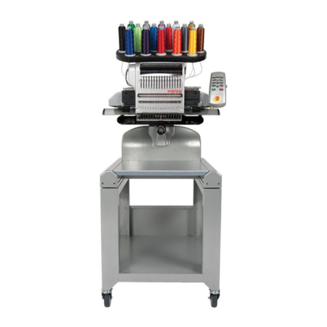
•18 Colors
•One Needle
•Automatic Color Change
•Automatic Rethreading
•Under Thread Control
A Saurer Group Company
Operation Manual for
the Advantage 18
embroidery peripheral
Part Number 110265-01, Revision A

1575 West 124th Avenue
Denver, Colorado 80234
United States of America
Copyright © Melco Embroidery Systems, 1995.
ALL RIGHTS RESERVED No part of this publication may be reproduced, stored in a retrieval system, or
transmitted in any form or by any means (electronic, mechanical, photocopying, recording, or
otherwise) without prior written approval of Melco Embroidery Systems. Melco reserves the right to
revise this publication and to make changes in it at any time without obligation of Melco to notify any
person or organization of such revisions or changes.
All precautions have been taken to avoid errors or misrepresentations of facts, equipment, or
products. However, Melco Embroidery Systems does not assume any liability to any party for loss or
damage caused by errors or omissions.
Printed in the United States of America
FIRST DRAFT: November 2, 1995

Table of Contents
1. Introduction and Installation
Physical Arrangement 1 - 1
The Controller 1 - 2
The Embroidery Head 1 - 2
The Thread Tree 1 - 2
The Keyboard 1 - 2
The Pantograph 1 - 2
Installation 1 - 3
Power Requirements 1 - 3
Static Electricity 1 - 3
Inspecting Your Embroidery Peripheral 1 - 3
Unpacking the Advantage 18 1 - 3
Tables And Cabinets 1 - 3
Embroidery Peripheral 1 - 3
The Air Compressor 1 - 6
Canned Compressed Air 1 - 6
Configuring The Advantage 18 1 - 6
What to Configure 1 - 6
The Peripheral Program 1 - 7
The Unit Number 1 - 7
The Language 1 - 7
How to Configure 1 - 7
Start-Up Messages 1 - 8
2. Operating the Advantage 18
How Threads Are Spliced 2 - 1
Threading the Advantage 18 2 - 1
Threading to the Selector Carriage 2 - 1
Inserting the Thread into the Splicing Cell 2 - 3
Rethreading After a Failure 2 - 3
Thread Types and Needles 2 - 5
Thread Types 2 - 5
Needles 2 - 5
Tensions 2 - 5
The Upper Tension 2 - 5
Bobbin Tension 2 - 5
Installing a Needle 2 - 6
Hooping 2 - 7
Hooping Flat Goods 2 - 7
Loading The Hoop 2 - 8
Cap Frames 2 - 9
Installing the Cap Frame Drive 2 - 9
Cap Hooping 2 - 11
Using a Raised Needle Plate 2 - 11
Advantage 18
i
Operation Manual

Keyboard Operation 2 - 12
Introduction 2 - 12
The Keys and Their Functions 2 - 12
Key Combinations 2 - 13
Sending a Design 2 - 14
Receiving a Design 2 - 14
3. The Setup Menus
An Overview of the Advantage 18 Menus 3 - 1
Design Menu 3 - 2
Selecting a Design 3 - 2
Deleting a Design 3 - 2
Color Menu 3 - 3
An Example 3 - 4
Change Now 3 - 4
Tension Menu 3 - 5
Select the Thread Position 3 - 6
Select the Tension Setting 3 - 6
Orientation Menu 3 - 6
Setting Orientation 3 - 6
Run Design Menu 3 - 7
The Idle Menus 3 - 7
4. The Customizing Menus
Frame Menu 4 - 1
The Frame Idle Display 4 - 2
Return To Origin 4 - 2
Trace Menu 4 - 3
Home Menu 4 - 4
Set Home 4 - 4
Hoop Limits 4 - 4
Power Fail Rescue 4 - 5
Move Menu 4 - 6
When to Use The Move Menu 4 - 6
Trim Menu 4 - 8
Setting the Options 4 - 8
Trim Immediate 4 - 8
Jump Count 4 - 8
Bobbin Menu 4 - 9
The Splicing Menu 4 - 9
Change Thread 4 - 10
Insert Thread 4 - 10
Valve 1 Off 4 - 11
Up Trim Mtr On 4 - 11
Trim Thread 4 - 12
Draw Motor 4 - 12
Low Pressure On 4 - 13
Table of Contents
Operation Manual
ii
Advantage 18

High Pressure On 4 - 13
Reset Menu 4 - 14
System Reset 4 - 14
Hard Reset 4 - 14
5. Operator Maintenance
Cleaning the Advantage 18 5 - 1
Cleaning Your Machine’s Exterior Surfaces 5 - 1
Cleaning the Rotary Hook Area 5 - 1
Lubricating the Advantage 18 5 - 2
Lubricating The Embroidery Head 5 - 2
Rotary Hook 5 - 2
Needle Bar 5 - 3
Needle Bar Driver 5 - 4
Upper Connecting Rod 5 - 4
Lower Connecting Rod 5 - 5
Lubricating The Beam 5 - 6
Lubricating the Pulley Assembly 5 - 7
Lubricating the X-Carriage Rollers 5 - 9
Lubricating the Y-Rails 5 - 10
Lubricating the Lower Trimmers 5 - 11
The Rear Trimmer Parts 5 - 12
The Front Trimmer Parts 5 - 12
Embroidery Head Timing 5 - 13
Machine Out Of Timing 5 - 13
Making A Stitch 5 - 14
Setting Timing 5 - 15
Needle Depth Check/Adjustment 5 - 15
Hook Timing 5 - 17
Checking Hook Timing 5 - 18
Adjusting Hook Timing 5 - 19
Cleaning the Color Change Area 5 - 21
Color Change Cover Removal 5 - 21
The Manifold 5 - 22
Upper Trimmers 5 - 23
Pretensioner 5 - 24
Addendums
A. Glossary of Embroidery Terms
B. Error Messages
C. Hoop Sizes
D. The Quick Reference Guide
INDEX
Table of Contents
Advantage 18
iii
Operation Manual

Table of Contents
Operation Manual
iv
Advantage 18

1. Introduction and Installation
The Advantage 18 is an 18 color embroidery peripheral using an innovative, air driven, color
change process that automatically rethreads its single needle. You may embroider a design with up
to 18 colors without pausing to change spools or manually rethread the needle. In addition to
embroidering on flat goods, the Advantage 18 embroiders on caps using the optional cap frame
attachment.
WARNING! For operator safety, Never allow untrained
personnel operate the Advantage 18.
Physical Arrangement
The Advantage 18 has five sections: the controller, the embroidery head, the thread tree, the
keyboard, and the pantograph (see Figure 1-1).
Thread Tree
Controller
Keyboard
Pantograph
Embroidery
Head
Figure 1-1
1 - 1
110265-01, Rev. A 1. Introduction and Installation

The Controller
The controller contains the printed circuit boards (PCB’s) and electronics that control much of the
machine’s operation.
The Embroidery Head
The embroidery head consists of the parts that move the needle, advance the thread, and produce
stitches.
The Thread Tree
The thread tree holds up to 18 spools of thread and mounts on the embroidery head. Its
connecting plastic tubes feed the individual threads from the spools to the thread select carriage.
The Keyboard
Commands are given to the peripheral through the keyboard. The Liquid Crystal Display (LCD)
displays informative messages. The main power supply and the motor that moves the pantograph
forward and backward are located under the keyboard cover.
The Pantograph
The pantograph (see Figure 1-2) moves the hoop right or left (the X axis) and forward or backward
(the Y axis). The beam is the arm of the pantograph that moves forward or backward. Inside the
beam is the X-carriage that moves left or right. The hooped garment attaches to the X-carriage. As
the X-carriage moves the hoop left or right, the beam moves the X-carriage forward or backward.
This movement controls the placement of the stitching.
Beam
X-Carriage
and Hoop
Attachment
Figure 1-2
1 - 2 Physical Arrangement
Advantage 18 Operation Manual Melco Embroidery Systems

Installation
This section explains how to get your Advantage 18 unpacked, powered up, and connected to your
computer. Directions for installing software are in the software operation manuals.
If you are using the Advantage 18’s optional disk drive, skip the directions for connecting the
Advantage 18 to a computer. All instructions for the optional disk drive are in its operation manual.
Power Requirements
Electricity can have power spikes or surges that may affect your computer or embroidery
peripheral’s operation. Melco suggests a dedicated power for your system with a line conditioner.
Inspecting Your Embroidery Peripheral
Inspect all cartons for physical damage. If any damage is found, contact the shipper.
Unpacking the Advantage 18
When cutting open the boxes be careful not to damage any of the equipment. Continue to inspect
the parts for any physical damage not apparent from the condition of the cartons. Again, contact
the shipper to report any damage.
Tables And Cabinets
Unpack and place the work station furniture before unpacking the embroidery equipment.
Embroidery Peripheral
1. Carefully cut and remove the binding straps from the cardboard shipping carton containing the
embroidery peripheral.
2. Lift the top cover off the outside
carton.
3. Remove the outside carton from
the bottom cover.
4. Remove any packing boxes and
protective pads from around the
embroidery head (see Figure 1-3).
CAUTION: Use two
people to remove and
place the embroidery
peripheral.
Foam Cushions
Packing Boxes
Embroidery
Head
Figure 1-3
Unpacking the Advantage 18 1 - 3
110265-01, Rev. A 1. Introduction and Installation

5. Grasp the underside of the machine at the four locations indicated in Figure 1-4.
6. Keep the embroidery peripheral level. The unit and foam packaging should come out of the
carton with relative ease.
7. Place the embroidery peripheral onto its dedicated work station.
8. Set the 115V/220V selector switch to the proper setting for your power supply. The switch is
just to the right of the ON/OFF switch (see Figure 1-5).
Machine
ON/OFF
Switch
Voltage
Selector
Switch
Attach Power
Cable here
Network
Cable
Terminator
Cable
Rear of Computer
Rear of Peripheral
Figure 1-4
Lift Here
Lift Here
Figure 1-5
1 - 4 Installation
Advantage 18 Operation Manual Melco Embroidery Systems

9. Attach the power cable to the rear of the unit as shown in Figure 1-5.
10. Still referring to Figure 1-5, install the network cable between the computer and the Advantage
18. If you only have one peripheral device attached to the computer, install the terminator
cable to the machine as the figure shows. If more than one peripheral device is attached to the
computer, install the terminator cable on the last peripheral in the series.
11. Install the power cords of the computer, the monitor, and the embroidery peripheral to the
power source.
The Air Compressor
You must provide an air compressor for attaching the Advantage 18. The air compressor must meet
the following requirements:
•Air pressure of 100 to 120 psi (pounds per square inch)
•Air flow of 2 scfm (standard cubic feet per minute) at 90 psi for each Advantage 18
•A regulator with a minimum range of 70 to 100 psi
•A 5 micron particle filter
•A 0.5 micron oil-coalescing filter
The Advantage 18 comes with a 6 foot long air supply line with a standard quick-disconnect fitting.
To install the tubing on the Advantage 18:
1. Route the free end of the tubing through the open base of the thread tree.
2. Insert the end of the tubing into the air supply fitting with a red ring around it. It is located just
in front of the thread tree, at the back of the color change assembly.
3. Push the tubing into the fitting as far as it will go.
Canned Compressed Air
Use a can of compressed air that is free from contaminants to insert threads through the thread
guide tubes.
Configuring The Advantage 18
When turning on the Advantage 18 for the first time it must be configured to operate properly.
After configuration is completed, each time the Advantage 18 is turned on it checks its memory for
the needed data. The peripheral requires reconfiguration when a new PCB is installed.
Canned Compressed Air 1 - 5
110265-01, Rev. A 1. Introduction and Installation

What to Configure
The three items of information set during configuration are:
•Peripheral Program
•Unit Number
•Language
The Peripheral Program
The CPU used in the Advantage 18 is also used in other Melco peripherals. The peripheral program
is set to match the CPU to the peripheral it is controlling. On new units the peripheral program is
set at the factory. However, if you replace the CPU board, you must reset the peripheral program. If
the Advantage 18 is configured with the incorrect peripheral program, it will not operate properly,
and may be damaged.
The Unit Number
A network address or unit number for each peripheral attached to an EDS system must also be set
at the peripheral. The number may be between 1 and 16 when using EDS II software or between 1
and 64 when using other Melco software. Each peripheral must have a unique unit number.
Before sending designs to the Advantage 18, enable the unit number on the computer. See your
software operation manual for instructions.
The Language
Set the language displayed by the LCD to either English or Spanish.
How to Configure
Access the configuration mode by
following these steps:
1. Before you turn on the Advantage 18,
locate the keyboard in the upper right
area of the peripheral as shown in
Figure 1-6.
2. Locate the power switch at the rear of
the unit. It is a rocker switch above
the power cord as shown in Figure
1-5.
3. Press and hold [ALT], [⇑], and [⇓] while
turning the power ON.
Keyboard
Figure 1-6
1 - 6 Configuring The Advantage 18
Advantage 18 Operation Manual Melco Embroidery Systems

4. Continue to press these keys until the unit ‘‘beeps’’ and the display shows a message that says
ADV-18 (or some other peripheral identification code). Release the three keys.
5. If the LCD displays anything other than ADV-18, press [⇑] or [⇓] until it displays: ADV-18.
6. Press [ENTER] to set the peripheral program.
7. Press [⇑] or [⇓] and the LCD will display: UNIT NUMBER 01. Keep pressing the arrow key until the
number you want displays. You cannot have two peripherals with the same unit number
attached to the same computer.
8. Press [ENTER] to set the unit number.
9. The last item you select is the display language. Press [⇑] or [⇓] to display English or Spanish and
press [ENTER] to select that language.
Start-Up Messages
Once configured, a series of messages will display during power up. Usually the messages are
simply informational, but sometimes they will require a keyboard entry from the operator. The
messages displayed will depend on the combination of the computer and peripheral operating
modes.
When there is a completed link to the computer the series of messages are:
DSKBIOS Version# Bytes of free memory
DNLOAD REQUESTED
POWER UP. . .
ADV-18 Version#
If a link to the computer is not make because it is not on or it is busy, the following messages will
flash alternately until the Advantage 18 can link:
DSKBIOS version # bytes of free memory
UNIT #
If the Advantage 18 finds a problem in its self-check, it will display the appropriate error message
and wait for a response.
Appendix B contains a complete listing of the error messages.
How to Configure 1 - 7
110265-01, Rev. A 1. Introduction and Installation

1 - 8 Start-Up Messages
Advantage 18 Operation Manual Melco Embroidery Systems

2. Operating the Advantage 18
How Threads Are Spliced
During a color change, both the current and new threads enter into the thread splicing cell. Inside
the splicing cell a short, forceful burst of air fluffs out the fibers of both threads causing them to
intertwine, making a secure slice between them. The old thread is then pulled through the needle,
followed by the splice and the new thread. The new thread is trimmed after passing through the
needle, and the old thread and splice are directed into a holding bin for later disposal. This
patented process allows the Advantage 18 to perform color changes and rethreading automatically
while using a single needle and tensioner.
Threading the Advantage 18
Although the Advantage 18 will automatically rethread when it performs a color change, you may
need to perform manual threading when the following occurs:
•Initial set-up
•Using short-fiber threads that do not splice well
•A thread break
•Mechanical failures
Follow these directions to thread the machine:
Threading to the Selector Carriage
1. Put a spool of thread on position number 1 of the thread tree.
2. Insert an inch or two of thread into the center of the thread guide tube.
3. Use a can of compressed air to direct a short burst of air into the tube as shown in Figure 2-1.
The compressed air will force the thread through the tubing to the thread selector carriage.
Thread Spool
Thread Guide Tube
Compressed Air
Figure 2-1
Threading to the Selector Carriage 2 - 1
110265-01, Rev. A 2. Operating the Advantage 18

4. Lift the pretensioner magnet. Position the thread in the groove, over the idler roller, and through
the guide hole as shown in Figures 2-2 and 2-3.
5. Repeat steps 1 through 4 for all the thread positions.
6. Replace the pretensioner.
7. Trim the ends of the thread to 1/8 inch in front of the carriage (see Figure 2-3).
Pretensioner Magnet
(lifted for thread placement)
Thread tubes
from the
thread tree
Idler Roller
Guide Hole
Groove
Figure 2-2
Pretensioner Magnet
(in operating position)
Threads trimmed
to 1/8 inch.
Figure 2-3
2 - 2 Threading the Advantage 18
Advantage 18 Operation Manual Melco Embroidery Systems

Inserting the Thread into the Splicing Cell
1. Move the selector carriage to the desired thread position by pressing [ALT][⇐] to move one
space to the left or [ALT][⇒] to move one space to the right.
2. Press [ALT][ENTER] to display one of three idle menus. Press [ENTER] to toggle through these
menus until reaching one that displays: THD: 1* TENSION: 27. The number with the asterisk
beside it is the current thread position of the selector carriage. A complete description of the
Idle menus is in the next chapter.
3. Press [ALT][⇑] to move the selector carriage to thread position 18 or press [ALT][⇓] to move the
selector carriage to thread position 1.
4. To move the selector carriage to the previously selected thread and insert it through the splicing
cell, press the [FAST/SLOW] key. The only time [FAST/SLOW] will perform this function is when
it is the first key pressed after moving the selector carriage with one of the [ALT][arrow key]
combinations.
NOTE: By allowing the selector carriage to move off the selected thread position and then travel
back to it before performing an insert, the tails of the neighboring threads become
positioned to avoid interference. Using [ALT][⇑] or [ALT][⇓] stores the previous thread
position so the selector carriage knows where to return. Press [FAST/SLOW] immediately
after accessing [ALT][⇐] or [ALT][⇒] to perform an insert at that position.
OR
Access the insert thread option in the Splicing Menu. This is discussed in the Splicing Menu section
later in this chapter.
5. Finish threading the machine using Figure 2-4 as a guide.
Rethreading After a Failure
If a thread fails to insert through the splicing cell, perform these recovery steps before trying the
insert again.
1. Press [ALT][⇑] or [ALT][⇓] to move the selector carriage all the way to the left or right depending
on which gives you the best access to the thread position.
2. If the tail of the thread is free, trim it back to 1/8 inch.
OR
If the tail of the thread has become tangled under the color change cover, be sure to clear the
entire thread path. You may have to remove the color change cover to do this.
3. Trim the thread to 1/8 inch.
4. Press [FAST/SLOW]. The selector carriage will move back to the previous thread and perform an
insert.
Rethreading After a Failure 2 - 3
110265-01, Rev. A 2. Operating the Advantage 18

The Advantage 18 Thread Path
NOTE: The thread is passed
between the disks of the
tensioner only once.
Figure 2-4
2 - 4 Threading the Advantage 18
Advantage 18 Operation Manual Melco Embroidery Systems

Thread Types and Needles
Thread Types
The Advantage 18 can perform automatic color changes between a variety of thread types.
However, the longer the thread fibers, the better the splice. Because synthetic threads have longer
fibers than natural threads such as cotton, a synthetic to synthetic splice is the most consistent. The
following table lists general guidelines for the splicing quality of different thread types. Of course,
the two threads in a splice can be different types of thread. Even if a thread does not splice well,
you may embroider with it on the Advantage 18 by threading it manually.
Synthetic Best for splicing
Blends of Synthetic and Natural Better than all natural
Natural May need manual rethreading
Monofilaments Must be manually threaded
Metalics Must be manually threaded
Needles
During an Advantage 18 color change, the actual splice of the two threads passes through the eye
of the needle. For the splice to easily pass through the eye, use a standard 80/12 size needle or
larger.
Tensions
Excellent embroidery quality is achieved when both the upper thread and bobbin thread tensions
are set properly. Experience and practice allows customized tension settings based on factors such
as: threads, material, backing, needle type, stitch size, and hooping.
The Upper Tension
There is one upper tensioner on the Advantage 18 used by all 18 thread positions. Because
different types and weights of threads require different tensions, the Advantage 18 tensioner is
designed to store the tension setting for each thread position in memory.
When a tension is reset, the new setting replaces the old one in memory for that thread position.
Keeping the same types and weights of threads in the same thread positions will reduce the
number of tension adjustments.
Bobbin Tension
The same factors affecting upper tensions affect bobbin tension. The bobbin tension is adjusted
manually, however, by rotating a set screw on the bobbin case (see Figure 2-5).
Bobbin Tension 2 - 5
110265-01, Rev. A 2. Operating the Advantage 18

1 Put the bobbin spool into the bobbin case as illustrated in Figure 2-5. When looking at the open
end of the bobbin case, the thread should rotate clockwise off the bobbin spool when you pull
on the thread.
2. Pass the thread through the slit in the bobbin case and under the spring.
3. Using a small, flat-blade screw driver, turn the set screw until you feel a slight resistance when
the thread is pulled from the bobbin. Set the tension so that when you hold the bobbin case
suspended by its thread:
•No thread feeds out when you are not moving it
•About an inch of thread feeds out when you jiggle it slightly
4. With the bobbin tension adjusted, pass the bobbin thread through the bobbin case pig tail.
Installing a Needle
The needle clamp set screw holds the needle in place
as shown in Figure 2-6. Using the small, flat-blade
screw driver from the operator’s tool kit:
1. Turn the set screw counterclockwise until the
needle can slide down and out of the needle bar.
2. With the scarf of the new needle toward the rear
of the embroidery head, slide the needle into the
needle bar as far as it will go and tighten the set
screw.
Side View End View
Bobbin Case
Pigtail
Bobbin
Spool
Note the direction that the thread is wound on the
bobbin spool for insertion into the bobbin case.
Bobbin Case
Spring
Set
Screw
Thread
Slit
Figure 2-5
Figure 2-6
2 - 6 Installing a Needle
Advantage 18 Operation Manual Melco Embroidery Systems
Table of contents
Other Melco PDA manuals
