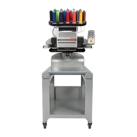
Melco EP 1B User manual

Technical Manual
for the EP 1B
embroidery machine
Part Number 12616, Revision B
•Single Head, Single Needle
•Easy To Operate
•Low Power Consumption
•High Quality Results

1575 West 124th Avenue
Denver, Colorado 80234
United States of America
Copyright © Melco Embroidery Systems, 1999
ALL RIGHTS RESERVED No part of this publication may be reproduced, stored in a retrieval system, or
transmitted in any form or by any means (electronic, mechanical, photocopying, recording, or otherwise)
without prior written approval of Melco Embroidery Systems. Melco reserves the right to revise this
publication and to make changes in it at any time without obligation of Melco to notify any person or
organization of such revisions or changes.
All precautions have been taken to avoid errors or misrepresentations of facts, equipment, or products.
However, Melco Embroidery Systems does not assume any liability to any party for loss or damage caused by
errors or omissions.
Printed in the United States of America
First Printing: April, 1999
Revision B June, 1999

EP 1B Technical Manual I 06/99
Table of Contents
1. Setting Method for Adjusting or Repairing Machine 1
2. Replacement of Hook Race (unit) 2
3. Replacement of Needle Bar (unit) 9
4. Removal of X-Y Cover 13
5. Replacement of A Board, LAN Board, Power Supply Unit 24V
and Power Supply Unit 5V 16
6. Replacement of K Board and Display Tube (VFD) 18
7. Replacement of Power Supply Switch, Inlet and
Connector Fixing Plate 20
8. Replacement of X-Y Mechanism 21
9. Removal of Machine 23
10. Replacement of Thread Breakage Sensor, S Board(unit),
Upper Shaft Sensor and Solenoid. 24
11. Mounting of Machine 29
12. Adjustment of Bobbin Thread Sensor, Solenoid and
Thread Breakage Sensor. 30
13. Replacement of Wire pulley 33
14. Replacement of X-Y Carriage 35
15. Replacement of Y(X) Stepping Motor and Y(X) Sensor 39
16. Replacement of Gear 42
17. Self-diagnosis Mode 49

Table of Contents
12616, Rev. B II Melco Embroidery Systems

12616, Rev. B
1
1. Setting Method for Adjusting or Repairing Machine
1. Lay the machine on its side, and insert thick books or the like below the machine as shown in
Fig.1-1,1-2.
2. Set the machine by adjusting the height of the arm by using a hard book or the like so that
baseplate (A) is almost perpendicular to the floor as shown in Fig.1-1,1-2.
* Parts marked as shown in in photos show that these parts are to be detached.
FIGURE 1-1
A
FIGURE 1-2

22. Replacement of Hook Race (unit)
EP 1B Technical Manual Melco Embroidery Systems
2. Replacement of Hook Race (unit)
This paragraph describes the replacement of hook race, removal of the cover plate, adjustment of a
play of the lower shaft gear, adjustment of needle / hook timing relationship, depth of needle
penetration, and lower shaft thrust play, and other instructions.
1. Remove the needle by loosening needle setscrew (A), and remove the throat plate by removing
setscrew(B) as shown in Fig.2-1.
2. Remove bottom plate (D) by removing 14 bind screws 4x5(C). Fig.2-2.
FIGURE 2-1
A
B
FIGURE 2-2
D
C

12616, Rev. B
2. Replacement of Hook Race (unit) 3
3. Remove the bed rubber stopper (F). Fig.2-3.
4. Set the needle bar to the lowest position, and
loosen the clamp screw at the bed rubber stopper
(F) position.
5. After removing the Hook race body cover
by removing bind screws 4x6.5(E), remove
the bed cover (unit) (H) by removing two
bind screws 4x12(G). Fig.2-4-1,2-4-2.
F
FIGURE 2-3
E
FIGURE 2-4-1

42. Replacement of Hook Race (unit)
EP 1B Technical Manual Melco Embroidery Systems
6. Remove two setscrews (J) shown
in Fig.2-5, and remove the
gearbox rear cap and bobbin
thread sensor.
7. After removing the hook race
body cover and hook body, turn
the lower shaft gear in the arrow
1 direction as shown in Fig.2-6,
loosen socket screw(K), and shift
the lower shaft gear rightward in
the arrow 2 direction. Loosen
socket screw (L) next.
8. Loosen socket screw(M)
shown in Fig.2-7.
J
FIGURE 2-5
K
L
2
1
FIGURE 2-6
M
FIGURE 2-7

12616, Rev. B
2. Replacement of Hook Race (unit) 5
9. Draw out the hook race body(unit) in
the arrow 1 direction as shown in
Fig.2-8. After removing the hook race
body cover and hook body, assemble
new hook race body(unit) in the
arrow 2 direction.
10. Set the hook body to the hook race
body as shown in Fig. 2-9 mount the
needle, and set the needle bar to the
lowest position. Set the hook body
tip to the rear side of the needle,
adjust the gap between the needle
and the hook body tip to 0-0.15mm,
and tighten socket screw(L) lightly.
11. After mounting the
hook race body cover,
adjust the hook race
body(unit) by turning it
so that the needle is
positioned at the center
of the groove of the
hook race cap spring (O)
as shown in Fig.2-10.
2
1
FIGURE 2-8
FIGURE 2-9
O
FIGURE 2-10

62. Replacement of Hook Race (unit)
EP 1B Technical Manual Melco Embroidery Systems
•For adjusting the
gap between the
needle and the hook
body, bring the
books(P) supporting
the arm to the
handwheel side as
shown in Fig.2-11
for the purpose of
preventing a change
of the gap between
the needle and the
hook body due to
the deformation of
the arm.
12. Set the part(Q) of the hook race body(unit) and
hook body tip(R) to the phase shown in Fig.2-12
approximately.
13. After fixing the hook body, turn the lower
shaft gear in the arrow 1 direction until it
touches the wall as shown in Fig.2-13 and
lightly press it to the hook shaft gear by
shifting it in the arrow 2 direction.
Turn the lower shaft front bushing in either
direction, and tighten socket screw(K).
P
FIGURE 2-11
FIGURE 2-12
R Q
FIGURE 2-13
L
K
2
1

12616, Rev. B
2. Replacement of Hook Race (unit) 7
14. Mount a dial gauge to the needle bar, and lift the
needle bar until it reaches 2.3mm above the
lowest position. Fig.2-14-1.
Set the hook body tip to the left side race of
the needle as shown in Fig.2-14 -2(S). (Shift
the hook body by turning it clockwise from its
extreme left point by using the hook shaft
gear.) Tighten two screws(L).
Adjust the depth of needle penetration by
loosening needle bar clamp screw(U) Fig.2-14-3 so that
the distance between the outer circumference of the
hook body and the upper end of the needle becomes
2.3mm in this set phase.
FIGURE 2-14-1
S
FIGURE 2-14-2
U
FIGURE 2-14-3

82. Replacement of Hook Race (unit)
EP 1B Technical Manual Melco Embroidery Systems
•Method of easily adjusting the needle
displacement quantity / the depth of
needle penetration. After setting the
needle bar to its lowest position, set the
needle and part(a) of hook body(X) to the
phase(W) shown in Fig.2-15 by turning the
hook shaft gear.
15. If a thrust play exists
in the hook shaft,
loosen two socket
screws(V) of the
hook shaft ring, and
tighten the hook
shaft by the hook
shaft ring while
holding the hook
driver by hand so as
to eliminate the
thrust play as
shown in Fig.2-16.
16. Fix the gearbox rear cap and
the bobbin thread sensor by
two setscrews(J). In this case,
press the bobbin thread
sensor to the hook race
body(unit) shown by an
arrow as shown in Fig.2-17.
17. Mount the set plate by
setscrew, and mount the bed
cover(unit), base rubber cap,
and cover plate.
FIGURE 2-15
W
a
X
FIGURE 2-16
V
FIGURE 2-17
J

12616, Rev. B
3. Replacement of Needle Bar (unit) 9
3. Replacement of Needle Bar (unit)
This paragraph describes the needle position adjustment, presser foot height adjustment and other
work in addition to the replacement of needle bar(unit).
1. Remove the top cover(unit).
2. Remove setscrew(A), two
setscrews(B), and snap ring(C),
and then, remove front
bracket(D).
3. Remove left hand setscrew(E) shown in Fig.3-2-1,
loosen socket screw about 6 turns, and then,
loosen socket screw(G). Fig.3-2-2.
FIGURE 3-1
B
A
D
C
B
FIGURE 3-2-1
E

10 3. Replacement of Needle Bar (unit)
EP 1B Technical Manual Melco Embroidery Systems
4. Draw out the guide bar
bushing(H) in the arrow 1
direction (Fig.3-3), and then,
draw out guide bar(I) in the
arrow 2 direction as shown in
Fig.3-2-2.
5. Set guide bar(I) to the arm in the arrow
direction, while inserting needle bar crank
rod(K) to the needle bar crank pin as shown
in Fig.3-4,3-5.
Set guide bar bushing(H) in the direction of
socket screw(F) of the horizontal hole as
shown by arrow, so that socket setscrew(F)
meets the horizontal hole of guide bar
bushing(H), and press needle bar
supporter(J) in the arrow direction.
FIGURE 3-2-2
I
G
F
2
FIGURE 3-3
1H
FIGURE 3-4
H
F
I

12616, Rev. B
3. Replacement of Needle Bar (unit) 11
6. Tighten socket screw(F)
lightly as shown in Fig.3-5.
7. Insert the needle into
throat plate needle
hole(L) while lifting the
presser foot as shown in
Fig.3-6 ,adjust the needle
bar supporter(J)
horizontally so that the
horizontal gap becomes
more then 0.6mm,
tighten socket screw(G),
and then, securely tighten
socket screw(F).
8. Fix front bracket(D) by
setscrews (A), (B) while
hooking the tip of the
thread tension release
plate(1) (M) to the
protrusion of disk
presser(N) as shown in
Fig.3-7.
FIGURE 3-5
K
F
FIGURE 3-6
G
L
J
FIGURE 3-7
N
M
A
D
B

12 3. Replacement of Needle Bar (unit)
EP 1B Technical Manual Melco Embroidery Systems
9. Set the snap ring(C) to the
pin of the thread tension
release lever as shown in
Fig.3-8.
10. Adjust the height of
ring(O).Set the presser
foot to the lowest
position as shown in
Fig.3-8, and adjust the
height of ring (O) so
that the gap between
the presser foot bottom
and the upper face of
the throat plate
becomes 1.2-2.0mm.
Fig.3-9.
FIGURE 3-8
O
C
FIGURE 3-9
1.2 - 2.0 mm

12616, Rev. B
4. Removal of X-Y Cover 13
4. Removal of X-Y Cover
1. Remove the carriage cover(B)
by removing three bind
screws 3x10(A). Fig.4-11.
2. Remove X-guide bar(F)
and carriage(unit) (E) by
removing two
countersunk screws
4x5(D). Fig.4-2.
FIGURE 4-1
A
B
FIGURE 4-2
D
E
F

14 4. Removal of X-Y Cover
EP 1B Technical Manual Melco Embroidery Systems
3. Shift the X-carriage (G1) and X-
carriage(G2) to the maximum limit in
the arrow direction. Fig.4-3.
4. Remove four-seat holders(I) by
removing twelve bind screws 3x4(H).
5. Shift the Y-carriage (J) to the
cover removing position(Q).
Fig.4-4.
6. Remove bind screw 3x4 and
small plain washer(K).
7. After loosening two bind
screws 3x4 and small plain
washers(C), shift cover(L) in
the arrow direction. Fig.4-4.
FIGURE 4-3
G1 G2
H I
FIGURE 4-4
KC
L
J
Q

12616, Rev. B
4. Removal of X-Y Cover 15
8. Remove bind screw 3x8 and
toothed lock washer 3.5 (M).
Fig.4-7.
9. Remove ten bind screws 3x4
and finished plain washers 3
(N). Fig.4-5,6,7.
FIGURE 4-5
N
FIGURE 4-6
N
FIGURE 4-7
MN

16 5. Replacement of A Board, LAN Board, Power Supply Unit 24V and Power Supply Unit 5V
EP 1B Technical Manual Melco Embroidery Systems
5. Replacement of A Board, LAN Board, Power Supply Unit 24V
and Power Supply Unit 5V
1. Remove the bottom plate(B) by removing 14
bind screws 4x5 (A). Fig.5-1
2. (a) Replacement of A board. (C)
I. Remove the connectors. Fig.5-3
II.Replace A board with a new one by removing fore bind screws 3x6.
III.Assemble it in the reverse order.
FIGURE 5-1
A
B
FIGURE 5-2
D
E
F
C
Other manuals for EP 1B
1
Table of contents
Other Melco PDA manuals
