Mellanox Technologies MT51336-EN-EVB User manual

www.mellanox.com
SwitchX® Evaluation Board Hardware User
Manual
PN: MT51336-EN-EVB, MT51336-VPI-EVB
Rev 1.5

Document Number: 3493
Mellanox Technologies
2
Mellanox Technologies
350 Oakmead Parkway Suite 100
Sunnyvale, CA 94085
U.S.A.
www.mellanox.com
Tel: (408) 970-3400
Fax: (408) 970-3403
Mellanox Technologies, Ltd.
Beit Mellanox
PO Box 586 Yokneam 20692
Israel
www.mellanox.com
Tel: +972 (0)74 723 7200
Fax: +972 (0)4 959 3245
© Copyright 2013. Mellanox Technologies. All Rights Reserved.
Mellanox®, Mellanox logo, BridgeX®, ConnectX®, CORE-Direct®, InfiniBridge®, InfiniHost®, InfiniScale®,
MLNX-OS®, PhyX®, SwitchX®, UFM®, Virtual Protocol Interconnect® and Voltaire® are registered trademarks of
Mellanox Technologies, Ltd.
Connect-IB™, FabricIT™, Mellanox Open Ethernet™, MetroX™, MetroDX™, ScalableHPC™, Unbreakable-Link™ are
trademarks of Mellanox Technologies, Ltd.
All other trademarks are property of their respective owners.
NOTE:
THIS HARDWARE, SOFTWARE OR TEST SUITE PRODUCT (“PRODUCT(S)”) AND ITS RELATED
DOCUMENTATION ARE PROVIDED BY MELLANOX TECHNOLOGIES “AS-IS” WITH ALL FAULTS OF ANY
KIND AND SOLELY FOR THE PURPOSE OF AIDING THE CUSTOMER IN TESTING APPLICATIONS THAT USE
THE PRODUCTS IN DESIGNATED SOLUTIONS. THE CUSTOMER'S MANUFACTURING TEST ENVIRONMENT
HAS NOT MET THE STANDARDS SET BY MELLANOX TECHNOLOGIES TO FULLY QUALIFY THE
PRODUCTO(S) AND/OR THE SYSTEM USING IT. THEREFORE, MELLANOX TECHNOLOGIES CANNOT AND
DOES NOT GUARANTEE OR WARRANT THAT THE PRODUCTS WILL OPERATE WITH THE HIGHEST
QUALITY. ANY EXPRESS OR IMPLIED WARRANTIES, INCLUDING, BUT NOT LIMITED TO, THE IMPLIED
WARRANTIES OF MERCHANTABILITY, FITNESS FOR A PARTICULAR PURPOSE AND NONINFRINGEMENT
ARE DISCLAIMED. IN NO EVENT SHALL MELLANOX BE LIABLE TO CUSTOMER OR ANY THIRD PARTIES
FOR ANY DIRECT, INDIRECT, SPECIAL, EXEMPLARY, OR CONSEQUENTIAL DAMAGES OF ANY KIND
(INCLUDING, BUT NOT LIMITED TO, PAYMENT FOR PROCUREMENT OF SUBSTITUTE GOODS OR SERVICES;
LOSS OF USE, DATA, OR PROFITS; OR BUSINESS INTERRUPTION) HOWEVER CAUSED AND ON ANY
THEORY OF LIABILITY, WHETHER IN CONTRACT, STRICT LIABILITY, OR TORT (INCLUDING NEGLIGENCE
OR OTHERWISE) ARISING IN ANY WAY FROM THE USE OF THE PRODUCT(S) AND RELATED
DOCUMENTATION EVEN IF ADVISED OF THE POSSIBILITY OF SUCH DAMAGE.

SwitchX Switch EVB Hardware User Manual Rev 1.5
Mellanox Technologies 3
Table of Contents
Revision History . . . . . . . . . . . . . . . . . . . . . . . . . . . . . . . . . . . . . . . . . . . . . . . . 8
Chapter 1 Overview . . . . . . . . . . . . . . . . . . . . . . . . . . . . . . . . . . . . . . . . . . . . . . . . 9
1.1 Management CPU. . . . . . . . . . . . . . . . . . . . . . . . . . . . . . . . . . . . . . . . . . 10
1.2 PCIE/1GbE Extender Kit . . . . . . . . . . . . . . . . . . . . . . . . . . . . . . . . . . . . . 10
1.2.1 PCIE Extender Kit. . . . . . . . . . . . . . . . . . . . . . . . . . . . . . . . . . . . . . . . . . . 11
1.2.2 1GbE Extender Kit . . . . . . . . . . . . . . . . . . . . . . . . . . . . . . . . . . . . . . . . . . 11
1.3 Compliance Ports . . . . . . . . . . . . . . . . . . . . . . . . . . . . . . . . . . . . . . . . . . 11
1.4 Reference Traces . . . . . . . . . . . . . . . . . . . . . . . . . . . . . . . . . . . . . . . . . . 11
1.5 Serial Number and Product Version Information. . . . . . . . . . . . . . . . . . . 11
Chapter 2 40 Gb/s Ethernet. . . . . . . . . . . . . . . . . . . . . . . . . . . . . . . . . . . . . . . . . 13
Chapter 3 FDR . . . . . . . . . . . . . . . . . . . . . . . . . . . . . . . . . . . . . . . . . . . . . . . . . . . 14
Chapter 4 Basic Operation and Installation . . . . . . . . . . . . . . . . . . . . . . . . . . . 15
4.1 Switch Platform Hardware Overview. . . . . . . . . . . . . . . . . . . . . . . . . . . . 15
4.1.1 Status LEDs . . . . . . . . . . . . . . . . . . . . . . . . . . . . . . . . . . . . . . . . . . . . . . . 16
4.1.2 Reset Button. . . . . . . . . . . . . . . . . . . . . . . . . . . . . . . . . . . . . . . . . . . . . . . 21
4.2 QSFP Cable Power Budget Classification. . . . . . . . . . . . . . . . . . . . . . . . 22
4.3 SFP+ Cable Power Budget Classification. . . . . . . . . . . . . . . . . . . . . . . . 22
4.4 Interfaces. . . . . . . . . . . . . . . . . . . . . . . . . . . . . . . . . . . . . . . . . . . . . . . . . 22
4.4.1 Port Connector Interfaces. . . . . . . . . . . . . . . . . . . . . . . . . . . . . . . . . . . . . 22
4.4.2 Management and Firmware Updating Interfaces . . . . . . . . . . . . . . . . . . . 23
4.5 Switch Platform Installation and Operation . . . . . . . . . . . . . . . . . . . . . . . 25
4.5.1 Installation Safety Warnings. . . . . . . . . . . . . . . . . . . . . . . . . . . . . . . . . . . 25
4.5.2 Mechanical Installation. . . . . . . . . . . . . . . . . . . . . . . . . . . . . . . . . . . . . . . 27
4.6 Package Contents and Installation . . . . . . . . . . . . . . . . . . . . . . . . . . . . . 28
4.6.1 Installing the Switch in the Rack. . . . . . . . . . . . . . . . . . . . . . . . . . . . . . . . 28
4.6.2 Grounding the Switch. . . . . . . . . . . . . . . . . . . . . . . . . . . . . . . . . . . . . . . . 32
4.6.3 Power Connections and Initial Power On. . . . . . . . . . . . . . . . . . . . . . . . . 33
4.6.4 Extracting and Inserting the Power Supply Unit. . . . . . . . . . . . . . . . . . . . 33
4.6.5 Cable Installation . . . . . . . . . . . . . . . . . . . . . . . . . . . . . . . . . . . . . . . . . . . 34
4.6.6 Extracting and Inserting the Fan Unit . . . . . . . . . . . . . . . . . . . . . . . . . . . 35
Chapter 5 Installing the PCIE/1GbE Server Side board . . . . . . . . . . . . . . . . . . 37
5.1 PCIE/1GbE Extender Kit parts . . . . . . . . . . . . . . . . . . . . . . . . . . . . . . . . 37
5.2 Removing the Top Cover. . . . . . . . . . . . . . . . . . . . . . . . . . . . . . . . . . . . . 39
5.3 Removing the Management CPU . . . . . . . . . . . . . . . . . . . . . . . . . . . . . . 41
5.4 Installing the PCIE/1GbE Extender . . . . . . . . . . . . . . . . . . . . . . . . . . . . . 42
5.5 Installing the Server Side Board . . . . . . . . . . . . . . . . . . . . . . . . . . . . . . . 44
5.6 Board Connectors Numbering and Locations . . . . . . . . . . . . . . . . . . . . . 45
5.7 Switch Shut Down Procedure . . . . . . . . . . . . . . . . . . . . . . . . . . . . . . . . . 48
5.8 Disassembly of the Switch from the Rack. . . . . . . . . . . . . . . . . . . . . . . . 48
5.9 Disposal . . . . . . . . . . . . . . . . . . . . . . . . . . . . . . . . . . . . . . . . . . . . . . . . . 49

Rev 1.5
Mellanox Technologies
4
5.10 Resetting the Switch . . . . . . . . . . . . . . . . . . . . . . . . . . . . . . . . . . . . . . . . 49
5.11 Configuring the Switch for the First Time . . . . . . . . . . . . . . . . . . . . . . . . 50
Chapter 6 Connecting to the Switch Platform. . . . . . . . . . . . . . . . . . . . . . . . . . 52
6.1 I2C Connector . . . . . . . . . . . . . . . . . . . . . . . . . . . . . . . . . . . . . . . . . . . . . 52
6.2 How to Get Mellanox Firmware Tools (MFT). . . . . . . . . . . . . . . . . . . . . . 52
6.3 Updating Firmware . . . . . . . . . . . . . . . . . . . . . . . . . . . . . . . . . . . . . . . . . 53
Chapter 7 Troubleshooting. . . . . . . . . . . . . . . . . . . . . . . . . . . . . . . . . . . . . . . . . 54

SwitchX Switch EVB Hardware User Manual Rev 1.5
Mellanox Technologies 5
List of Figures
Figure 1: Connector and Power Side Panels . . . . . . . . . . . . . . . . . . . . . . . . . . . . . . . . . . . .9
Figure 2: Pull Out Tab . . . . . . . . . . . . . . . . . . . . . . . . . . . . . . . . . . . . . . . . . . . . . . . . . . . .12
Figure 3: Connector and Power Side Panel . . . . . . . . . . . . . . . . . . . . . . . . . . . . . . . . . . . .15
Figure 4: Power Side Panel . . . . . . . . . . . . . . . . . . . . . . . . . . . . . . . . . . . . . . . . . . . . . . . .15
Figure 5: Power, Fan, and System LEDs . . . . . . . . . . . . . . . . . . . . . . . . . . . . . . . . . . . . .17
Figure 6: System Health LED . . . . . . . . . . . . . . . . . . . . . . . . . . . . . . . . . . . . . . . . . . . . . . .17
Figure 7: Power Side Panel . . . . . . . . . . . . . . . . . . . . . . . . . . . . . . . . . . . . . . . . . . . . . . . .18
Figure 8: PSU Status LEDs . . . . . . . . . . . . . . . . . . . . . . . . . . . . . . . . . . . . . . . . . . . . . . . .19
Figure 9: Fan Status LED Connector Side . . . . . . . . . . . . . . . . . . . . . . . . . . . . . . . . . . . . .19
Figure 10: Fan Status LED Power side . . . . . . . . . . . . . . . . . . . . . . . . . . . . . . . . . . . . . . . .20
Figure 11: Reset Button . . . . . . . . . . . . . . . . . . . . . . . . . . . . . . . . . . . . . . . . . . . . . . . . . . . .21
Figure 12: Port Numbering . . . . . . . . . . . . . . . . . . . . . . . . . . . . . . . . . . . . . . . . . . . . . . . . . .22
Figure 13: Top and Bottom Ports . . . . . . . . . . . . . . . . . . . . . . . . . . . . . . . . . . . . . . . . . . . . .22
Figure 14: Management Interfaces . . . . . . . . . . . . . . . . . . . . . . . . . . . . . . . . . . . . . . . . . . .23
Figure 15: Rack Rail Kit Parts . . . . . . . . . . . . . . . . . . . . . . . . . . . . . . . . . . . . . . . . . . . . . . .29
Figure 16: Mounting Options . . . . . . . . . . . . . . . . . . . . . . . . . . . . . . . . . . . . . . . . . . . . . . . .30
Figure 17: Screwing on the Rail . . . . . . . . . . . . . . . . . . . . . . . . . . . . . . . . . . . . . . . . . . . . . .31
Figure 18: Inserting the Caged Nuts . . . . . . . . . . . . . . . . . . . . . . . . . . . . . . . . . . . . . . . . . .31
Figure 19: Slide the Rail into the Rail Slide . . . . . . . . . . . . . . . . . . . . . . . . . . . . . . . . . . . . .32
Figure 20: Power Supply Unit Extraction . . . . . . . . . . . . . . . . . . . . . . . . . . . . . . . . . . . . . . .33
Figure 21: PSU Pulled Out . . . . . . . . . . . . . . . . . . . . . . . . . . . . . . . . . . . . . . . . . . . . . . . . . .34
Figure 22: Top and Bottom Ports . . . . . . . . . . . . . . . . . . . . . . . . . . . . . . . . . . . . . . . . . . . . .35
Figure 23: Air Flow Labels . . . . . . . . . . . . . . . . . . . . . . . . . . . . . . . . . . . . . . . . . . . . . . . . . .35
Figure 24: Fan Module Latches . . . . . . . . . . . . . . . . . . . . . . . . . . . . . . . . . . . . . . . . . . . . . .36
Figure 25: Server Side Card . . . . . . . . . . . . . . . . . . . . . . . . . . . . . . . . . . . . . . . . . . . . . . . . .38
Figure 26: PCIE/1GbE Extender . . . . . . . . . . . . . . . . . . . . . . . . . . . . . . . . . . . . . . . . . . . . .39
Figure 27: Screw Locations . . . . . . . . . . . . . . . . . . . . . . . . . . . . . . . . . . . . . . . . . . . . . . . . .40
Figure 28: Slide the Top . . . . . . . . . . . . . . . . . . . . . . . . . . . . . . . . . . . . . . . . . . . . . . . . . . . .40
Figure 29: Management Board Installed . . . . . . . . . . . . . . . . . . . . . . . . . . . . . . . . . . . . . . .41
Figure 30: Unscrew the Management Board . . . . . . . . . . . . . . . . . . . . . . . . . . . . . . . . . . . .41
Figure 31: Remove the Management Board . . . . . . . . . . . . . . . . . . . . . . . . . . . . . . . . . . . .42
Figure 32: Holes for the Extender Board Interfaces . . . . . . . . . . . . . . . . . . . . . . . . . . . . . . .42
Figure 33: Install the Extender Board . . . . . . . . . . . . . . . . . . . . . . . . . . . . . . . . . . . . . . . . . .43
Figure 34: Connecting the EVB to the Server Side Board . . . . . . . . . . . . . . . . . . . . . . . . . .44
Figure 35: EVB Board Connections View 1 . . . . . . . . . . . . . . . . . . . . . . . . . . . . . . . . . . . . .45

Rev 1.5
Mellanox Technologies
6
Figure 36: Reset Button . . . . . . . . . . . . . . . . . . . . . . . . . . . . . . . . . . . . . . . . . . . . . . . . . . . .49
Figure 37: Management Interfaces . . . . . . . . . . . . . . . . . . . . . . . . . . . . . . . . . . . . . . . . . . .50
Figure 38: Transfer Power Cord . . . . . . . . . . . . . . . . . . . . . . . . . . . . . . . . . . . . . . . . . . . . .59
Figure 39: Install the Switch Slide . . . . . . . . . . . . . . . . . . . . . . . . . . . . . . . . . . . . . . . . . . . .60
Figure 40: Transfer Power Cord Finished . . . . . . . . . . . . . . . . . . . . . . . . . . . . . . . . . . . . . .60
Figure 41: Connector Pinout . . . . . . . . . . . . . . . . . . . . . . . . . . . . . . . . . . . . . . . . . . . . . . . .61

SwitchX Switch EVB Hardware User Manual Rev 1.5
Mellanox Technologies 7
List of Tables
Table 1: Revision History . . . . . . . . . . . . . . . . . . . . . . . . . . . . . . . . . . . . . . . . . . . . . . . . . .8
Table 2: System Status LED Configurations . . . . . . . . . . . . . . . . . . . . . . . . . . . . . . . . . . .17
Table 3: Connector Physical and Logical Link Indications . . . . . . . . . . . . . . . . . . . . . . . .18
Table 4: PSU Status LED Configurations . . . . . . . . . . . . . . . . . . . . . . . . . . . . . . . . . . . . .19
Table 5: Fan Status LED Configurations . . . . . . . . . . . . . . . . . . . . . . . . . . . . . . . . . . . . . .20
Table 6: Bad Port LED Configurations . . . . . . . . . . . . . . . . . . . . . . . . . . . . . . . . . . . . . . .21
Table 7: Port Connector Numbering . . . . . . . . . . . . . . . . . . . . . . . . . . . . . . . . . . . . . . . . .46
Table 8: Serial Terminal Program Configuration . . . . . . . . . . . . . . . . . . . . . . . . . . . . . . . .50
Table 9: Specifications for MT51336 . . . . . . . . . . . . . . . . . . . . . . . . . . . . . . . . . . . . . . . . .56
Table 10: Replacement Parts Ordering Numbers . . . . . . . . . . . . . . . . . . . . . . . . . . . . . . . .58
Table 11: Connector Pinout . . . . . . . . . . . . . . . . . . . . . . . . . . . . . . . . . . . . . . . . . . . . . . . .61
Table 12: RJ-45 Pinout . . . . . . . . . . . . . . . . . . . . . . . . . . . . . . . . . . . . . . . . . . . . . . . . . . . .63

Rev 1.5
Mellanox Technologies
8
Revision History
Table 1 - Revision History
Revision Description
1.5 Fixed Figure 35 and Table 7
Added Power up sequence to Section 5.5
1.4 Added Appendix B Thermal Definitions
1.3 Decision to include I2C power side interface
1.2 Changes recommended by the field application engineers
1.1 Added Internal I2C section
1.0 Initial Release
SwitchX Switch EVB Hardware User Manual Rev 1.5
Mellanox Technologies 9
1 Overview
This EVB is intended to be used as a platform to evaluate the SwitchX® silicon. SW engineers
can use it as a means for SW development using the SwitxchX SDK. SW developers can imple-
ment initial driver development/integration into non PPC CPU environments.
Signal integrity engineers can use it to evaluate SwitchX SI performance and compliance to spec.
This EVB can be used to:
• evaluate and qualify
• Ethernet SerDes
•IBSerDes
•FCSerDes
• Initial Ethernet and IB switch testing for L2/L2+
This EVB can be used both while rack mounted (standard 19” rack) and in a tabletop setup (for
Signal Integrity evaluation).
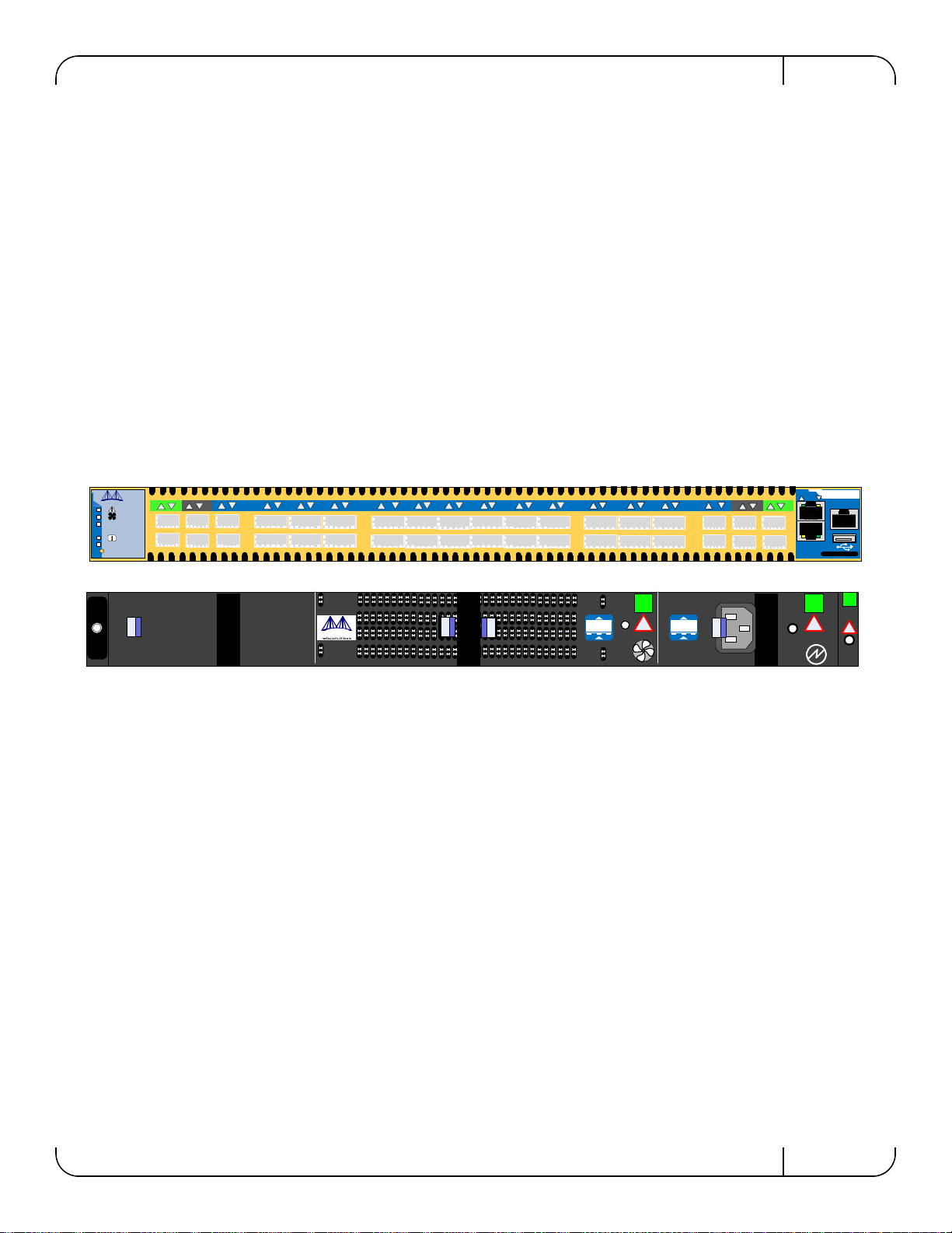
Figure 1: Connector and Power Side Panels
Full Feature List
• Reference traces SMA and mini-SMP
• Compliance ports SMA and mini-SMP
• 2 ports connect to mini SMP connectors for SI testing
• 24 QSFP ports
• 1 PSU
• 8 SFP+ ports
• 24 FDR (56Gb/s) ports in a 1U switch
• IBTA 1.3 and 1.21 complaint
• SDR/DDR/QDR/FDR10/FDR link speed
• FDR10 supports 20% more bandwidth over regular QDR using the same cables/connec-
tors
• All ports can be set to gateway ports connecting to 40GigE (over QSFP) or 1/10GigE
(over QSA)
• 4.032 Tb/s aggregate data switching capacity with ultra low latency
MT51336-EN-EVB
CONSOLE
MGT
RST
UID
PS1
5678910 11 12 13 14 15 16 17 18 19 20 21 22 23 24 25 26 27 28 29 30 31 32 35 36
33 34
124
3
Mellanox !!
OK
OK !
!
OK
I2C
Overview
Rev 1.5
Mellanox Technologies
10
1.1 Management CPU
The EVB comes with a Power PC 460E CPU for management. It also comes with a PCIE/1GbE
Extender that allows the user bypass the management CPU and to connect directly to the chip.
1.2 PCIE/1GbE Extender Kit
The Power PC management module can be removed and in its place a PCIE/1GbE extender can
be installed. When the Management module is removed the EVB becomes externally managed.
The PCIE/1GbE extender kit contains the system side board and the server side board.
The board has four connectors:
The server side board in the kit, gets inserted in a server. Connect the card into a 8X or 16X PCI
slot. This card has 3 ports:
When the PCIE/1GbE Extender is used the Power PC is removed from the sys-
tem and none of the management interfaces on the connector side will work.
When the Power PC is removed the switch/ EVB becomes unmanaged and
does NOT need Initial configuration.
Interface Description
CX4 connector for clocking and reset
2 QSFP connectors one is blue, one is green
• The green one goes from the green labeled connector on the EVBduaghter board to the
green label on the server side card included in the kit.
• The blue one goes from the blue labeled connector on the EVBduaghter board to the blue
label on the server side card included in the kit.
Server Side board a card that gets inserted into the server X8 PCI slot.
Use only one option the PCIE or the Ethernet, do not use both
RJ 45 connector for management through an ethernet port
Interface Description
CX4 connector for clocking and reset
2 QSFP connectors one is blue, one is green
• The green one goes from the green labeled connector on the EVBduaghter board to the
green label on the server side card included in the kit.
• The blue one goes from the blue labeled connector on the EVBduaghter board to the blue
label on the server side card included in the kit.
SwitchX Switch EVB Hardware User Manual Rev 1.5
Mellanox Technologies 11
1.2.1 PCIE Extender Kit
This option allows the EVB to be managed through the server. This is done with three cables
connecting the EVB to the Server. One cable is for clocking and reset and two cables are for data
TX and RX.
1.2.2 1GbE Extender Kit
The PCIE extender allows for remote management through the 10/100/1000Mb RJ45 Ethernet
connection on the EVB Extender side board. This is connected to any standard Ethernet port fab-
ric management port.
1.3 Compliance Ports
Ports 3 and 4 and 33 and 34 are connected to the chip. These are compliance ports and go to the
SMA/mini-SMP interfaces. Ports 3 and 4 are SMA ports and ports 33 and34 are mini-SMP ports.
Use port 4 for compliance and use port 2 as the reference port. Compliance ports are the worst
case loss (for all of the on board connectors) through the channel. They are designed to have an
insertion loss of 5.5dB as defined in SFF-8431.
See Figure 12 on page 22 for identifying the trace and compliance ports. See Figure 35 on
page 45 and Table 7 on page 46 for locations and numbering of the trace and compliance port
board connections.
1.4 Reference Traces
Ports 1 and 2 and 35 and 36 are not connected to the chip. These are reference ports and go to the
SMA/mini-SMP interfaces. See Figure 35 on page 45 and Table 7 on page 46 For locations and
numbering of the board connections. Ports 1 and 2 are SMAports and ports 35 and36 are mini-
SMP ports.
These reference traces are designed to have identical insertion loss as the corresponding compli-
ance ports, and those traces are routed in the same geometry and length as the traces of the com-
pliance ports.
1.5 Serial Number and Product Version Information
The Serial number and GUID for the switch and the MAC for the Management PC are found on
the pull out tab below the USB interface connection.
As of this revision only port 4 is verified at the proper designed insertion loss.
Use port 4 for compliance.

Overview
Rev 1.5
Mellanox Technologies
12
Figure 2: Pull Out Tab
S/N: MT1117X00014
P/N: MT51336-EN-EVB
MAC: 0002C927051C
Made in IL
MGT 1: 00:02:C9:11:A2:01
MGT 2: 00:02:C9:11:A2:02
Rev:A1

SwitchX Switch EVB Hardware User Manual Rev 1.5
Mellanox Technologies 13
2 40 Gb/s Ethernet
Each QSFP port is capable of up to 40GigE and SFP+ ports except for the Reference ports can
run at 10GigE/1GigE. Ports 1 and 2 and 35 and 36 are not connected to the chip.
All ports are capable of virtual switching (VEPA+). All usable virtual switching ports are
grouped together.
The port protocol can only be obtained from the management interface.
40 Gb ETH is only guaranteed to work with approved Mellanox Cables.

FDR
Rev 1.5
Mellanox Technologies
14
3FDR
The SwitchX® EVB supports FDR, a pre-standard InfiniBand data rate, where each lane of a 4X
port runs a bit rate of 14.0625Gb/s with a 64b/66b encoding, resulting in an effective bandwidth
of 54.54Gb/s. The FDR physical layer is an IBTA specified physical layer using different block
types, deskew mechanism and framing rules.
SwitchX™ also supports FDR10, a non-standard InfiniBand data rate, where each lane of a 4X
port runs a bit rate of 10.3125Gb/s with a 64b/66b encoding, resulting in an effective bandwidth
of
40Gb/s.
FDR10 supports 20% more bandwidth over regular QDR using the same QSFP cables/connec-
tors.
Both FDR and FDR10 support Forward Error Correction (FEC), as described in IEEE 802.3ap
chapter 74.
FDR10 is only guaranteed to work with approved Mellanox ConnectX-3 adapters.

SwitchX Switch EVB Hardware User Manual Rev 1.5
Mellanox Technologies 15
4 Basic Operation and Installation
4.1 Switch Platform Hardware Overview
Figure 4 shows the power side panel and connector side panel views of the switch EVB.
Figure 3: Connector and Power Side Panel
The figure shows port configurations for the switch systems, including:
• 2 – Ethernet RJ45 connectors
• 1 – RJ45 connector for connecting to a host PC (CONSOLE)
• 1 – USB connector
• 24 QSFP ports
• 12 SFP+ ports
• various switch, port, fan and power status LEDs
Figure 4: Power Side Panel
• 1 – hot-swap fan module
• 1 – power supply unit
• 1 – I2C connector
• various switch, port, fan and power status LEDs
All connectivity except for power cords is via the connector side panel. All connectors can sup-
port active cables.
MT51336-EN-EVB
CONSOLE
MGT
RST
UID
PS1
5678910 11 12 13 14 15 16 17 18 19 20 21 22 23 24 25 26 27 28 29 30 31 32 35 36
33 34
124
3
Mellanox !!
OK
OK !
!
OK
I2C

Basic Operation and Installation
Rev 1.5
Mellanox Technologies
16
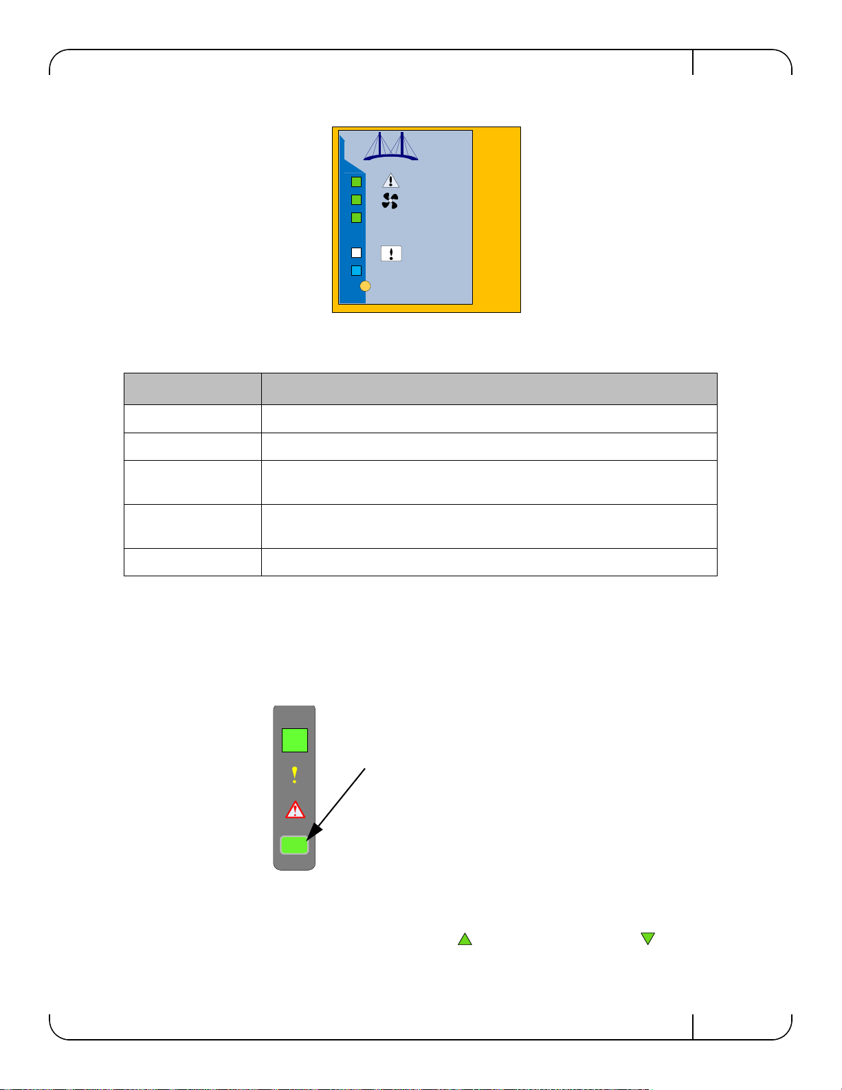
4.1.1 Status LEDs
4.1.1.1 System Status Indicators
The System Status indicators ( ) are located to the left of the connectors on the connector
side panel, and on the power side at the far right. Both of these LEDs give identical information.
The system status indicators should display as follows:
• When the switch is plugged in, within three minutes the STATUS LED should light up
green.
• The PSU LED should light up green. If the PSU LED is not green, this indicates a prob-
lem with the power supply. The switch is operational only if the PSU LED is green.
• The FAN LED should light up green. If the FAN LED shows red, troubleshoot the fan
module.
As long as there is power to the switch and the switch is booted up and running, the
status LED should be green.
If the STATUS LED shows red after three minutes, unplug the switch and call your
Mellanox representative for assistance.
If the switch shuts down due to over temperature, unplug the switch, wait 5 minutes
and replug in the switch. For more information See “Troubleshooting” on page 54.
OK
RST
UID
PS1
Power side
status LED Connector side
status LED
Green – OK
Yellow – a fault in the sys-
tem
Red – Major Fault or
Fatal Error
Led Color shows the
switch status
SwitchX Switch EVB Hardware User Manual Rev 1.5
Mellanox Technologies 17
Figure 5: Power, Fan, and System LEDs
4.1.1.2 Power Side Panel System LED
On the right side of the power side panel is a single system LED that displays the health of the
switch. This indicator is the same as the system status indicator on the other side of the switch.
The LED assignment is as in Table 2.
Figure 6: System Health LED
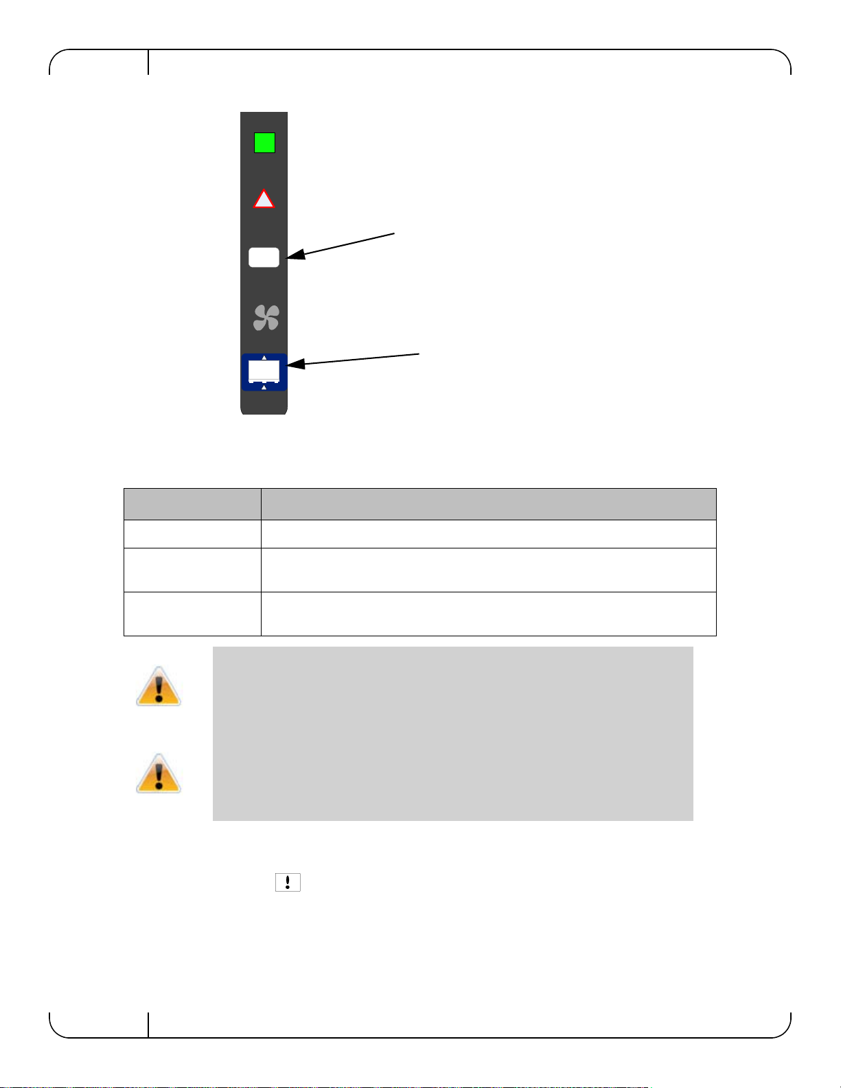
4.1.1.3 Port Connector LED Assignment
Above the ports are two LEDs one for the upper port and one for the lower port . The fol-
lowing table shows the port status according to the LED indication.
Table 2 - System Status LED Configurations
LED Configuration STATUS/ System Health LED
Solid Green OK – The system is up and running.
Flashing Green The system is booting up.
Solid Yellow Error – A fault in the system, most likely
the firmware did not BOOT properly.
Solid Red Major Error – Possible damage can result to the switch. Turn off immediately.
e.g. bad firmware, can’t boot, overheated
Off Off – The system has no power.
RST
UID
PS1
OK
This is a three color ED
Green — OK
Yellow — Fault in the system
Red — Major fault

Basic Operation and Installation
Rev 1.5
Mellanox Technologies
18
4.1.1.4 Power Supply Status Indicators
The switch EVB is only available with one installed Power Supply Unit.
Figure 7: Power Side Panel
The power supply unit (PSU) is located on the right side of the power side panel. The PSU has a
single 2 color LED on the right side of the PSU, that indicates the internal status of the unit.
Table 3 - Connector Physical and Logical Link Indications
LED Status LED Description
Off No power to the port
Solid Green Logical link up
Flashing Green Data activity flashing speed is proportional to data transfer speed
Solid Orange Physical link up
Flashing Orange A problem with the physical link. Usually the SM is down or not enabling the
port.
Fan Unit
Mellanox !!
OK
OK !
!
OK
I2C
Power Supply Unit
PSU1 status LED
Fan status LED

SwitchX Switch EVB Hardware User Manual Rev 1.5
Mellanox Technologies 19
Figure 8: PSU Status LEDs
4.1.1.5 Fan Status Indicators
The indicator is located to the left of the connectors on the connector side panel.
Figure 9: Fan Status LED Connector Side
The LED indicator on the Fan Module is on the right side of the module.
Table 4 - PSU Status LED Configurations
LED Color Status
Solid Green OK – The Power supply is delivering the correct voltage. 12VDC
Solid Red Error – The PSU is not operational
Off Off – There is no power to the system .
!
OK
This is a two color LED
Green — OK
Red — Major fault
Off — No power to the system
Fan air flow indicator
RST
UID
PS1
This is a two color LED
Green — OK
Red — Major fault
Off — No power to the system
Basic Operation and Installation
Rev 1.5
Mellanox Technologies
20
Figure 10: Fan Status LED Power side
The following fan status conditions are possible:
4.1.1.6 Bad Port LED
The Bad Port indicator is located on the left side of the connector side panel of the unit. The
following Bad Port conditions are possible:
Table 5 - Fan Status LED Configurations
LED Configuration FAN LED
Solid Green OK – The system is up and running.
Solid Red Error – One or more fans is not operating properly. The system should be powered
down and troubleshoot the fan module.
Off Off – The fan unit is not receiving any power. Check that the fan unit is properly
and completely inserted.
All fans must be operating while the power supply is plugged in.
If the switch shuts down due to over temperature, unplug the switch, wait 5 minutes
and replug in the switch. For more information See “Troubleshooting” on page 54.
!
OK
This is a two color LED
Green — OK
Red — Major fault
Off — No power to the system
Fan air flow indicator
Other manuals for MT51336-EN-EVB
1
This manual suits for next models
1
Table of contents
Other Mellanox Technologies Motherboard manuals


