MEN G101 User manual

User Manual
2015-09-2920G101-00 E2
G101
3U CompactPCI Serial Managed Industrial Ethernet Switch with
Uplink

G101 - 3U CompactPCI® Serial Managed Industrial Ethernet Switch with Uplink
20G101-00 E2 2015-09-29
Page 2
G101 - 3U CompactPCI®Serial Managed Industrial Ethernet Switch
with Uplink
A flexible switch in a common modular format
The G101 is a managed 3U flexible multiport Gigabit Switch, with a 29 GBit/s Switch
matrix, implemented as a CompactPCI® Serial board. It occupies one system slot or one
peripheral slot using a 4 HP front panel with two Gigabit Ethernet ports on
RJ45 connectors and one 2.5 Gb SFP cage. Alternatively, the G101 can be supplied with
three M12 connectors on the front panel.
High speed, high efficiency and extensive protocols
The G101 guarantees high speed, high efficiency and a large software pool for various
protocols like security, time synchronicity, stability, as well as for temperature needs. The
switch supports EEE (Energy Efficient Ethernet) as a standard on all ports, IEEE1588v2 on
ports 1 to 12 and SyncE (synchronous Ethernet) as an option. Together with the new
backplane concept for MEN switches and routers, it allows high flexibility in network
applications and management.
Various connection possibilities due to various port options
The G101 either features three Ethernet ports on the front and up to 22 ports on the
rear, or alternatively all 25 ports on the rear. These include 12 ports with integrated 10/
100/1000 Mbit/s copper PHYs. In addition the G101 features a high performance port
with up to 2.5 Gbit/s for a SFP pluggable module to support a high speed uplink.
Increased reliability thanks to built-in test mechanisms
The switch is fault tolerant and restores itself on its own: If a link is temporarily
unavailable, frames can be sent via backup/redundant links (spanning tree protocol/link
aggregation) and no data loss occurs. Its built-in test mechanisms make the G101 an
even more reliable component in the communication system.
Rugged and compliant to railway standards
The railway Ethernet switch is specifically designed for rugged mobile communication
systems and fully compliant with the EN 50155 railway standard, qualified for a -40 to
+85°C operation temperature and ready for coating.

Diagram
20G101-00 E2 2015-09-29
Page 3
Diagram
5GbEthernet
GigabitEthernet
FVitesseVSC7429
Processor
GigabitEthernet
F
GigabitEthernet
F
DDR2
SDRAM
SGPIO
4GbEthernet
4GbEthernet
2xQSGMII
PHY
QSGMII
P1
P2
P4
P5
P6
RJ45
RJ45
SFP
R
R
R
R
R
Reset
F
FFront
Rear
R
Options
RS232
F
3GbEthernet
SPGIO
PSU:
DC/DC
16VDCmax.
FPGA

Technical Data
20G101-00 E2 2015-09-29
Page 4
Technical Data
Supported Port Types
The following configurations are available:
-RJ45: 12x 1 Gbps + 1x 2.5 Gbps (2x 1 Gbps + 1x 2.5 Gbps on front) with "on-the-Fly"
SFP detection support (Model: 02G101-00)
-M12: 12x 1 Gbps CU Ports (3x 1 Gbps M12 on front) (Model: 02G101-01)
Enhancements:
-Gigabit Copper Ethernet line card with 4x 1 Gbps ports, available via RJ45 or M12
connectors at the front panel
-Gigabit Copper Ethernet PHY line card with 4x 1 Gbps ports, available via RJ45 or
M12 connectors at the front panel
-Gigabit Ethernet SFP PHY line card with 4x 1 Gbps ports, available via SFP cages at
the front panel
-Supports up to 6 line cards, depending on configuration, with optional PoE
Tested SFP Types
CISCO GLC-SX-MM, 1 Gbps BASE-SX, 220/500 m, 0 to +70×C
AVAGO ABR-5710 ALZ, 1 Gbps BASE-SX, 250/550 m, -40 to +85×C
Finisar FTLF8519P3BTL, 1 Gbps BASE-SX, 300/500 m, -40 to +85×C
Finisar FTLF1318P3BTL, 1 Gbps BASE-LH, 10 km, -40 to +85×C
Finisar FTLF1518P1BTL, 1 Gbps BASE-ZX, 80 km, -40 to +85×C
AVAGO ABR-57R5APZ, 4.25 Gbps BASE-SX, 300 m @ 2.125 Gbps, -10 to +85×C
Switching Matrix
Max. Throughput: 29 Gbps / 40 Mpps@64 Bytes per packet
Max. Mac Address Table Size: 8192
Switching Algorithm. TCAM
General Network Support
IPv4 and IPv6 Forwarding and Management
IPv6 Ready Logo Phase 2
Ports and Port Control
Energy Efficient Ethernet (IEEE 802.3az)
ETH Signal Equalization and Power Control
Port state (admin), speed, duplex mode and flow control
Port frame size (Jumbo Frames: 9216 Bytes/Packet max)
Port status (link monitoring) and statistics (MIB counters)
Port VeriPHY (cable diagnostics), ActiPHY? and PerfectReach
Inband management (VRAP)
User Configuration Interfaces
http/HTTPs, Telnet, SSHv2, Console (USB)

Technical Data
20G101-00 E2 2015-09-29
Page 5
Switch Management and Monitoring
OAM
-Link OAM: IEEE 802.3ah
-Flow OAM (ingres, egres): IEEE802.1ag, ITU-T Y.1731 Down-MEP, ITU-T Y.1731 Up-
MEP, ITU-T Y.1731 MIP,
-SMAC/DMAC Swap
-OAM Performance Monitoring MEF35 Phase 1
-Redirect back to arrival port debugging feature
SNMP Management v1, v2c, v3 (RFC 1212, 1901-1908, 3411-3418)
SNMP v1 Traps (RFC 1157) with multiple destinations
LLDP (IEEE 802.10AB-2005/LLDP)
TIA 1057 LLDP-MED extensions
CDP (Cisco Discovery Protocol)
RMON Group 1, 2, 3 and 9(RFC 2819)
Syslog (RFC 5424)
sFlow (RFC 3176)
Port and Flow Mirroring (10 Ports max)
Fallback Firmware
Configuration Management
TFTP (RFC 1350)
Import/Export via Web-Interface
Configuration download and upload: XML and inidustry-standards format
Redundancy and Flow Control
Static Link Aggregation
Link Aggregation Protocol (LACP: IEEE 802.3ad)
Back Pressure Flow Control (IEEE 802.3X)
Spanning Tree (STP: IEEE 802.1 D)
Rapid Spanning Tree (RSTP: IEEE 802.1w)
Multiple Spanning Tree (MSTP: IEEE 802.1s)
BPDU Restrict and Guard Role (IEEE 802.1w Root Guard)
Ring and Linear Protection Switching (ITU-T G.8031 and G.8032)
-1+1 port protection
-1:1 port protection
-1:n port protection
Connectivity Fault Protection (IEEE 802.1ag/ITU-T Y.1731
Loop Protection
Filtering
Unicast, Multicast and Broadcast Traffic/broadcast storm control
Basic ingres limiter
Dynamic ARP Inspection (RFC 2132 / MAC address based filtering)
IP Source Guard (draft-baker-sava-cisco-ip-source-guard-00)
DHCP Snooping (RFC 2132)
IP MAC binding
IP MAC binding dynamic to static

Technical Data
20G101-00 E2 2015-09-29
Page 6
Security
Static L2 Port Isolation
Port based RADIUS and internal MAC Authentication (IEEE 802.1X)
RADIUS accounting (RFC 2866ff)
Single and Multiple IEEE 802.1X
VLAN and QOS assignment
TACACS+ (RFC 1492)
MAC address flood prevention (MAC address table limitation)
Web and CLI Authentication
Switch Access Authorization (15 levels)
ACLs for filtering, policing and port copy
VLAN
Max. number of VLANs: 4096
VLAN Tagging and Trunking (IEEE 802.1Q)
Supported VLAN Types:
-Private Static VLAN (RFC 5517)
-MAC, Protocol, IP-Subnet and Port based VLAN (IEEE 802.1Q)
-VOICE VLAN (IEEE 802.1Q, IEEE 802.1P)
VLAN Translation (IEEE 802.3ad)
GVRP VLAN registration (IEEE 802.1Q)
Multiple VLAN registration protocol (MVRP: IEEE 8021.1ak)
Guest VLAN Isolation
Multicast
Max. number of IGMP Groups: 8.000 for Layer 2 and 8.000 for IPv4/IPv6
IPv4 Internet Group Management protocol (IGMP) v1, v2, v3
IPv6 Multicast Listener Protocol (MLD) v1, v2 with flooding suppression and router
port handling
Multicast VLAN registration protocol (MVR)
IGMP throttling, filtering, proxy and leave proxy
MRP/GMRP GARP Multicast Registration Protocol (IEEE 802.1ak)
QOS
Active Priority Queues per Port: 8
Class of Service (IEEE 802.1p)
Port and queue egress shaper
Port and User priority mode
Input priority mapping (PCP, DEI to QOS, DP level)
Scheduler Mode (weighted and fair scheduling)
QOS control list (QCL ID, QCL to QCE mapping)
QCE mapping based on ETH-Type, VLAN ID, UDP/TCP port range, DiffServ field and
Tag priority
Random early discard (RED)
Policers: port, service, queue and global/VCAP (ACL)
DiffServ (RFC 2474) and Tag remarking

Technical Data
20G101-00 E2 2015-09-29
Page 7
DHCP
DHCP Server (RFC 2131/ 3132)
DHCP Client (RFC 2131 / 3132)
DHCP Option 82 (DHCP Relay Agent Information Option)
DNS
DNS Client (RFC 2136)
DNS Proxy (RFC 5625)
Synchronization
NTPv4 Client (RFC 5005)
IEEE 1588v2 PTP with one-step and two-step clock
IEEE 1588v2 PTP with redundant masters and timing domains
IEEE 1588v2 boundary, end-to-end and peer-to-peer clock
IEEE 1588v2 unicast and multicast support
Optional Synchronous Ethernet (ITU-T G.8261, G.8262 and G.8264)
Optional combined SyncE and IEEE 1588v2 solution
Layer 2 Bridging
IEEE 802.1D Bridge with source source specific multicast filtering
-auto MAC address learning and aging
-static MAC addresses
IEEE 802.10d Provider Bridge (native or translated VLAN Q-in-Q bridging)
Service enabled Provider Bridge (E-LINE: EPL, EVPL; E-Lan: EP-LAN, EVP-LAN)
Layer 3 support
Classification of Layer 3 flow (SIP, IP Prot, SProt, DProt)
DHCP Option 82 relay
Universal Plug and Play (UPnP)
IPv4 Unicast static routing
Front Interfaces
Ethernet
-Two RJ45 connectors, 1000BASE-T (1 Gbit/s), IEEE802.3 compliant, and one SFP
slot, 1000BASE-T (1 Gbit/s), or
-Three M12 connectors, 1000BASE-T (1 Gbit/s) (X-Coded variants in preparation)
RS232 for configuration (console)
Reset button
Status LEDs
-One board status LED
-Two Ethernet status LEDs
Dongle interface (only on models with M12 connectors)

Technical Data
20G101-00 E2 2015-09-29
Page 8
Rear Interfaces
USB
-One channel, USB2.0 as a console interface for configuration
Ethernet
-Twelve channels 1000BASE-T (1 Gbit/s)
Serial GPIO (SGPIO)
-Compliant with SFF 8485 specification
Supervision and Control
Watchdog
Temperature monitoring
Backplane Standard
CompactPCI® Specification PICMG CPCI-S.0
-System or peripheral slot
Electrical Specifications
Supply voltages
-+5V (-5%) to 16 VDC max.
Power consumption
-Max. 16 W max.
Mechanical Specifications
Dimensions: 3U, 4 HP
Weight: 192 g (model 02G101-00)
Environmental Specifications
Temperature range (operation):
--40×C to +85×C
-Airflow 1.5m/s
Temperature range (storage): -40×C to +85×C
Relative humidity (operation): max. 95% non-condensing
Relative humidity (storage): max. 95% non-condensing
Altitude: -300 m to +2000 m
Shock: 50 m/sð, 30 ms
Vibration (Function): 1 m/sð, 5 Hz to 150 Hz (EN 61373)
Vibration (Lifetime): 7.9 m/sð, 5 Hz to 150 Hz (EN 61373)
Conformal coating on request
Reliability
MTBF: 692.753 h @ 40×C according to IEC/TR 62380 (RDF2000)

Technical Data
20G101-00 E2 2015-09-29
Page 9
Safety
Flammability
-UL 94V-0
Electrical Safety
-EN 50155 (Insulation)
-EN 50155 (Voltage)
EMC
EN 55022 (radio disturbance)
EN 61000-4-2 (ESD Immunity)
EN 61000-4-4 (burst)
Software Support
Firmware for configuration and management

Product Safety
20G101-00 E2 2015-09-29
Page 10
Product Safety
Electrostatic Discharge (ESD)
Computer boards and components contain electrostatic sensitive devices.
Electrostatic discharge (ESD) can damage components. To protect the
board and other components against damage from static electricity, you
should follow some precautions whenever you work on your computer.
Power down and unplug your computer system when working on the
inside.
Hold components by the edges and try not to touch the IC chips, leads,
or circuitry.
Use a grounded wrist strap before handling computer components.
Place components on a grounded antistatic pad or on the bag that came
with the component whenever the components are separated from the
system.
Only store the board in its original ESD-protected packaging. Retain the
original packaging in case you need to return the board to MEN for
repair.
About this Document
20G101-00 E2 2015-09-29
Page 11
About this Document
This user manual is intended only for system developers and integrators, it is not
intended for end users.
It describes the hardware functions of the board, connection of peripheral devices and
integration into a system. It also provides additional information for special applications
and configurations of the board.
The manual does not include detailed information on individual components (data
sheets etc.). A list of literature is given in the appendix.
History
For more information, please see Chapter 4.1 Literature and Web Resources on page
35
Issue Comments Date
E1 First issue 2015-07-31
E2 Added working link to the ETSW firmware manual 2015-09-29

About this Document
20G101-00 E2 2015-09-29
Page 12
Conventions
Indicates important information or warnings concerning the use of
voltages that could lead to a hazardous situation which could result in
personal injury, or damage or destruction of the component.
Indicates important information or warnings concerning proper
functionality of the product described in this document.
The globe icon indicates a hyperlink that links directly to the Internet,
where the latest updated information is available.
When no globe icon is present, the hyperlink links to specific elements and
information within this document.
Italics Folder, file and function names are printed in italics.
Bold Bold type is used for emphasis.
Mono A monospaced font type is used for hexadecimal numbers, listings, C
function descriptions or wherever appropriate. Hexadecimal numbers are
preceded by "0x".
Comment Comments embedded into coding examples are shown in green text.
IRQ#
/IRQ
Signal names followed by a hashtag "#" or preceded by a forward slash "/"
indicate that this signal is either active low or that it becomes active at a
falling edge.
In/Out Signal directions in signal mnemonics tables generally refer to the
corresponding board or component, "in" meaning "to the board or
component", "out" meaning "from the board or component".

Legal Information
20G101-00 E2 2015-09-29
Page 13
Legal Information
Changes
MEN Mikro Elektronik GmbH ("MEN") reserves the right to make changes without further
notice to any products herein.
Warranty, Guarantee, Liability
MEN makes no warranty, representation or guarantee of any kind regarding the
suitability of its products for any particular purpose, nor does MEN assume any liability
arising out of the application or use of any product or circuit, and specifically disclaims
any and all liability, including, without limitation, consequential or incidental damages.
TO THE EXTENT APPLICABLE, SPECIFICALLY EXCLUDED ARE ANY IMPLIED WARRANTIES
ARISING BY OPERATION OF LAW, CUSTOM OR USAGE, INCLUDING WITHOUT LIMITATION,
THE IMPLIED WARRANTIES OF MERCHANTABILITY AND FITNESS FOR A PARTICULAR
PURPOSE OR USE. In no event shall MEN be liable for more than the contract price for
the products in question. If buyer does not notify MEN in writing within the foregoing
warranty period, MEN shall have no liability or obligation to buyer hereunder.
The publication is provided on the terms and understanding that:
1. MEN is not responsible for the results of any actions taken on the basis of
information in the publication, nor for any error in or omission from the publication; and
2. MEN is not engaged in rendering technical or other advice or services.
MEN expressly disclaims all and any liability and responsibility to any person, whether a
reader of the publication or not, in respect of anything, and of the consequences of
anything, done or omitted to be done by any such person in reliance, whether wholly or
partially, on the whole or any part of the contents of the publication.
Conditions for Use, Field of Application
The correct function of MEN products in mission-critical and life-critical applications is
limited to the environmental specification given for each product in the technical user
manual. The correct function of MEN products under extended environmental
conditions is limited to the individual requirement specification and subsequent
validation documents for each product for the applicable use case and has to be agreed
upon in writing by MEN and the customer. Should the customer purchase or use MEN
products for any unintended or unauthorized application, the customer shall indemnify
and hold MEN and its officers, employees, subsidiaries, affiliates, and distributors
harmless against all claims, costs, damages, and expenses, and reasonable attorney fees
arising out of, directly or indirectly, any claim or personal injury or death associated with
such unintended or unauthorized use, even if such claim alleges that MEN was negligent
regarding the design or manufacture of the part. In no case is MEN liable for the correct
function of the technical installation where MEN products are a part of.
Trademarks
All products or services mentioned in this publication are identified by the trademarks,
service marks, or product names as designated by the companies which market those
products. The trademarks and registered trademarks are held by the companies
producing them. Inquiries concerning such trademarks should be made directly to those
companies.

Legal Information
20G101-00 E2 2015-09-29
Page 14
Conformity
MEN products are no ready-made products for end users. They are tested according to
the standards given in the Technical Data and thus enable you to achieve certification of
the product according to the standards applicable in your field of application.
RoHS
Since July 1, 2006 all MEN standard products comply with RoHS legislation.
Since January 2005 the SMD and manual soldering processes at MEN have already been
completely lead-free. Between June 2004 and June 30, 2006 MEN’s selected component
suppliers have changed delivery to RoHS-compliant parts. During this period any change
and status was traceable through the MEN ERP system and the boards gradually became
RoHS-compliant.
WEEE Application
Nevertheless, MEN is registered as a manufacturer in Germany. The registration number
can be provided on request.
Copyright © 2015 MEN Mikro Elektronik GmbH. All rights reserved.
The WEEE directive does not apply to fixed industrial plants and tools. The
compliance is the responsibility of the company which puts the product on
the market, as defined in the directive; components and sub-assemblies
are not subject to product compliance.
In other words: Since MEN does not deliver ready-made products to end
users, the WEEE directive is not applicable for MEN. Users are
nevertheless recommended to properly recycle all electronic boards which
have passed their life cycle.
Germany
MEN Mikro Elektronik GmbH
Neuwieder Straße 3-7
90411 Nuremberg
Phone +49-911-99 33 5-0
Fax +49-911-99 33 5-901
E-mail [email protected]
www.men.de
France
MEN Mikro Elektronik SAS
18, rue René Cassin
ZA de la Châtelaine
74240 Gaillard
Phone +33 (0) 450-955-312
Fax +33 (0) 450-955-211
E-mail [email protected]
www.men-france.fr
USA
MEN Micro Inc.
860 Penllyn Blue Bell Pike
Blue Bell, PA 19422
Phone (215) 542-9575
Fax (215) 542-9577
E-mail [email protected]
www.menmicro.com

Contents
20G101-00 E2 2015-09-29
Page 15
Contents
1 Getting Started . . . . . . . . . . . . . . . . . . . . . . . . . . . . . . . . . . . . . . . . . . . . . . . . 17
1.1 Map of the Board . . . . . . . . . . . . . . . . . . . . . . . . . . . . . . . . . . . . . . . . . . . . . . . . . 17
1.2 Integrating the Board into a System . . . . . . . . . . . . . . . . . . . . . . . . . . . . . . . . . 18
2 Initial Configuration . . . . . . . . . . . . . . . . . . . . . . . . . . . . . . . . . . . . . . . . . . . . 19
2.1 Accessing the switch. . . . . . . . . . . . . . . . . . . . . . . . . . . . . . . . . . . . . . . . . . . . . . .19
2.1.1 Web interface . . . . . . . . . . . . . . . . . . . . . . . . . . . . . . . . . . . . . . . . . . . .19
2.1.2 Command line interface (CLI). . . . . . . . . . . . . . . . . . . . . . . . . . . . . . . 19
2.2 Quick Start Guide . . . . . . . . . . . . . . . . . . . . . . . . . . . . . . . . . . . . . . . . . . . . . . . . . 20
2.2.1 Login and reset configuration to factory defaults . . . . . . . . . . . . . . 21
2.2.2 Setting the device hostname . . . . . . . . . . . . . . . . . . . . . . . . . . . . . . . 21
2.2.3 Setting a password for the admin user. . . . . . . . . . . . . . . . . . . . . . .22
2.2.4 Setting the VLAN 1 IP address . . . . . . . . . . . . . . . . . . . . . . . . . . . . . .22
2.2.5 Display and Save Configuration to FLASH . . . . . . . . . . . . . . . . . . . .23
3 Functional Description. . . . . . . . . . . . . . . . . . . . . . . . . . . . . . . . . . . . . . . . . . 26
3.1 Power Supply. . . . . . . . . . . . . . . . . . . . . . . . . . . . . . . . . . . . . . . . . . . . . . . . . . . . .26
3.2 Thermal Considerations. . . . . . . . . . . . . . . . . . . . . . . . . . . . . . . . . . . . . . . . . . . . 26
3.3 Ethernet Interface. . . . . . . . . . . . . . . . . . . . . . . . . . . . . . . . . . . . . . . . . . . . . . . . . 26
3.3.1 Front-Panel Connection . . . . . . . . . . . . . . . . . . . . . . . . . . . . . . . . . . . 26
3.3.2 Ethernet Switch . . . . . . . . . . . . . . . . . . . . . . . . . . . . . . . . . . . . . . . . . . 29
3.4 Reset Interface . . . . . . . . . . . . . . . . . . . . . . . . . . . . . . . . . . . . . . . . . . . . . . . . . . .29
3.5 Service Connector. . . . . . . . . . . . . . . . . . . . . . . . . . . . . . . . . . . . . . . . . . . . . . . . . 29
3.6 CompactPCI Serial Interface . . . . . . . . . . . . . . . . . . . . . . . . . . . . . . . . . . . . . . . . 30
4 Appendix. . . . . . . . . . . . . . . . . . . . . . . . . . . . . . . . . . . . . . . . . . . . . . . . . . . . . . 35
4.1 Literature and Web Resources . . . . . . . . . . . . . . . . . . . . . . . . . . . . . . . . . . . . . . 35
4.1.1 Ethernet. . . . . . . . . . . . . . . . . . . . . . . . . . . . . . . . . . . . . . . . . . . . . . . . . 35
4.1.2 CompactPCI Serial . . . . . . . . . . . . . . . . . . . . . . . . . . . . . . . . . . . . . . . .35
4.1.3 Finding out the Product’s Article Number, Revision and Serial
Number . . . . . . . . . . . . . . . . . . . . . . . . . . . . . . . . . . . . . . . . . . . . . . . . . 36

20G101-00 E2 2015-09-29
Page 13
Figures
Figure 1. Front panels with RJ45 ports and SFP cage (left,) or M12 ports (right). . . . . . 17
Figure 2. Map of the board – top view. . . . . . . . . . . . . . . . . . . . . . . . . . . . . . . . . . . . . . . . . 18
Figure 3. Accessing the help option. . . . . . . . . . . . . . . . . . . . . . . . . . . . . . . . . . . . . . . . . . . 19
Figure 4. Command line interface . . . . . . . . . . . . . . . . . . . . . . . . . . . . . . . . . . . . . . . . . . . . 20
Figure 5. Labels indicating the product’s article number, revision and
serial number . . . . . . . . . . . . . . . . . . . . . . . . . . . . . . . . . . . . . . . . . . . . . . . . . . . . . 36
Tables
Table 1. Login sequence . . . . . . . . . . . . . . . . . . . . . . . . . . . . . . . . . . . . . . . . . . . . . . . . . . . 21
Table 2. Factory defaults sequence . . . . . . . . . . . . . . . . . . . . . . . . . . . . . . . . . . . . . . . . . . 21
Table 3. Sequence for setting the hostname: . . . . . . . . . . . . . . . . . . . . . . . . . . . . . . . . . . 21
Table 4. Sequence for setting the admin password. . . . . . . . . . . . . . . . . . . . . . . . . . . . .22
Table 5. Commands to configure the IP address . . . . . . . . . . . . . . . . . . . . . . . . . . . . . . .22
Table 6. IP address sequence . . . . . . . . . . . . . . . . . . . . . . . . . . . . . . . . . . . . . . . . . . . . . . . 23
Table 7. Ping command sequence . . . . . . . . . . . . . . . . . . . . . . . . . . . . . . . . . . . . . . . . . . .23
Table 8. Show running-config sequence . . . . . . . . . . . . . . . . . . . . . . . . . . . . . . . . . . . . . . 24
Table 9. Startup-config sequence . . . . . . . . . . . . . . . . . . . . . . . . . . . . . . . . . . . . . . . . . . . .25
Table 10. Signal mnemonics of RJ45 and M12 Ethernet front-panel connectors . . . . . 26
Table 11. Pin assignment of RJ45 Ethernet front-panel connectors . . . . . . . . . . . . . . . . 27
Table 12. Pin assignment of M12 Ethernet front-panel connectors . . . . . . . . . . . . . . . . 27
Table 13. Pin assignment of SFP front-panel connector . . . . . . . . . . . . . . . . . . . . . . . . . .28
Table 14. Signal mnemonics of SFP front-panel connectors . . . . . . . . . . . . . . . . . . . . . . 28
Table 15. Pin assignment of RJ45 Ethernet front-panel connectors . . . . . . . . . . . . . . . . 29
Table 16. Signal mnemonics of front-panel service connector . . . . . . . . . . . . . . . . . . . .29
Table 17. Pin assignment of CompactPCI Serial P1 connector. . . . . . . . . . . . . . . . . . . . . 30
Table 18. Pin assignment of CompactPCI Serial P2 connector. . . . . . . . . . . . . . . . . . . . . 31
Table 19. Pin assignment of CompactPCI Serial P4 connector. . . . . . . . . . . . . . . . . . . . . 32
Table 20. Pin assignment of CompactPCI Serial P5 connector. . . . . . . . . . . . . . . . . . . . . 33
Table 21. Pin assignment of CompactPCI Serial P6 connector. . . . . . . . . . . . . . . . . . . . . 34

Getting Started
20G101-00 E2 2015-09-29
Page 17
1 Getting Started
This chapter provides an overview of the board and some hints for first installation in a
system.
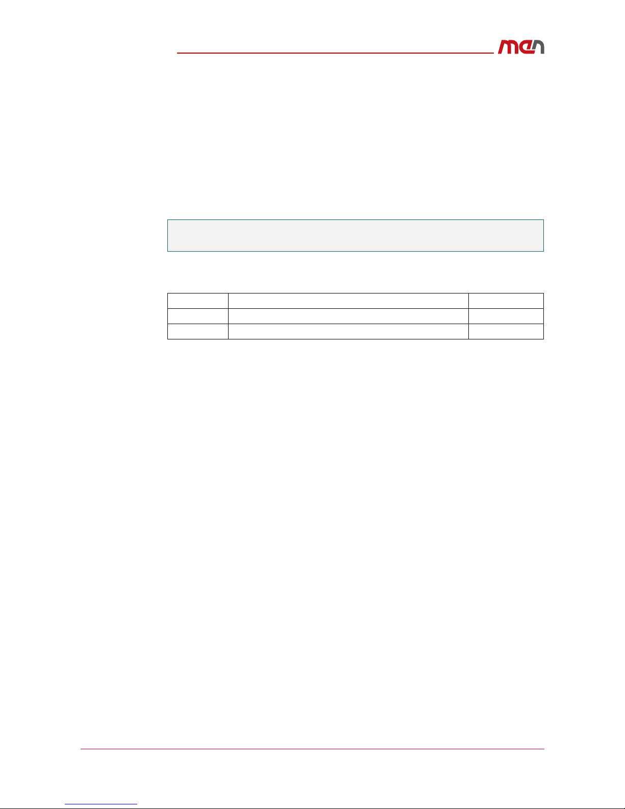
1.1 Map of the Board
Two types of front panels are available, either with RJ45 Ethernet connectors and a SFP
cage, or with M12 Ethernet connectors
Figure 1. Front panels with RJ45 ports and SFP cage (left,) or M12 ports (right)
Serial
®
CompactPCI
1
L
A
3
2
H
S
G101
X1 X2SERVICE X3
Serial
®
CompactPCI
3
2
G101
X1 X2 X3
SERVICE
1
L
A
H
Getting Started
20G101-00 E2 2015-09-29
Page 18
Figure 2. Map of the board – top view
1.2 Integrating the Board into a System
The G101 can be installed in the CompactPCI Serial system slot or any peripheral slot,
and will automatically detect the slot in which it is inserted.
The following check list can be used as a guide when installing the board in a system for
the first time, and with minimum configuration.
System Slot
The G101 can act as the switch for a CompactPCI Serial system when inserting it into the
system slot.
»Power down the system.
»Insert the G101 into the system slot of your CompactPCI Serial system, making sure
that the CompactPCI Serial connectors are properly aligned.
Note: The system slot of every CompactPCI Serial system is marked by a triangle on
the backplane and/or at the front panel. It also has red guide rails.
»Power up the system.
Peripheral Slot
»Power down the system.
»Insert the G101 into the system slot of your CompactPCI Serial system, making sure
that the CompactPCI Serial connectors are properly aligned.
Note: The peripheral slot of every CompactPCI Serial system is marked by a circle
with a plus sign behind it on the backplane and/or at the front panel.
»Power up the system.
P1
P2
P4
P5
P6
GbEtherneton
SFPCageor
M12port
GbEtherneton
RJ45orM12port
GbEtherneton
RJ45orM12port
ConsoleInterface
OnRJ45or
M12port
Initial Configuration
20G101-00 E2 2015-09-29
Page 19
2 Initial Configuration
2.1 Accessing the switch
Once the system has powered up, you can access the switch using its base address with
telnet, ssh, http, https or the service console interface.
The base address of the switch is configured to:
192.168.0.1, netmask 255.255.255.0
The switch is configured to act as DHCP server in the range:
192.168.0.100 - 255 at VLAN 1.
All ports will be opened after the system is started.
The RJ45 front ports have been configured to the rear connectors.
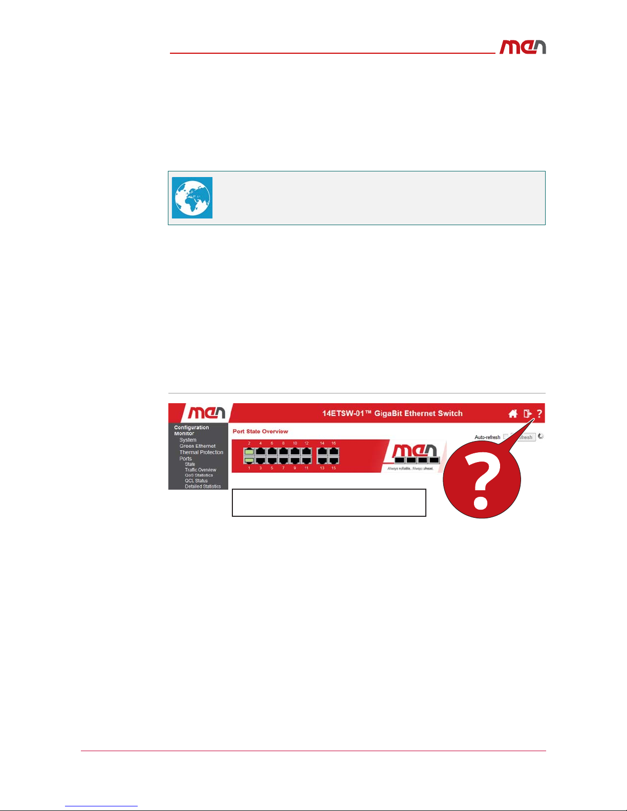
2.1.1 Web interface
The web interface provides an online help option for all configuration sheets which can
be accessed by clicking on the question mark in the top right corner of the screen:
Figure 3. Accessing the help option
2.1.2 Command line interface (CLI)
The CLI is accessible through telnet, ssh or the service console. It is generally compatible
to CISCO/HP CLIs. Help is provided by either using the "TAB" key, or adding a question
mark and the system will indicate the next possible commands.
The connection parameters for the serial virtual console interface are:
115.000 Bps,
8 Bits,
no parity,
no handshake,
1 stop bit
To contact the switch via the backplane interface, install the virtual
connector driver available from the FTDI Chip website.
Example image only - does not necessarily
reflect the actual web interface

Initial Configuration
20G101-00 E2 2015-09-29
Page 20
Figure 4. Command line interface
2.2 Quick Start Guide
The quick start guide is intended to get the user through the initial start-up of the switch
firmware and includes:
Login and reset the configuration to factory default
Setting a device hostname and admin user password
Setting the VLAN 1 IP address
Verifying the connectivity using 'ping'
Displaying the current configuration and saving to FLASH storage
The G101 switch must powered on have a functional computer connection using the
serial console port on the device (115200 baud, no parity, 8 data bits, 1 stop bit, no flow
control).
The computer must be running a terminal emulator such as TeraTerm or
PuTTY on Windows, or Minicom on Linux.
This manual suits for next models
2
Table of contents
Other MEN Switch manuals


Popular Switch manuals by other brands


ZyXEL Communications
ZyXEL Communications ExtraSmart ES-1552 quick start guide

Aube Technologies
Aube Technologies TI071 - Aube by - Solar Programmable Timer... user guide

EUCHNER
EUCHNER CES-A-C5H-EX operating instructions

ATEN
ATEN CS1708A quick start guide

StarTech.com
StarTech.com USB2HDCAPS user guide

StarTech.com
StarTech.com SV831DUSBGB manual