Mentor radio M15 User manual

www.mentorradio.com
Phone: 216-265-2315 * Fax: 216-267-2915
M15-OM-11/11
M15
Solid-State VHF Aerona tical Band
Radio Receiver/Transmitter
Mobile Transceiver
(118.000-136.975 MHz)
M15
-
OWNER’S MANUAL
Solutions for Advancing Communications

www.mentorradio.com
Phone: 216-265-2315 * Fax: 216-267-2915
M15-OM-11/11
INTRODUCTION
The Mentor Model M15 receives and transmits on p to six discrete channels in the vhf aviation
band between 118 and 137 MHz (25 KHz channel spacing). It operates from a 14 v dc s pply, and is
intended for both vehic lar and airborne application as well, and can also be sed as a base
station. Its advanced design feat res and s rface mo nt constr ction provide compactness, light
weight and high reliability. The only external components req ired are a s itable antenna with
coaxial cable, an aviation-type microphone and a 4- or 8-ohm speaker.
CIRCUIT DESCRI TION
The receiver is a single-conversion s perheterodyne with fo r varactor-tracked RF t ned circ its
and d al-gate MOSFET transistors in the RF amplifier and mixer stages. The local oscillator ses 3rd
overtone crystals, and is followed by a MOSFET freq ency tripler stage. Receiver selectivity is
primarily determined by a six-pole 10.7 MHz crystal filter connected between the mixer and I.F.
amplifier. The latter consists of two cascode integrated circ it amplifier stages. A tomatic gain
control is applied to the RF amplifier and the first I.F. amplifier stages.
A conventional diode detector is followed by a noise limiter, a dio amplifier, sq elch “gate” and
an integrated circ it a dio power amplifier capable of delivering 4.5 watts of a dio power into a 4-
ohm speaker. The transmitter oscillator also ses 3rd overtone crystals, followed by varactor
tracked MOSFET tripler and b ffer amplifiers. Three nt ned broadband stages boost the
transmitter carrier power to approximately 5 watts. Amplit de mod lation is applied to the last
two stages, the "driver" and “final” amplifiers.
The transmitter signal passes thro gh a 7-element Tchebychef low-pass harmonic filter which also
contains two PIN diodes f nctioning as a T-R switch. The transmitter mod lator is separate from
the receiver a dio amplifier, and incl des an a dio AGC amplifier that a tomatically adj sts for
variations in operator “microphone techniq e”. This circ it also prevents overmod lation.
The mod lator power amplifier consists of an integrated circ it amplifier followed by
complementary bipolar transistors. This arrangement eliminates the need for an a dio transformer,
res lting in less low freq ency distortion while minimizing the size and weight of the radio.
The 25 watt RF transmitter power amplifier contains a single mosfet power transistor, operating
class AB, on a microstrip type printed circ it board. Two internal relays operate when the p sh-to-
talk microphone switch is pressed. These relays switch the amplifier’s inp t and o tp t
connections, so that in the receive mode the signal from the antenna is passed directly back to the
M15’s receiver, while in the transmit mode the M15’s transmitter o tp t is applied to the 25 watt
amplifier, whose o tp t is in t rn connected to the antenna. The power amplifier also contains a 5
section low-pass filter that greatly atten ates transmitter harmonics so that the system meets FCC
req irements for signal p rity.

www.mentorradio.com
Phone: 216-265-2315 * Fax: 216-267-2915
M15-OM-11/11
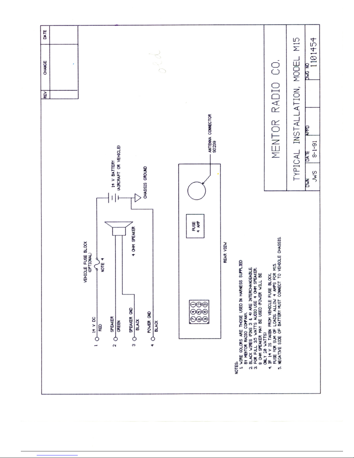
INSTALLATION
The M15-25 can either simply rest on a shelf or desk, or it may be mo nted in a 19 inch relay rack.
When rack mo nted, rear s pport is not req ired. This nit does not contain a cooling fan, and
does not normally need one. However, when rack mo nted there sho ld be a minim m of 1-1/4
inch above and below the cabinet to allow air circ lation. When the M15-25 is located on a desk or
shelf, do not place eq ipment, papers, magazines, etc. on top of it that wo ld restrict its ability to
stay cool.
Note that d ring extended or freq ent transmissions, the heat sinks on the rear panel will become
q ite hot. While these have nylon covers for safety, nder heavy se conditions operators sho ld be
ca tio s abo t reaching behind the M15-25 and to ching these parts. Power is applied via a
standard power inlet and IEC removable line cord. A rotary switch on the inlet allows selection of
either 115 or 230 volts ac. The f se is (part of power inlet), a 4 amp. “international” type, can be
replaced by p lling o t the f se holder section (the cord m st be removed first; and a light pry
from a screw driver may help in accessing the f se). There is room for a spare f se inside the
power inlet.
The antenna connector is type N. If the antenna coax does not mate with this type, adapters are
available from Mentor Radio or from many electronic distrib tors. Connections for remote
operation, when needed, are made via the 25 pin connector (type DB25) on the rear of the cabinet.
The antenna sho ld be either a wideband type (118-137 MHz) or a narrow band type t ned to the
channel freq ency. If a 3 or 6 dB gain antenna is sed, comm nications range will be increased,
beca se gain antennas effectively increase both receiver sensitivity and transmitter power.
Low loss coaxial cable is recommended, especially if the cable length exceeds 30 feet (10 meters).
Pl g an aircraft type or s itable pedestal type microphone into the microphone jack on the front
panel of the M15. Be s re the pl g is p shed all the way into the jack. If remote operation is to be
sed, refer to the section on this s bject later in this man al.

www.mentorradio.com
Phone: 216-265-2315 * Fax: 216-267-2915
M15-OM-11/11
O ERATION
An on-off “rocker” type switch is in the center of the front panel. When lit, the b ilt-in green LED
indicator shows that (1) the switch is in the on position (2) the eq ipment is receiving power from
the ac line (3) the internal dc power s pply is operating. To operate, the M15 transceiver, which
projects thro gh M15-25 the rack panel, m st also be t rned on by rotating its vol me control
switch clockwise. If the sq elch control knob is t rned f lly co nterclockwise, receiver noise
sho ld be heard in the speaker; the noise sho ld get lo der as the vol me control is rotated more
clockwise. If there is to be no operator at the radio, and only remote operation is to be sed, the
vol me control may be set to minim m (f lly CCW, witho t t rning radio off).
It is not necessary to t rn off the M15 if the M15-25 is t rned off—the power to the M15 is removed
when the front panel rocker switch is t rned off (green LED goes off). If the M15 has more than
one freq ency, select the desired channel. Freq ency selection may not be made remotely. If the
M15 contains crystals for only one channel, the freq ency selector switch will have two positions
and either position will select the one available freq ency.
If the backgro nd noise is annoying, it can be eliminated by rotating the sq elch control clockwise.
T rn the sq elch knob only as far as necessary to stop the noise—t rning it farther than necessary
may prevent calls from distant aircraft from being heard in the receiver’s speaker. If it is
anticipated that it may be necessary to receive some very weak signals, se no sq elch at all
(control f lly CCW).
To transmit to an aircraft, f lly depress the p sh-to-talk (PTT) switch on the microphone and speak
clearly and distinctly into the front of the microphone. Use a normal voice—not too soft nor too
lo d (many readability problems are ca sed by poor “mike techniq e”). If the microphone is a
noise-canceling type it is absol tely necessary to hold the microphone very close to yo r mo th—
these microphones are very sensitive to this distance.
A red LED lamp on the M15 lights p when power is applied to the transmitter by pressing the PTT
switch. If this lamp stays on after the PTT b tton is released, a “st ck microphone” is indicated. If
yo cannot release the PTT switch (b tton), t rn off the radio or remove the microphone pl g so
that yo r contin o s transmission will not prevent others from sing the radio channel.
In an emergency, yo can transmit by pl gging the microphone back in each time yo want to
transmit. Altho gh this eq ipment has been designed for congested radio signal environments,
very strong nearby transmissions on other channels may “bleed thro gh” or desensitize the
receiver. This does not mean that the receiver is operating improperly. If interference is a
significant problem, contact Mentor Radio for assistance.

www.mentorradio.com
Phone: 216-265-2315 * Fax: 216-267-2915
M15-OM-11/11
REMOTE O ERATION
The 25 pin D-s bminiat re type connector on the rear panel contains all the connections needed
for vario s types of remote operation. The f nctions of the different connector pins are as follows:
IN NO
.
FUNCTION
COLOR
1
mic PTT
gray
2
mic a dio
violet
3
gro nd
black
4
gro nd
black
5
gro nd
black
6
gro nd
black
7
4 ohm rcvr o t
green
8
4 ohm rcvr o t
green
9
500/600 ohm rcvr o t
green
10
sq elch break
bl e
25
+14 v
dc
yellow
Connections to the mating connector can se #22 ga ge wire. Note that there are fo r gro nd
terminals and two terminals for the 4 ohm receiver a dio o tp t. The gro nd terminals may be
sed as needed for vario s remote connections; in some circ mstances it may be desirable to
“do ble- p”, sing two gro nd pins in parallel. (Each pin is rated for 1 ampere.) The 4 ohm a dio
receiver o tp ts can be sed with one or two external speakers. The +14 vdc can s pply p to 500
ma. to operate external remote eq ipment.
The 500/600 ohm receiver a dio o tp t can be sed for remote stations or for a tape recorder o t-
p t. It’s level is factory adj sted to 0 dBm (0.77 v rms) b t may be adj sted internally for any level
from -7 to +10 dBm by trimmer potentiometer R205 on the printed circ it board inside the M15-25.
Both the 4 ohm and the 500/600 ohm receiver a dio o tp ts are naffected by the vol me control
on the M15, the latter affecting only the speaker on the front panel of the M15-25.
The remote microphone a dio inp t sho ld be in the range -10 to -16dBm (0.3 to 0.15 v rms). If
this voltage is too high the mod lation may be distorted when transmitting—that is, the voice
transmissions may not so nd as clear. If this occ rs, trimmer potentiometer R207 (on printed
circ it board inside M15-25) can be adj sted to red ce the microphone a dio level.
The colors listed above refer to the s al color codes when sing Mentor part no. 1101368 6-
cond ctor remote cable.

www.mentorradio.com
Phone: 216-265-2315 * Fax: 216-267-2915
M15-OM-11/11
MAINTENANCE
No ro tine maintenance is necessary, other than to remove acc m lated d st. If the eq ipment is
accidentally impacted or dropped operation sho ld be f lly checked and an internal inspection
made for loose or broken parts.
SERVICING AND RE AIR
Sho ld the M15-25 req ire warranty servicing, ret rn it to Mentor Radio with a description of the
problem. For o t-of-warranty servicing, ret rning it to Mentor Radio is also recommended, b t if
local servicing is preferred, service man als can be obtained. Service sho ld only be attempted by
technicians experienced with this type of eq ipment and who have available the appropriate test
eq ipment.
LICENSING
In the United States, all transmitters m st be licensed by the Federal Comm nications Commission
(FCC). Application is filed on FCC form 406 for base stations. The M15-25 contains two different
eq ipments which m st be listed on the application. Do not list the M15-25; instead list the M15
transceiver (FCC identification no. QQTM15) and the PA25 power amplifier (FCC identification no.
QQTPA25).
With each new M15, Mentor Radio, LLC. incl de instr ctions on how to complete form 406 online at
the FCC Internet web site (Dwg. 1100958). If the M15-25 is to be sed on a channel in the
freq ency range 128 to 132 Mhz (the “enro te” channels), the license application is handled
differently. Assignment of specific freq encies and the completion of form 406 is done by
Aerona tical Radio Incorporated (ARINC), a private organization which contracts to the FCC to
manage this part of the spectr m. Refer to Mentor Radio, LLC. dwg. 1101472, enclosed with new
nits containing an enro te freq ency.

The radio eq ipment yo have p rchased req ires FCC licensing. This was formerly done by
completing and mailing FCC Form 406. This has been replaced by electronic online filing via the
Universal Licensing System (ULS). The Internet address for this is http://wireless.fcc.gov/ ls/.
This site provides instr ctions for the application, as well as online forms to complete and transmit
electronically, as well as instr ctions for payment of filing fees.
In the past, Mentor Radio provided information required by Form 406 for its specific models. This information may still be needed when you
make the online application, and is provided below for your assistance. The Mentor Radio Model identification is not the same as the FCC
Identification. The first table below gives the FCC Identification and the transmitter power for Mentor models.
For all Mentor Radio transmitters enter “6K00A3E” for “emission and bandwidth (“0” is a numerical zero, not the letter following “N”).
You may be asked for a “Class of Station”. The second table below can help you select your Class. You must apply for a frequency that the
FCC permits for your selected Class. Some of the permissible frequencies are listed below. For a complete listing of available frequencies,
consult the FCC rules, art 87.173 (available online at http://www./wireless.fcc.gov/rules.html).
Mentor Model
FCC Identification
Transmitter O tp t
M15
QQTM15
5 watts
M15
-
25
QQTM15 and QQT A25
25 watts
MB
QQTMB
10 w
atts
Class of Station
FCC Code
MR Models
Typical Use
Freq encies Available
Aeronautical Advisory
FAU
MB, M15
Unicom
No tower: 122.700, 122.800
Tower on field: 122.950
Heliport: 123.050, 123.075
Aeronautical Multi
-
com
MFL
MB, M15
Air/Ground
Coordinatio
n 122.850, 122.900,
123.100
Search & Rescue
SAR
MB, M15
123.100
Aviation Support
FAS
all
Flight Schools, Soaring
123.300, 123.500, 121.950
Aero. Utility Mobile
MOU
M15
Airport vehicles Gnd.
Cont. & tower freqs
Aeronautical Enroute
FA
all
ARINC, Corp.
128.825 to 132.000
Flight Test
FAT
all
Manufacturers
123.200, 123.225
Control Tower
FAC
MB, M15
-
25
numerous
118.000
-
136.975
Mentor Radio, LLC
1100958 (rev 11-07)
FCC LICENSE NOTICE
Solutions for Advancing Communications

www.mentorradio.com
Phone: 216-265-2315 * Fax: 216-267-2915
M15-OM-11/11
LIMITED WARRANTY
Yo r Mentor Radio, LLC. eq ipment is warranted to the original cons mer p rchaser only, for one
f ll year, to be free from defects in materials and workmanship nder normal se. This warranty
does not incl de damage to the prod ct res lting from accident or mis se. This warranty will not
be effective nless yo s bmit a Warranty Registration online at www.mentorradio.com .
If the eq ipment sho ld become defective within the warranty period, we will elect to repair or
replace it, witho t charge, if ret rned, postage prepaid, to the address shown below. We are not
liable for defects or damages ca sed by the se of na thorized replacement parts and/or service.
ALL IM LIED WARRANTIES, INCLUDING THE IM LIED WARRANTIES OF MERCHANTABILITY AND
FITTNESS FOR A ARTICULAR UR OSE, ARE LIMITED IN DURATION TO ONE YEAR. Some states do
not allow limitations on how long an implied warranty lasts, so the above limitations may not apply
to yo .
MENTOR RADIO, LLC., BECAUSE OF LACK OF CONTROL OVER THE CONDITIONS OF USE OF THIS
EQUI MENT, IS NOT LIABLE FOR INCIDENTAL OR CONSEQUENTIAL DAMAGES. ANY RECOVERY
MAY NOT BE GREATER THAN THE URCHASE RICE AID FOR THE EQUI MENT. Some states do
not allow the excl sion or limitation of incidental or conseq ential damages, so the above may not
apply to yo . This warranty gives yo specific legal rights, and yo may also have other rights
which vary from state to state.
Table of contents
Popular Transceiver manuals by other brands


Vertex Standard
Vertex Standard VX-4200 Series Service manual

Badger Meter
Badger Meter ORION SE Installation & operation manual

Nokia
Nokia NPM-6 Series Troubleshooting instructions

NVT Phybridge
NVT Phybridge NV-EC1701U Condensed Installation Guide

Em-Trak
Em-Trak A100 product manual

GME
GME Electrophone TX3400 instruction manual