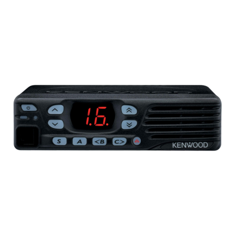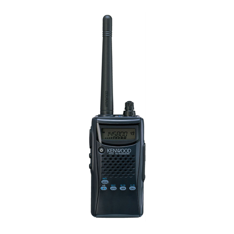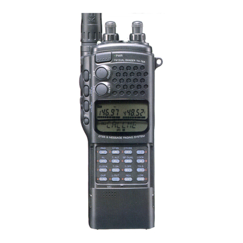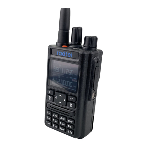
Thank
you
for
purchasing
the
new
TM-3530A/2570A/2550A/2550E/2530A
trans-
ceiver.
Please
read
this
instruction
manual
carefully
before
placing
your
transceiver
in
service.
This
unit
has
been
carefully
engineered
and
manufactured
to
rigid
quality
stan-
dards,
and
should
give
you
satisfactory
and
dependable
operation
for
many
years.
This
Instruction
Manual
covers
the
following
models:
TM-3530A
220
MHz
FM
transceiver
with
KENWOOD
brand.
TM-2570A
144
MHz
FM
transceiver
with
KENWOOD
brand.
TM-2550A
144
MHz
FM
transceiver
with
KENWOOD
brand.
TM-2550E
144
MHz
FM
transceiver
with
KENWOOD
brand.
(Europe
version)
*TM-2550E
144
MHz
FM
transceiver
with
TRIO
brand.
(England
version)
TM-2530A
144
MHz
FM
transceiver
with
KENWOOD
brand.
*in
the
U.K.
the
TM-2550E
is
available
under
the
brand
name
“TRIO”.
The
TM-3530A/2570A/2550A/2550E/2530A
with
KENWOOD
brand
appearing
in
this
instruction
manual
is
not
sold
in
the
U.K.,
as
they
are
made
to
a
different
market
specification.
When
there
are
differences
in
operation
separate
instructions
will
be
given
for
each
model.
Ilustrations
show
the
TM-2550A.
The
following
explicit
definitions
apply
in
this
manual:
Note:
\f
disregarded,
inconvenience
only,
no
risk
of
equipment
damage
or
personal
injury.
Caution:
Equipment
damage
may
occur,
but
not
personal
injury.
4-1,
CONTROLS
AND
THEIR
FUNCTIONS..
4-1-1,
Front
panel
1.
LCD
group....
2.
Keyboard..
4-1-2.
Rear
pane!
..
4-1-3.
Microphone
4-2,
RECEPTION........
4-3.
TRANSMISSION
...
4-3-1.
Precautions
4-4,
MEMORY
4-4-1,
Microprocessor
memory
back-up
4-4-2.
Initial
state
and
reset
of
the
microprocessor.
A.
Initial
state
of
the
microprocessor
From
the
factory
.....scecsseeseseereentneee
15
B.
Microprocessor
reset
..
4-4-3.
Memory
input......
4-4-4,
Paired
channels...
4-4-5,
Priority
channel
select...
4-5.
SCAN...
cccccseteseseeneeneereee
4-5-1.
Memory
scan
from
the
keyboard
..
4-5-2.
Programmable
band-scan
from
the
keyboard
oo...
es
scccessseneesenetsesenertees
4-5-3.
Scan
direction.
4-5-4.
Scan
speed......
4-5-5.
Scan
lockout
(Skip)
4-5-6.
Scan
release
4-5-7.
Priority
channel
scan
(Alert)
4-8.
REPEATER.......ccsscceceeseees
4-6-1.
Automatic
repeater
offset
4-6-2.
Tone
frequency
1.
Setting...
2.
Release...
4-7.
AUTOMATIC
TELEPHONE
NUMBER
TRANSMISSION
SYSTEM
4-7-1.
Telephone
number
programming.
CONTENTS
eFRATURES
3.
03s2.,-2ccdscestedechssieitetsesrscnseesacss
aaieeaneeeery
4
4-7-2,
Storing
a
telephone
channel
in
NOPMaAl
MEMOTY
......sesesesecersesseesesreeeseeene
22
.
SPECIFICATIONS
AND
ACCESSORIES..............
5
4-7-3.
Automatic
telephone
number
2-1.
SPECIFICATIONS.
5
transmission.
2s
2-2,
ACCESSORIES
....
6
4-8.
DCL
(Digital
Channel
Link)
SYSTEM.
23
4-8-1.
DCL
system
description
23
.
INSTALLATION
AND
CONNECTION
.
7
4-8-2.
DCL
system
keyboard
3-1.
INSTALLATION...
7
4-8-3.
Digital
code
entry
3-1-1.
Precautions
.
7
4-8-4.
Code
squelch
3-1-2.
Power
supply.
7
4-8-5,
Channel
linkage
3-1-3.
Mounting
bracket..
8
4-8-6.
Recall.
3-2,
CONNECTION......
8
4-8-7.
Reset
and
return.
3-2-1.
Precautions
.
8
4-8-8.
Call
sign
entry.
oar
3-2-2,
Fixed
station
9
4-8-9,
DCL
SyStem
NOteS
....scessesesceseesesrecnentens
32
3-2-3.
Mobile
.....
9
A.
Battery
)
5.
MAINTENANCE
AND
ADJUSTMENT
B.
Ignition
noise
8
5-1.
GENERAL
INFORMATION
3-2-4.
Antenna
3
5-2.
SERVICE...
5-3.
CLEANING.
.
OPERATION...
.10
5-4.
MICROPROCESSOR
BACK-UP
LITHIUM
BATTERY
REPLACEMENT
..
5-5,
ORDERING
SPARE
PARTS..
5-6.
ADJUSTMENTS........
5-6-1.
Cover
removal.
5-6-2.
Low
power
output..
5-6-3.
Microphone
gain
5-6-4,
DTMF
level...
5-6-5.
Sidetone
and
beeper
level...
5-6-6.
RF
power
meter..............
5-6-7.
TO
(Timer
Operated)
scan
timer...
5-6-8.
Open
channel
search
step
size
SELECTION.
....cceceestnereesensceeteessesseneeesensnee
35
5-6-9.
Microphone
UP/DWN
step
size
and
scan
step
size
selection
5-6-10.
Microprocessor
reset
pins
.
5-6-11.
Call
sign
monitor
test
pins
....
6.
BLOCK
DIAGRAM
36
6-1.
TM-3530A
.
6-2.
TM-2570A....
6-3.
TM-2550A/2530A..
6-4.
TM-2550E
7.
OPTIONAL
ACCESSORIES...
40
7-1.
TU-7
TONE
UNIT......
7-2,
MU-1
MODEM
UNIT
..
7-3,
VS-1
VOICE
SYNTHESIZER
UNIT..
7-4.
OTHER
ACCESSORIES
8.
REFERENCE
8-1.
ANTENNA
.
8-1-1.
Fixed
station
8-1-2.
Mobile
.........
8-2,
MOBILE
INSTALLATION...
8-2-1.
Noise
reduction
8-2-2,
Battery
capacity
...

