Meopta STEREO 35 User manual
www.stereokotoucky.cz
STEREO 35 - operating instructions
type No. 72404
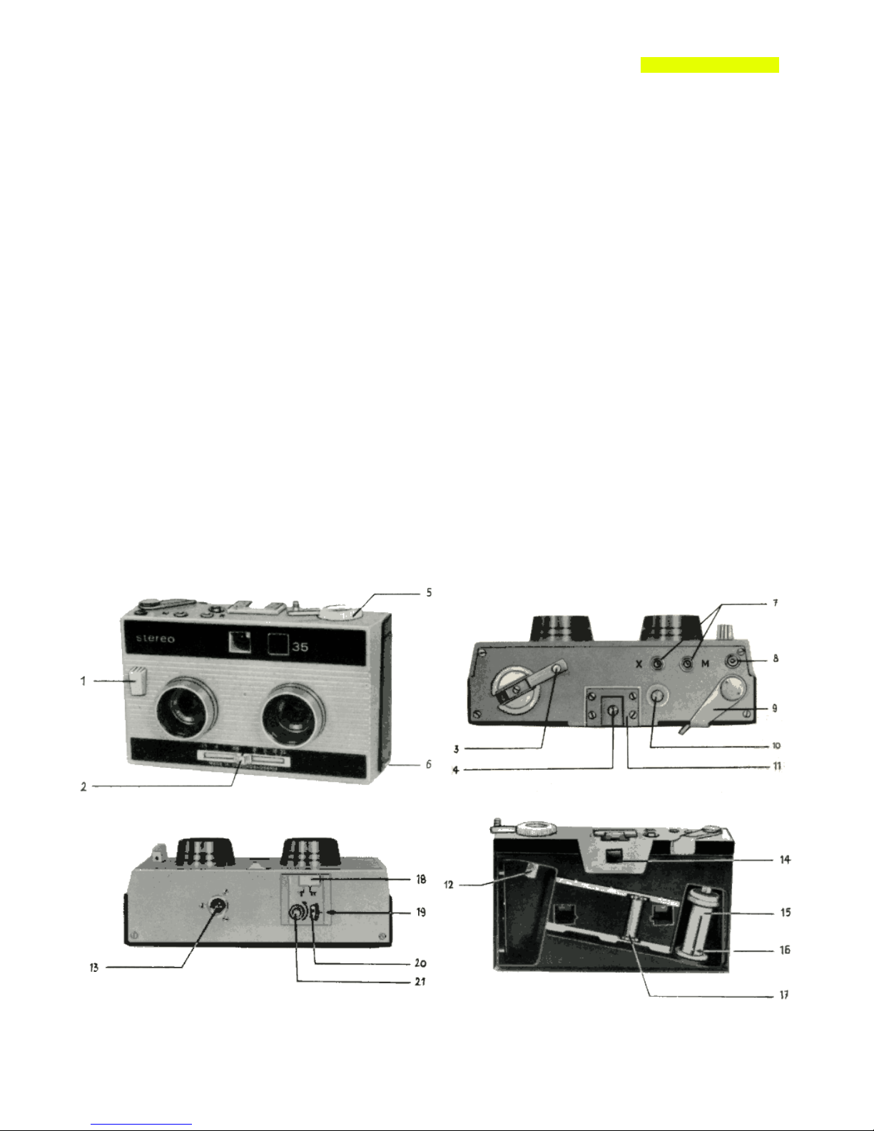
Description of the ca era
The STEREO 35 is a photographic camera for taking stereoscopic pictures.
The individual pictures of the stereo pair have to e punched from the film strip with the aid of a special punch; then
they are ready for insertion into a stereo viewer disc. Viewing the pictures through the MEOSKOP viewer gives full
stereoscopic impression.
For taking pictures y the STEREO 35 camera any standard lack-and-white or colour 35 mm reversal film in a
135-type cartridge may e used. The film travels along a slant path in the camera; this arrangement gives rise to
two rows of 13,5 y 11,5 mm (0,53" y 0,45") pictures. Of each stereo pair the right-hand picture lies in the upper
row, the left-hand picture in the lower row. This arrangement ensures a perfect exploitation of the film area.
The STEREO 35 camera is supplied with two identical lenses of the type MIRAR 3,5/25. No focusing is necessary
due to the large depth of field of these lenses.
The dou le ehind-lens type shutter has two speed settings only: 1/60 s and "B". The shutter takes care of equal
exposure for oth pictures of the stereo pair. Standard PC flash synchronising outlets for flash ul s (M) and for
electronic flash (X) are provided. They are located on the top side of the camera, together with the accessory shoe.
A right frame is superimposed in the viewfinder field, determining the actual taking angle for a most accurate
choice of picture composition.
The film is advanced y means of an advance lever on the top side of the camera. The film advance and shutter
tripping mechanisms are mutually locked, preventing dou le or multiple exposures.
A 3/8" screw socket (13) on the ottom side of the camera can e used for mounting the camera on a tripod when
desired.

www.stereokotoucky.cz
1. Loading the ca era
Pull out the locking ta (6) and open the ack cover. Insert a fresh film cartridge into the left film cham er * so that
its spool engages with the rewind hu (12). If necessary, align the hu slot with the cartridge spool y turning the
rewind kno (5) slightly.
Insert the film leding end into the slot of the take-up spool (15). The spool can e turned in oth directions. Make
sure that the catch (16) engages with one of the film perforations. Turn the take-up spool y a out 3/4 revolution to
the right, until the film lies flat in its track and the teeth of the feed sprocket (17) engage with the film perforations.
Close the ack cover. Turn the ratcheted frame counter wheel (21) in the camera ottom recess until the indicator
(20) shows the triangular mark aligned with the index (19). Push the film advance lever to the right y one full
stroke. Should the lever e locked, push the shutter release (1) on the camera front. This will trip the shutter and
un lock the film advance. After completing the advance stroke, the advance lever returns to its original position
automatically. Proceed this way until the frame counter (20) reads "0". The camera is now ready for the first shot.
2. Exposure
The shutter speeds 1/60 sec. or B can e set y shifting a slide (18) on the camera ottom. The lens diaphragm
apertures are marked on the front side of the camera. The lenses can e stopped down y shifting the slide (2),
always starting at 3,5. The diaphragm mechanisms of oth lenses are linked together. It is advisa le to use a
relia le exposure meter for correct exposure determination.
The STEREO 35 camera can e used for taking pictures of o jects at a distance etween 3 meters (10 ft) and
infinity. Photographing at shorter distances is possi le with the set of appropriate close-up lenses.
3. Taking the pictures
After proper setting of the shutter speed and lens stop the picture can e taken. The camera should e held y oth
hands, pressed against the forehead and the photographed scene followed visually through the viewfinder (14).
The actual photographed area is marked in the viewfinder y a right frame. The camera must always e held
horizontally. The shutter release (1) falls under the right index finger; it should always e pressed steadily, without a
jolt.
A ca le release can e screwed into a socket (8) on the top side of the camera.
It is not possible to take vertical pictures the ca era ust be held horizontally in any circu stances.
4. Futher exposures
After pushing the shutter release (1), the advance lever (9) is un locked. By pushing it to the right one full stroke,
the film is advanced y one frame. At the same time the frame counter advances y one division.
The whole film is exposed in this manner. It is important not to o struct the rewind kno (5) rotation during the film
advance. An excessive force necessary for advancing the film (this may occur near the film end) is an indication of
a locking cartridge; this might cause incorrect picture spacing on the film. Should this situation happen, it can e
corrected y loosening of the film in the cartridge y turning the rewind kno against the arrow slightly.
One standard (36-exposure) cartridge should e sufficient for a out 80 stereo pair exposures. The actual num er
depends on the amount of film used during the loading of the camera.
5. Rewinding of the exposed fil
Full exposure of the whole cartridge load (a out 80 exposures) is indicated y a sudden stiff resistance of the
advance lever (9) against further advance, since the film end is fastened to the cartridge spool. Push the rewind
release utton (10) and rewind the film y turning the rewind kno (5) either directly or y means of the flip-out
crank (3) in the direction indicated y the arrow. Go on rewinding until the whole film is rewound. The end of the
rewinding process can e recognised y a sudden decrease of the rewind force. Open the ack cover and take the
cartridge out.
Should it happen that the film end is torn out of the cartridge, it must e taken out of the camera in total darkness.

www.stereokotoucky.cz
6. Flash pictures
Standard PC outlets for flash synchronisation (7) are located on the top side of the camera. For electronic flash use
the outlet marked "X", for flash ul e use the outlet "M". The "M" synchronising contact is also connected to the ,,hot
shoe" contact. Both X and M contacts are arranged so that the flash fires when the shutter is fully open.
Correct exposure with flash is determined y proper setting of the lens stop. A simple calculation is necessary,
using the formula:
lens stop = flash guide num er : flash-o ject distance
Exa ple: An o ject is 5 meters far from the flash (usually the flash is located on the camera or very near of it). The
flash guide num er given y the flash maker for the film sensitivity used is 20. According to the formula: lens stop =
20 : 5 = 4.
7. Maintenance and handling
Every photographic camera requires careful handling. Guard the camera against moisture, chemical fumes, dust,
mechanical shocks and temperatures in excess of 50°C.
Before loading clean the inside of the camera with a very soft rush. The glass surfaces of the lenses or of the
viewfinder may e cleaned y a clean soft lint-free tissue.
8. Cutting the pictures fro the fil
The pictures that will e inserted into viewer discs must e cut from the film strip with a great degree of precision. It
is a solutely necessary to perform this operation y the special puncher "STEOMAT 35", supplied y the Meopta
factory as a special accessory under the order num er 73942.
9. Special accessories.
a. Eveready case, type No. 73122. The case is made of artificial leather and can e closed y a zipper. A
wrist-strap is attached to the case. The wrist-strap can e fastened to the camera y a screw that fits into
the tripod socket on the camera ottom.
b. Close-up lenses 3 m - 1 m, type No. 70715. They are designated for taking pictures at distance of 3 m - 1
m from camera. Close-up lenses 1 m - 0,6 m, type No. 70716. They are designated for taking pictures at
distance of 1 m - 0,6 m from camera.
c. Filters are supplied in screw-in holders with M 30X0,5 threads. For photographing on colour reversal film
an ultraviolet-a sor ing filter UVO, type 80521 can e used. The following filters can e used for lack and
white reversal films: UV colourless, type 80522; G1 light yellow, type 80523; G2 medium yellow, type
80524; G3 dark yellow, type 80525; GGR1 yellow-green, type 80526; R1 red, type 80528, GR1 green, type
80527; B1 lue, type 80529; N1 light gray, type 80530; N2 medium gray, type 80531. The filters are to e
screved into the threads cut into the front sides of the lens hoods.
d. The STEOMAT 35 punch, type 73942 serves for accurate punching of the finished picture pairs from the
film strip.
e. Viewer discs, type 73929, supplied empty; individual pictures of the stereo pairs, punched from the film
strip y means of the STEOMAT punch can e inserted into these discs.
f. Stereo viewer MEOSKOP accepts the Type 73929 discs for trus stereoscopic viewing of the pictures.
g. Projector DIAMET type No. 76105 is designated for projection of one picture of the stereoscopic pair.
Technical designer of the camera: MACOUN Karel
Shape designer: HEINZ František
Typographical designer of manual: ŘEHÁK Otto
Table of contents
Other Meopta Digital Camera manuals


