INSTALLATION INSTRUCTIONS
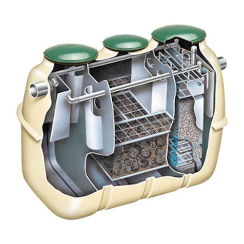
The filter shall be installed, plumb and level. Run water in tank for leveling each layer of filter
mediaexcept top layeroffinesand.Thislayerof fine sand can be leveledsufficientlywith a long
handled rake. Fine sand comes slightly above manhole opening. Leave enough sand near
opening to fill the top layer out after manhole cover has been installed. The first time the filter is
backwashed,thetop ofthe sand will becomelevel.
Close manway cover by tightening the manhole knobs down on the manway yokes. The manway
gasket is aided in sealing tightly by the pressure in the tank. During start-up the gasket may leak
slightly but it should come to a tight seal once operating pressure is reached. After reaching
operating pressure tighten the manway knobs again to insure a seal through subsequent shut-
downs. If the manway gasket leaks at operating pressure, gradually close the valve on the filter
effluent flange (or any valve in the line after the filter) to increase the pressure in the filter tank.
This excess pressure in the filter tank will aid in final sealing of the manway gasket. Again, hand
tighten the knobs of the manway yokes after reaching the highest pressure obtainable.
OPERATING INSTRUCTIONS
Install all face piping including valves, pressure gauges, sight glass, and circulating pump as
shown on drawings, single and dual tank systems (see pages 4 and 5). To allow venting of air
fromthetanksduring start-upandoperation,the air reliefconnectionson thefront andtopofthe
tankshouldbe pipedtoalow pressurepoint in thefiltersystem or to a waste line.Pipingthis to a
surgetank or gutter line will save this water whichis chemically treatedand filtered.Wesuggest
thislineberigidPVCorflexibletubing.Amanualshut-off valve shouldbe mounted on each tank.
This valve should be open during operation, closed on shut-down. Automatic air relief valves
arealsoavailable for air venting.
FILTERS SHOULD BE BACKWASHED WHEN THE FILTER PRESSURE DIFFERENTIAL EXCEEDS
10 - 12 PSI.
FILTER CYCLE:
Open valves V1 and V3 and close valves V2 and V4. Start pump.
Shut off pump, close valves V1 and V3 and open valve V2. Start pump and open valve V4 slowly. The
time from start to full open should be at least 3.0 seconds. Do not exceed backwash flow rate shown
on tank data plate. Continue BAC shing until sigh flow indicator shows clear. This should be
approximately five (5) minutes. At completion of backwash, shut off pump and allow filter beds to settle
three (3) minutes before starting pump on filter cycle.
THREE OR MORE TANK SYSTEMS
Generally, some form of backwash flow rate control is required on multiple tank systems to limit
backwash flow to that required for one tank. Tanks are backwashed one at a time, in
sequence, according to the above procedure. Attempts to backwash all tanks simultaneously
will result in excessive water flowing through the first tank, resulting in disruption of the sand
bed and filter failure. It is not possible to write instructions for the numerous multiple tank
configurations that can be designed. We suggest a piping layout be sent to our office for
comments prior toinstallation.
