Meraki Solar User manual

Meraki Solar
Setup Guide


1
Contents
· System Overview 2
· Understanding the Solar Repeater 4
· Pre-Site Preparation 5
· Configuration on Dashboard 5
· Solar Panel Orientation & Elevation Angle 6
· On-Site Instructions 8
· Install Solar Panel 9
· Pole Mount 10
· Wall Mount 14
· Roof Mount 16
· Mount Solar Repeater 18
· Troubleshooting 20
2
System Overview
The Meraki Solar enables you to provide wireless coverage over large outdoor areas quickly,
easily, and cost effectively. A Meraki Solar system has three components: a solar repeater, a
solar panel, and a solar panel mount kit, each sold separately. The following section describes
each component in more detail.
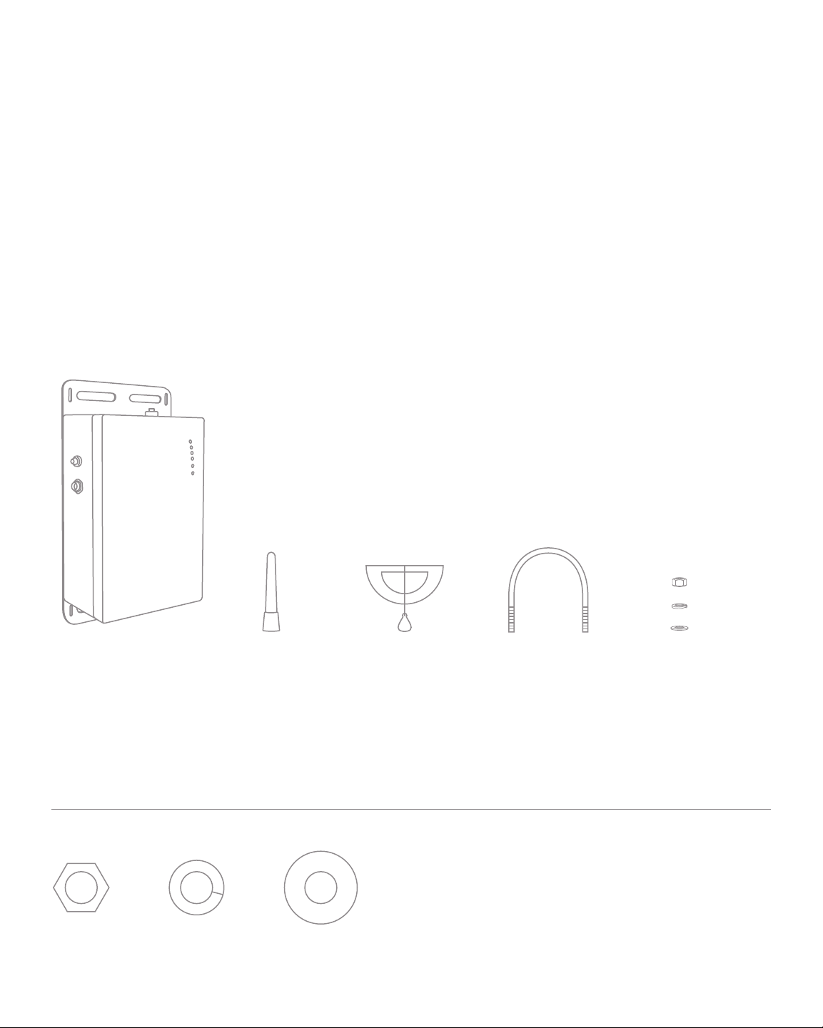
Solar Repeater
The solar repeater is the core of your Meraki Solar system. It contains an 802.11 b/g radio,
battery, and charge controller, all integrated into a weatherproof enclosure. This solar repeater
package contains the following items:
Antenna Inclinometer 2.5" (6 cm) U-bolt 5/16" (8 mm)
Nut & Washer
(includes spares)
Solar Repeater
x6
x6
x10x2
5/16" (8 mm) in actual scale
3
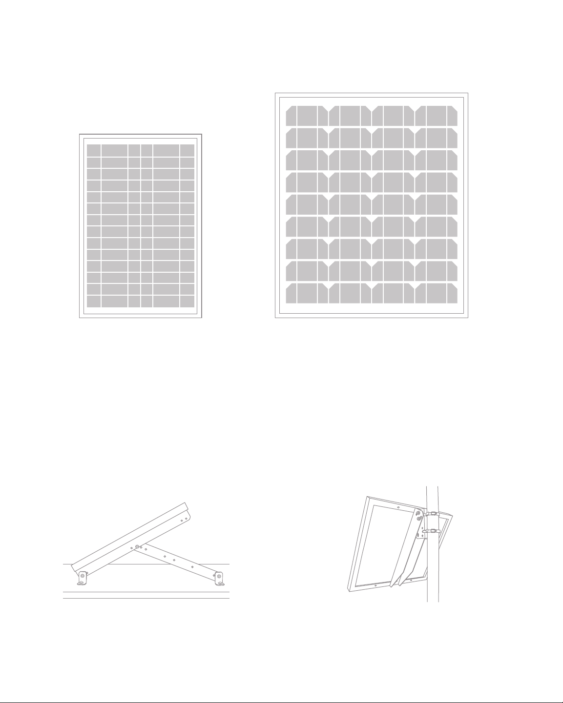
Solar Panel
The solar panel provides the energy needed to power the Meraki Solar system. A 15-foot power cable
comes pre-assembled to your panel. Meraki provides two types of solar panels: 20W and 40W.
Note: If you are providing your own solar panel, you will need to purchase the Meraki Solar Power Ac-
cessory Cable (model number SOL-PWR-CBL) to connect your panel to the solar repeater. You will
also need to follow your 3rd-party solar panel manufacturer’s mounting instructions.
Solar Panel Mount Kit
The solar panel mount kit is used to mount your solar panel to a pole, roof, or wall.
Meraki provides two types of solar panel mount kits: roof/wall mount and pole mount.
20W Solar Panel
Roof Mount Pole Mount
40W Solar Panel
4
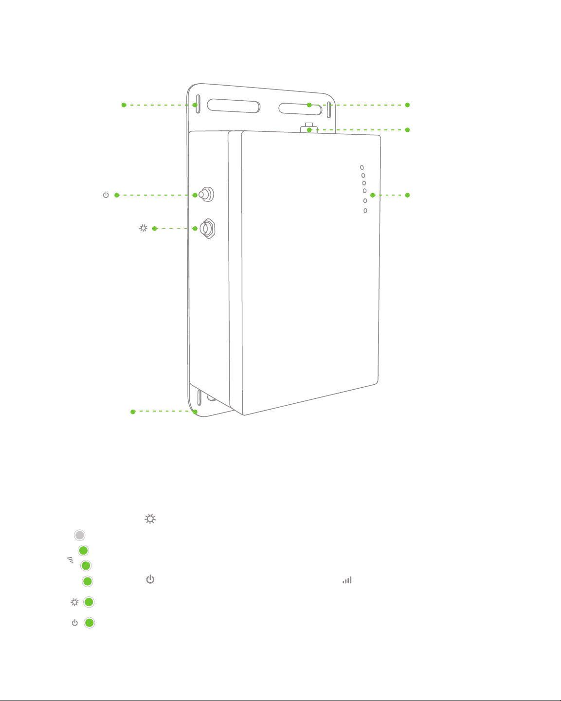
Mounting Backplate
Hose Clamp Slot
LED Indicators
Power Switch
U-bolt Slot
RP-SMA
Antenna Connector
Solar Panel Connector
Understanding the Solar Repeater
Your solar repeater kit has the following features:
Understanding the LED Indicators
Your solar repeater is equipped with a series of LED lights on the front of the unit
to convey information about system functionality and performance:
Solar Panel Status LED
On: Solar panel is powering radio, battery is fully charged
Off: Nighttime or solar panel is disconnected; battery is powering radio
Flashing: Solar panel is powering radio, battery is charging
Radio Power LED
On: Radio is on
Off: Radio is off
Flashes 4x and then turns off
(when power button is first pushed):
Battery charge too low to power radio
Signal Strength
1 Light: Fair, 4 Lights: Strongest
Moving Lights: Searching for signal
5
Pre-Site Preparation
You should complete the following steps before going onsite to perform the installation.
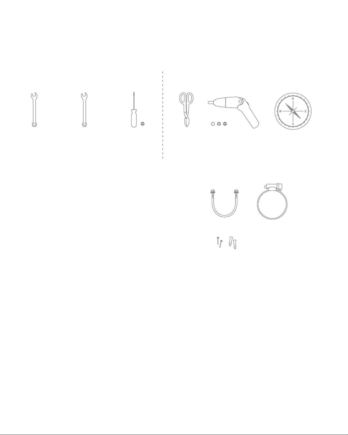
Collect Tools
You will need the following tools to perform your installation.
Collect Additional Mounting Hardware
Solar Repeater – Pole Mount
Your solar repeater fits on poles from 2.0–4.5"(5.1–11.5 cm)
diameter with u-bolts and poles larger than 4.5"(11.5 cm)
with hose clamps. You will need the proper size u-bolt or hose
clamp for your pole. U-bolts for 2.5"(6 cm) poles are included.
Solar Repeater – Wall Mount
You will need screws and anchors appropriate for the wall
surface that you are using.
Solar Panel – Roof/Wall Mount
Hardware for assembling the mount is included, but you will need to acquire any appropriate
hardware for fastening the roof/wall solar panel mount to your desired surface.
Configure your Solar Repeater on Dashboard
Your solar repeater will act as a repeater, but not as a gateway. Therefore, you will need to have an ex-
isting Meraki network that is connected to the Internet. We recommend that you add your solar repeater
to a network on Dashboard before mounting it in the field.
1. Login to http://dashboard.meraki.com. If this is your first time on Dashboard, create an account.
2. Find the network to which you plan to add your solar repeater.
3. Go to the “add nodes” section on the “Configure” tab. In order to register the node, you will need
the serial number of the unit, which looks like Qxxx-xxxx-xxxx, and is found on the bottom of the unit.
4. Finally, go to the map view and place each repeater on the map by clicking and dragging it to the
location where you plan to mount it. You can always modify the location later.
* If you do choose to add the repeater to Dashboard after the installation, make sure to write down
the serial number and MAC address of the unit before installing it.
1/2" (11 mm)
Wrench
Required Recommended
7/16" (13 mm)
Wrench
Flat head
screwdriver
Tin snips Magnetic
Compass
Power screwdriver with
5/16"(8 mm) nut driver,
phillips & flat heads
x2 x2
6
190
180
180
180
180
180
180
180
0
180
180
180
0
0
0
180
180
180
180
180
200
170
170
170
170
190
190
190
190
200
200
140
150
160
160
160
160
170
170
170
170
190
190
190
190
190
190
200
200
180
180
10
10
10
10
10
10
20
20
20
20
30
30
30
30
40
40
40
0
0
20
20
10
10
10
10
10
20
50
50
60
0
0
60
50
50
40
40
40
30
30
30
30
20
20
20
20
20
20
10
10
10
10
20
100
90
80
70
60
50
40
30
20
10
10
70
60
50
40
30
20
10
10
10
20
20
30
40
50
60
70
80
90
170
170
170
190
150
170
160
Determine Correct Solar Panel Orientation and Elevation Angle
You will need to orient your solar panel properly to ensure maximum performance. The two
parameters to keep in mind are the orientation (compass direction) and the elevation angle.
The section below describes how to determine these two parameters.
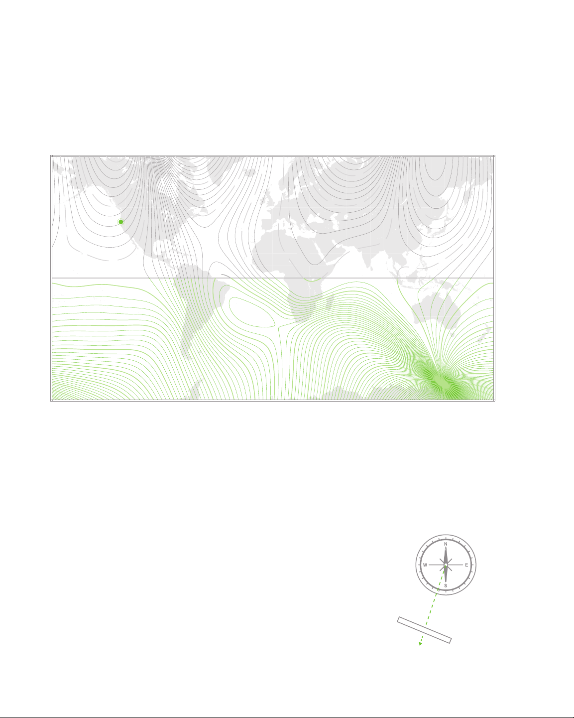
Orientation
If you are in the Southern hemisphere, your solar panel should point to true north
(directly at the geographical north pole). If you are in the Northern hemisphere, point
your solar panel to true south. If you use a magnetic compass to measure your orien-
tation, keep in mind that depending on your location, magnetic north often varies from
true north due to variation in the earth’s magnetic field around the globe. The curved
lines on the world map above show you the compass direction in which you should
point your panel to compensate for this variation.
Example: Let’s say you are in San Francisco, California. Look at the map and find
your location. You will see that San Francisco is located near the curved line that
represents 196°. Therefore, point your panel to 196° as shown on your compass.
Record the correct orientation for your solar panel here:
________________________ degrees
Contour Interval: 2 degrees
196° (True South)
7
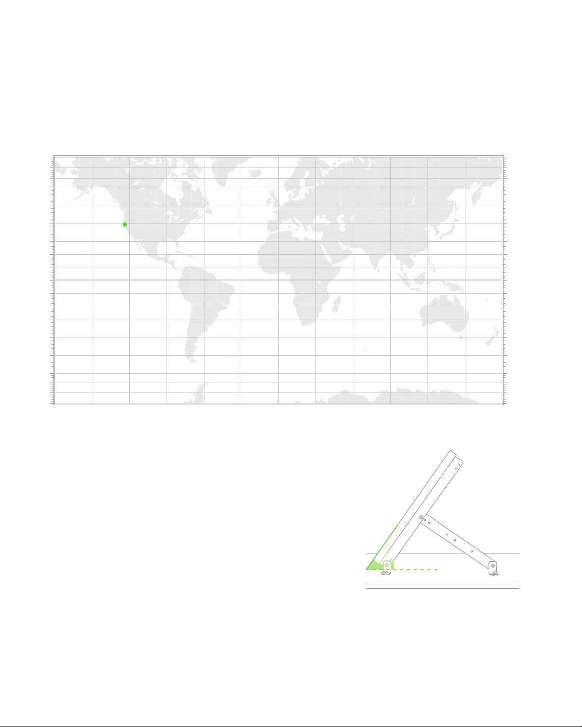
Elevation Angle
The elevation angle should point the panel directly at the sun at
noon during the winter. To determine the correct angle for your
location, find your location on the Elevation Angle Map above
and read off the elevation angle. The exact angle is not critical; a
variation of up to 5° is acceptable after the panel is installed.
Example: Let’s say you are in San Francisco, California. Look at
the map and find your location. According to the scale at the left
side of the map, your correct angle is 55°.
Use this space to record your elevation angle:
________________________ degrees
75°
45°
35°
25°
25°
35°
65°
85°
95°
105°
105°
95°
85°
55°
55°
65°
15°
45°
75°
75°
45°
35°
25°
25°
35°
65°
85°
95°
105°
105°
95°
85°
55°
55°
65°
15°
45°
75°
55 degrees
If you are within 1–2 degrees of latitude of the
equator, point the panel either north or south
(whichever direction has the lowest horizon)
at a 15 degree angle to assure that the panel
self-cleans when it rains.
8
On-Site Instructions
Checklist
The following tasks should be complete before you go on-site to complete your installation.
Solar repeater, solar panel, and Tools ready
solar panel mount ready
Mounting hardware ready Solar repeater configured on Dashboard
Orientation angle determined Elevation angle determined
Find a Good Mounting Location
A good mounting location is important to getting the best uptime and
repeater performance out of your Meraki Solar. Keep the following in mind:
1. The solar panel should have an unobstructed view of the sun from dawn till dusk, year round.
In addition, make sure that the unit will not cast a shadow onto the solar panel.
2. The solar repeater should have line of sight to at least 2, preferably 3 or 4, Meraki repeaters.
3. The solar repeater power cord is 15' (4.5 m) long, so the panel can be up to 15' from the repeater.
4. The antenna should be as unobstructed as possible. For example, do not place the unit
directry behind the solar panel.
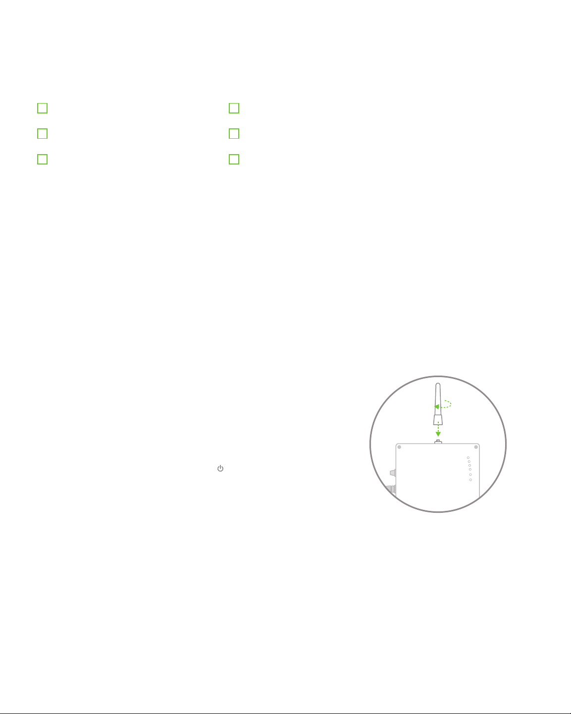
Pre-Installation Signal Strength Check
Before installing your Meraki Solar system, make sure your selected site
will give you good signal strength to your Meraki network.
Screw the antenna onto the solar repeater. Be careful not to over-tighten
the antenna; it only needs to be snug (do not use a wrench). Press the
power button on the side of the unit. The “ ” light on the front of the
unit should illuminate. If this does not happen, see the troubleshooting
section on page 20.
Use the signal strength LEDs to ensure that the unit has a strong
connection to your Meraki network. If the signal is weak, try repositioning
the unit. If the signal LEDs are alternating, then the unit is scanning and
cannot find a gateway. You will need to correct this before moving on.
Tip: If you want to see additional detail about other nearby Meraki devices, associate with the
Meraki Solar directly via wifi and go to http://setup.meraki.com. This page will give you
additional detail about the other devices that the Meraki Solar can see.

9
Install Solar Panel
There are several mounting options for your solar panel. You should have purchased either a pole
or a roof/wall mount kit. Follow the appropriate set of instructions below for your mount type.
Solar Panel Pole Mount Kit
x2
x2
Arm U-bracket Clamp
Hose Clamp 5/16" (8 mm)
Nut & Washer
5/16" (8 mm) in actual scale 1/4" (6.4 mm) in actual scale
1/4" (6.4 mm)
Nut & Washer
Spare hardware kit
x2
x2
x2
x4
x4
x4
x4
x8
10
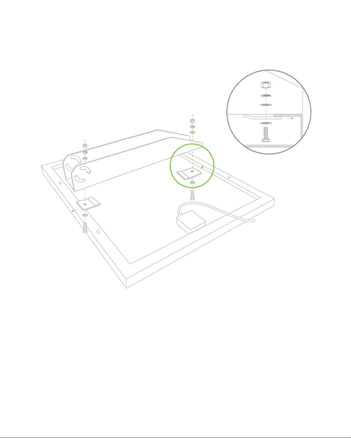
1. Attach the Mount Arm to the Solar Panel
Lay the solar panel face-down on a protected flat surface such as a towel or
carpet. Center the arm on the back of the panel and attach it to the panel as shown
using 1/4" (6.4 mm) bolts and clamps, gripping the edges of the panel frame be-
tween the arm and the clamps. Tighten the clamp nuts to 7 ft-lbs.
1
Pole Mount
Lock washer
Flat washer

11
2
2. Attach the U-bracket to the Pole Using Hose Clamps
Feed the hose clamps through the u-bracket. Tighten the hose clamp screws to 3 ft-lbs.
Note: Make sure the bracket is oriented correctly (determined in the “orientation” section on page 6) before
tightening screws.
Tip: Check the fit of the hose clamp to
your pole before installing. Trim off any
excess length of hose clamp with the
tin snips to save install time, leaving
about 2" (5.1 cm) of excess length
when installed.
Tip: Using an electric screwdriver with nut
driver will greatly reduce install time.
Tip: For a pole diameter greater than 4.5"
(11.4 cm), flip the bracket around so
the “u” faces the pole and flip it top-to-
bottom as seen in the above image.
Pole Mount
Top of pole
Top of pole

12
3. Attach the Panel and Arm to the U-bracket
Insert a single bolt through the panel mount arm and the u-bracket. Hand tighten
the bolt. Next, insert the other three bolts and hand tighten.
4. Set Proper Elevation Angle of Panel
Using the included inclinometer, set your solar panel to the angle that you calculat-
ed in the “Elevation” section on page 7. Tighten the 5/16"(8 mm) nuts to 12 ft-lbs.
3
4
Pole Mount
13
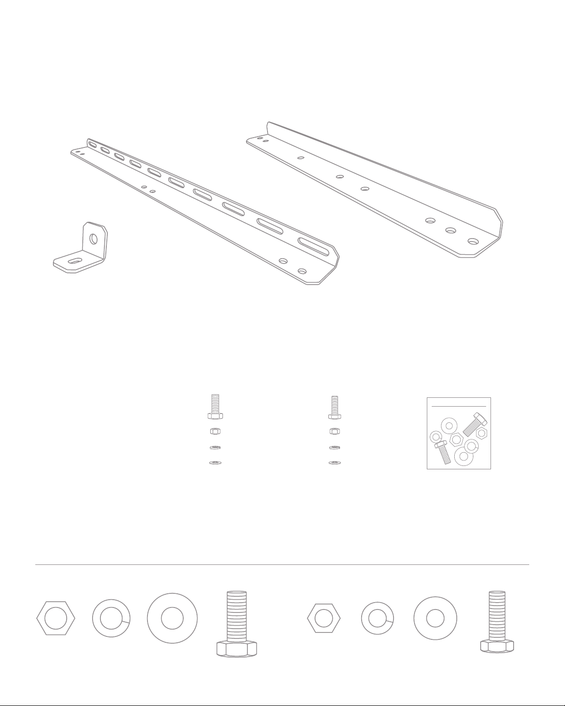
Solar Panel Roof or Wall Mount Kit
x4 x2 x2
Foot Rail Arm
5/16" (8 mm) in actual scale 1/4" (6.4 mm) in actual scale
5/16" (8 mm)
Nut & Washer
1/4" (6.4 mm)
Nut & Washer
Spare hardware kit
x4
x4
x4
x8
x6
x6
x6
x12

14
1. Attach the Rails to the Solar Panel
Lay the solar panel face-down on a protected flat surface such as a towel or carpet. Attach the rails
to the frame of the solar panel using 1/4" (6.4 mm) bolts. Put the bolts through the holes in the
frame and long slots on the rails. Tighten the nuts to 7 ft-lbs.
2. Attach the Arms to the Rails
Assemble the arms to the rails as shown using 5/16" (8 mm) bolts. Hand tighten nuts only.
3. Attach the Feet to the Arms and Rails
Assemble the feet to the arms and rails as shown using 5/16"(8 mm) bolts. Hand tighten nuts only.
Wall Mount
1
3
3
2
Lock washer
Flat washer
15
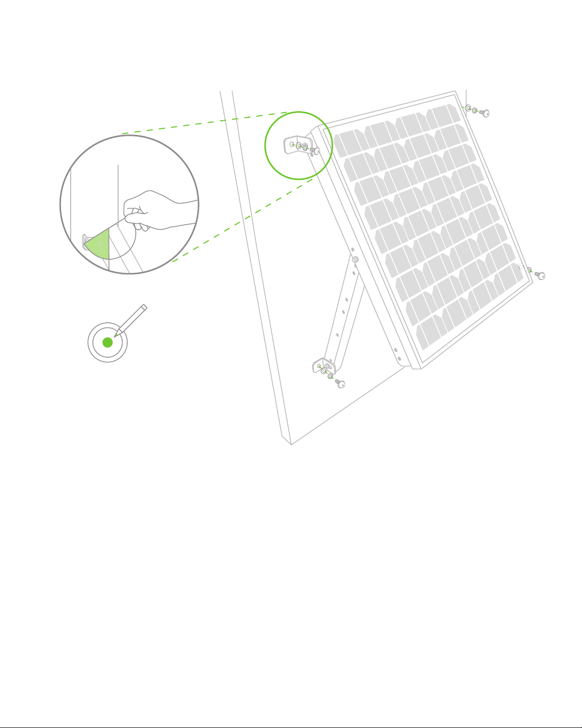
4. Attach Upper Feet to the Wall
Using appropriate wall anchors for the surface to which you are mounting the panel,
attach the upper feet to wall so that the panel hangs freely from these fasteners.
5. Set Proper Elevation Angle of Panel
Using the included inclinometer, set your solar panel to the angle that you calculated
in the “Elevation” section on page 7. See diagram for how to properly use the
inclinometer to set the angle of the panel.
Example: If you are in San Francisco, the correct elevation angle is 55 degrees.
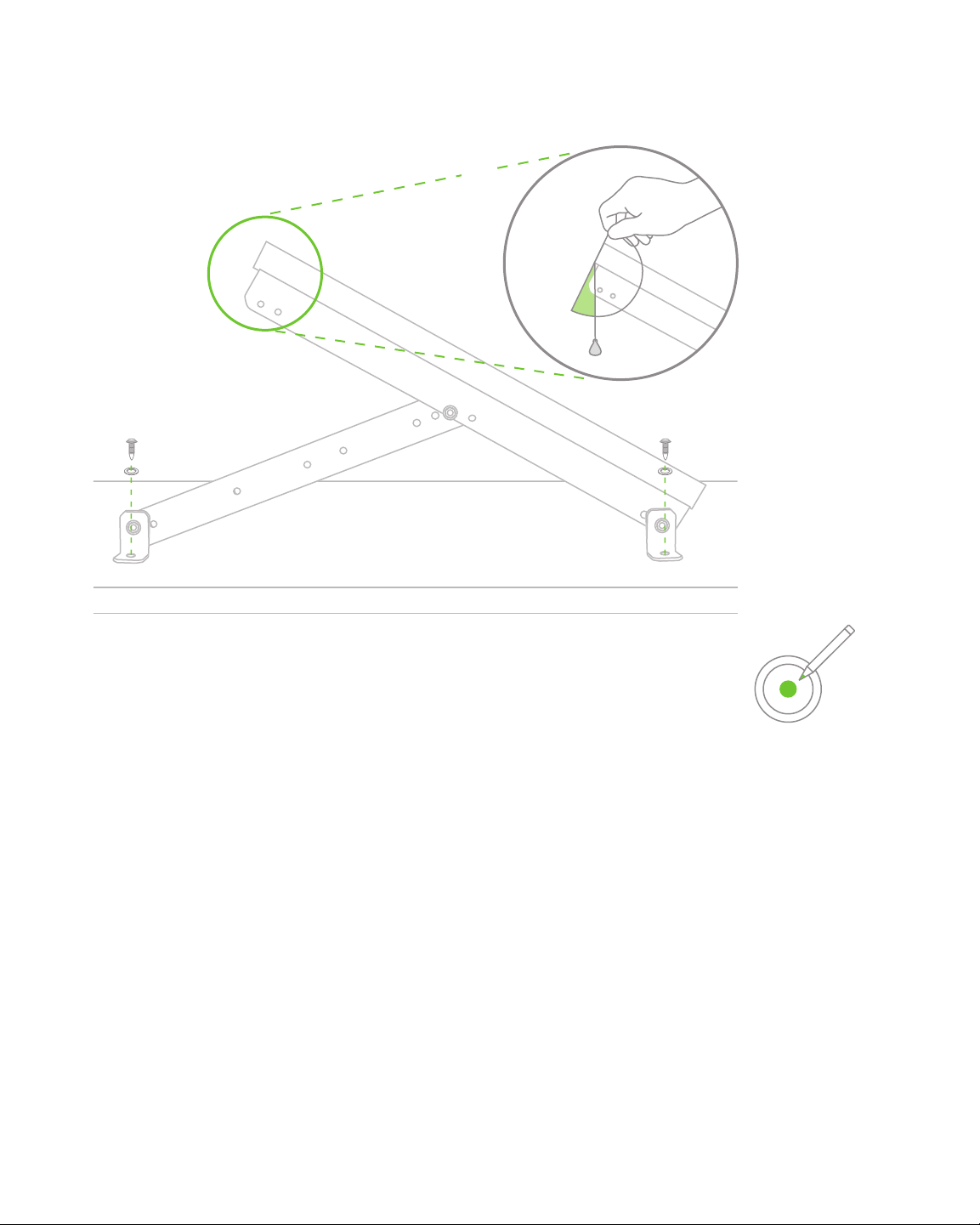
6. Attach Lower Feet to the Wall
Using appropriate wall anchors for the surface you are mounting the panel to, attach the
lower feet to wall in the correct locations. Tighten all 5/16"(8 mm) fasteners to 12 ft-lbs.
Wall Mount
4
6
5
Tip: Note where lower feet should
be attached to the wall to fix the
panel at the proper angle. Mark
the proper location of the feet on
the wall through the holes in the
feet using a pencil, pen or marker.

16
1. Attach the Rails to the Solar Panel
Lay the solar panel face-down on a protected flat surface such as a towel or carpet. Attach
the rails to the frame of the solar panel using 1/4" (6.4 mm) bolts. Put the bolts through the
holes in the frame and long slots on the rails. Tighten the nuts to 7 ft-lbs.
2. Attach the Arms to the Rails
Assemble the arms to the rails as shown using 5/16" (8 mm) bolts. Hand tighten nuts only.
3. Attach the Feet to the Arms and Rails
Assemble the feet to the rails as shown using 5/16" (8 mm) bolts. Hand tighten nuts only.
Roof Mount
The solar panel can be mounted to a flat or angled roof in the same
manner as to a wall. Confirm that your panel will be facing true south
(per “Orientation” section on page 6) within ±5 degrees once installed.
1
3
3
2
Lock washer
Flat washer
17
Roof Mount
4. Attach Upper Feet to the Roof
Using appropriate roof anchors for the surface you are mounting the panel to,
attach the upper feet to roof.
5. Set Proper Elevation Angle of Panel
Using the included inclinometer, set your solar panel to the angle that you
calculated in the “Elevation” section on page 7. Note where lower feet should
be attached to the roof to fix the panel at the proper angle.
6. Attach Lower Feet to the Wall
Using appropriate anchors for the surface you are mounting the panel to,
attach the lower feet to roof. Tighten all 5/16" (8 mm) fasteners to 12 ft-lbs.
4
6
Tip: Note where lower feet should
be attached to the roof to fix the
panel at the proper angle. Mark
the proper location of the feet on
the roof through the holes in the
feet using a pencil, pen or marker.
5

18
1. Attach Solar Repeater to the Pole
If using included u-bolts, tighten the nuts to 12 ft-lbs.
2. Attach the Solar Panel Cable to the Solar Repeater
Insert the plug and rotate the outer housing clockwise to lock it in place.
Mount the Solar Repeater
Your solar repeater can be mounted to a pole or wall. Remember, your solar repeater
can be up to 15' (4.5 m) away from your solar panel if using a Meraki solar panel.
Pole Mount
Your solar repeater includes 2.5" (6 cm) u-bolts for mounting to a 2.5" (6 cm) pole. If
you are mounting to a larger or smaller pole, you will need to use your own hardware.
1
2
Table of contents
Popular Solar Panel manuals by other brands

Hanwha Solar
Hanwha Solar HSL60P6-PB-1-xxx Series installation guide

NEO TOOLS
NEO TOOLS 90-141 user manual

Furrion
Furrion FSFP16MW3-BL user manual

Maxeon
Maxeon SunPower SPR-MAX5-415-E3-AC Safety and installation instructions

Schletter
Schletter PvMax3 Mounting instructions

GRIDFREE
GRIDFREE LIFESTYLE KIT installation manual


Viessmann
Viessmann Vitosol 200-T Service instructions

Sunforce
Sunforce 85 WATT MONOCRYSTALLINE SOLAR PANEL user manual

Waterboy
Waterboy MAXI ARRAY Installation

Trina Solar
Trina Solar Crystalline Series installation manual

Panasonic
Panasonic HIT VBHN330SA17 General installation manual

Pleion
Pleion EGO 150 Installation and user manual