Hanwha Solar HSL60P6-PB-1-xxx Series User manual

Installation
Guide
HSL Poly Series

2
DISCLAIMER OF LIABILITY
The installation techniques, handling and use of the product are beyond company control. Therefore, Hanwha Solar
assumes no responsibility for loss, damage or expense resulting from improper installation, handling or misuse.
Ensure that the module is used only in applications for which it is suitable (see “Mounting Instructions”). All work on a PV
system (installation, setup, maintenance) must be carried out only by appropriately qualified and authorized engineers.
The appropriate local standards, construction rules and safety instructions must be followed during installation.
INTRODUCTION
PURPOSE OF THIS GUIDE
SYSTEM DESIGN
MOUNTING INSTRUCTIONS
ELECTRICAL INSTALLATION
ADDITIONAL INFORMATION
3
3
4
5
8
10
CONTENT

Hanwha Solar is a leading manufacturer of silicon ingots,
wafers, PV cells and modules, delivering reliable products
at competitive pricing on a global scale. We provide
world-class PV technology, efficient manufacturing, and
local customer support. We are committed to providing
technical and installation support for our customers
worldwide. This Installation Guide covers installation of
the following Hanwha Solar modules:
This guide contains important information
regarding the installation, safe handling
and maintenance of photovoltaic modules
made by Hanwha Solar. The word “module”
as used in this guide refers to one or more
PV modules. All instructions should be
read and understood prior to installing the
modules. The installer should conform to all
the safety precautions in this guide when
installing the modules. Local standards and
regulations should also be followed during
installation. Before installing a photovoltaic
system, the installer must be familiar with
the mechanical and electrical requirements
for such a PV system. Keep this guide in
a safe place for future reference. Hanwha
Solar provides technical support worldwide.
Visit www.hanwha-solarone.com for
contact information.
UL Products
HSL60P6-PB-0-xxxT (W/B)
HSL60P6-PB-2-xxxQ (W/B)
HSL60P6-PB-3-xxxQ (W/B)
HSL60P6-PB-4-xxxT (W/B)
HSL72P6-PB-0-xxxT (W/B)
HSL72P6-PB-2-xxxQ (W/B)
HSL72P6-PB-3-xxxQ (W/B)
HSL72P6-PB-4-xxxT (W/B)
*xxx represents the power class
INTRODUCTION PURPOSE OF
THIS GUIDE
3
IEC Products
HSL60P6-PB-1-xxx (W/B)
HSL72P6-PB-1-xxx (W/B)

Before installing your solar system, contact local authorities to determine the necessary permit,
installation and inspection requirements that must be followed. System should be installed by
qualified personnel only. The system involves electricity, and can be dangerous if the personnel
are not familiar with the appropriate safety procedures. PV modules should be mounted in a
location where they will receive maximum sunlight throughout the year. Specially, in the northern
hemisphere, the modules should face south. And in the southern hemisphere, the modules should
face north.
SYSTEM DESIGN
• In order to achieve maximum annual yield, optimum orientation and tilt of PV module is necessary.
Sunlight shining vertically and completely onto PV module is the best condition to generate
maximum power.
• Artificially concentrated sunlight shall not be directed on the module. Very hot module(s) can
reduce power output performance. Ensure the module has good ventilation conditions to prevent
overheating.
• Site-specific environment loads such as wind and snow should be taken into account to avoid
exceeding the maximum load.
• When designing the system, please pay attention to the total voltage (if connected in series) and
current (if connected in parallel).
• You must not install more than three (3) modules in parallel without additional string fuses or string
diodes. While in series, the open circuit voltage of the string must not exceed the allowed maximum
system voltage (e.g. 1000Vdc for IEC certified systems), even under cold climate conditions.
• The module must not be installed close to fire or flammable materials. Completely cover the module
with an opaque material during installation to prevent electricity from being generated.
• Supplementary: If system grounding is required by system configuration or local authorities,
Hanwha SolarOne recommends negative system grounding which could have
positive effect on system performance.
4

MOUNTING INSTRUCTIONS
The basis for durable and safe mounting is an assembly frame which corresponds to the appropriate
structural requirements, which is securely anchored to the ground, to the roof, or to a façade, and
whose long-term stability is guaranteed. The mounting structure and the module attachments
must be designed in accordance with the local wind and snow loads. Ensure that the modules are
mounted over a fire resistant roof covering rated for the application. To prevent bending, vibration,
mechanical stress or warpage, mount the module onto a flat contact surface.
5
• Always secure the module with the correct number of clamps or screws or use appropriate mounting rails
• The distance between modules should be selected carefully respecting thermal expansions. In no
way modules should touch each other at any operating temperature to avoid unfavorable forces.
Keep in mind, different modules, mounting systems, and building materials do have different
thermal expansion coefficients. Hanwha Solar recommends a minimum distance of 20 mm between
modules
• Avoid direct contact between glass and metal (e.g. mounting rails)
• Modules can be installed in both landscape and portrait modes. Reduced snow loads may apply,
depending on mounting method
• For portrait installations, the junction box should be located in the upper area of the module and the
cables should hang downwards
• Recommended tightening torque: 10Nm for bolt mounting and clamp mounting unless otherwise
specified by mounting system provider
• Do not drill additional holes for installation (drilling holes shall void product warranty)
• Module clamps must not overlap the glass or shade the module surface
• The installation and attachment materials (nuts, bolts, etc.) must be corrosion-resistant
Bolt Mounting Details Clamp Mounting Details

IEC Products
6
Maximum Load/Pressure
4000 Pa
Bolt MountingClamping at the long module sidesClamping at the short module sides
Extended Maximum
Static Load 7000 Pa
140mm
250mm
140mm
250mm
Moun,ngholes
Moun,ngholes
Moun,ngholes
Moun,ngholes
140mm
250mm
140mm
250mm
Moun,ngholes
Moun,ngholes
Moun,ngholes
Moun,ngholes
ClampingArea
200mm
ClampingArea
200mm
MOUNTING INSTRUCTIONS
Clamping Area
90mm
350mm
Clamping Area
90mm
350mm
Clamping Area
440mm
Clamping Area
440mm
HSL60P6-PB-1-xxx (W/B)
HSL60P6-PB-0-xxxT (W/B)
HSL60P6-PB-2-xxxQ (W/B)
HSL60P6-PB-3-xxxQ (W/B)
HSL60P6-PB-4-xxxT (W/B)
UL Products

IEC Products
7
Maximum Load/Pressure
4000 Pa
Bolt MountingClamping at the long module sidesClamping at the short module sides
Extended Maximum
Static Load 7000 Pa
200mm
300mm
200mm
300mm
Moun*ngholes
Moun*ngholes
Moun*ngholes
Moun*ngholes
200mm
300mm
200mm
300mm
Moun*ngholes
Moun*ngholes
Moun*ngholes
Moun*ngholes
ClampingArea
550mm
ClampingArea
550mm
ClampingArea
150mm
400mm
ClampingArea
150mm
400mm
ClampingArea
200mm
ClampingArea
200mm
UL Products
HSL72P6-PB-0-xxxT (W/B)
HSL72P6-PB-2-xxxQ (W/B)
HSL72P6-PB-3-xxxQ (W/B)
HSL72P6-PB-4-xxxT (W/B)
HSL72P6-PB-1-xxx (W/B)

ELECTRICAL INSTALLATION
CORRECT WIRING SCHEME
To minimize the risk of an indirect lightning strike, avoid forming closed loops when designing the system. Check
that wiring is correct before starting the generator. If the measured open circuit voltage (Voc) and short-circuit
current (Isc) differ from the specifications, there may be a wiring fault.
SOLAR MODULE PLUG CONNECTORS
All solar modules are equipped with solar cables with 4-6mm² serving a temperature range from -40°C to 90°C.
The connectors have specified polarities; they are marked with ´+´ and ´-´ signs. Make sure that the connection is
safe and tight. Connectors should only be used to connect the circuit, but never used to turn the circuit on or off.
Connectors must not be exposed to direct rain or laid in water drains.
USE OF PROPER COMPONENTS
Use cable extensions and plugs that are designed for outdoor applications. Ensure that they are in good electrical
and mechanical condition. Only cables with one conductor are to be used. Ensure that all materials meet the
requirements of the systems` maximum voltage, current, moisture, and temperature when they are exposed to
sunlight. Under normal conditions, a photovoltaic module is likely to produce more current and/or voltage than
that reported under Standard Test Conditions. Accordingly, the values of Isc and Voc marked on the module should
be multiplied by a factor of 1.25 when selecting electrical components voltage ratings, conductor capacities, fuse
type, and type of control components connected to the PV output.
The maximum series fuse rating is:
•10A for modules with Hanwha Solar 125x125mm cells
•15A for modules with Hanwha Solar 156x156mm cells
The maximum reverse current is known as series fuse rating multiplied by a factor of 1.35. Each module (or series
string of modules so connected) shall be provided with the maximum series fuse as specified.
For USA:
Refer to Section 690-8 of the U.S. National Electrical Code for an additional multiplying factor of 1.25 which may
be applicable.
BYPASS DIODES
When modules in series are partially shaded, it may cause reverse voltage across cells or modules, this may cause
undesirable heating to occur. The use of a diode to bypass the shaded area can minimize both heating and array
current reduction. All Hanwha Solar modules are equipped with factory installed bypass diodes. The factory
installed diodes provide proper circuit protection for the system.
OTHERS
During installation, be sure to tie the cable from the junction box to the mounting substructure with nylon line, etc.
to avoid direct contact of the cable with the back surface of the module.
8

GROUNDING
The frame shall be grounded in accordance with local electrical requirements*. If grounding of the modules is
required, a good connection between modules and the grounding hardware is essential for an effective ground. The
anodization on a module frame provides a coating to minimize the corrosion due to weather and it acts as a barrier
that reduces the effectiveness of the grounding connection. For an adequate electrical connection, the grounding
hardware should penetrate the anodized layer.
9
* For UL Products: Only UL listed equipment should be used for bonding to ground. For USA: National electrical code (NEC) Article 250; for Canada: CEC
Aluminum frame
Grounding mark
Grounding holes
2-ø4.5
1 Stainless steel bolt M4 × 30 2 Stainless steel nut M4 3 Stainless steel flat washer M4
4 Stainless steel spring washer M4 5 Stainless steel lock-toothed washer M4 6 Stainless steel slotted washer M4
1
2
4
3
5
6
Option 1: Bolting ground Option 2: Grounding lug with machine screw at frame hole
Select a grounding lug listed for direct burial and outdoor use
(tin-plated, solid copper lay-in lug with a stainless-steel set
screw) capable of accepting a 4-14 AWG copper conductor.
Secure the lug to module grounding hole with a stainless
steel machine screw, flat washer, serrated washer and nut.
Tighten the nut to approximately 2.26 N-m (20 in-lbs).
Tighten the lug set screw to the copper wire at the torque
specified by lug manufacturer.
Nut
Serrated washer
Module frame
Lay-in lug
Flat washer
Machine screw
In case grounding is required, Hanwha Solar recommends using the follow components or equivalents.
IEC/EN61730 INFORMATION
Hanwha Solar module is designed to fulfill the criteria of Application Class A requirements according to IEC/EN61730-
part1. The modules are qualified for application class A: Hazardous voltage (IEC61730: higher than 50V DC; EN61730:
higher than 120V), hazardous power applications (higher than 240W) where general contact access is anticipated
(Modules qualified for safety through EN IEC61730-1 and EN IEC61730-2 within this application class are considered
to meet the requirements for Safety Class II.
UL LISTING INFORMATION
1. Rated electrical characteristics are within 10% of measured values at Standard Test Conditions of:
1000W/ m², 25°C cell temperature and solar spectral irradiance per ASTM E892 or irradiance of AM 1.5
spectrum.
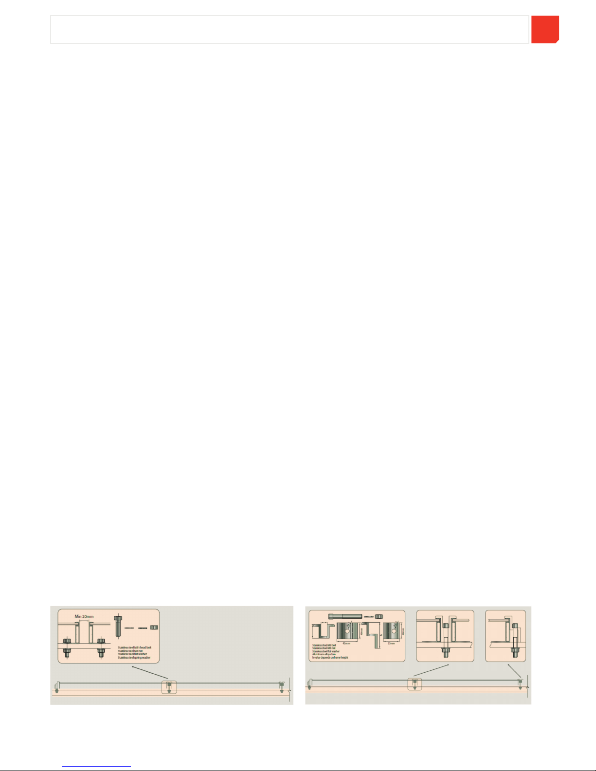
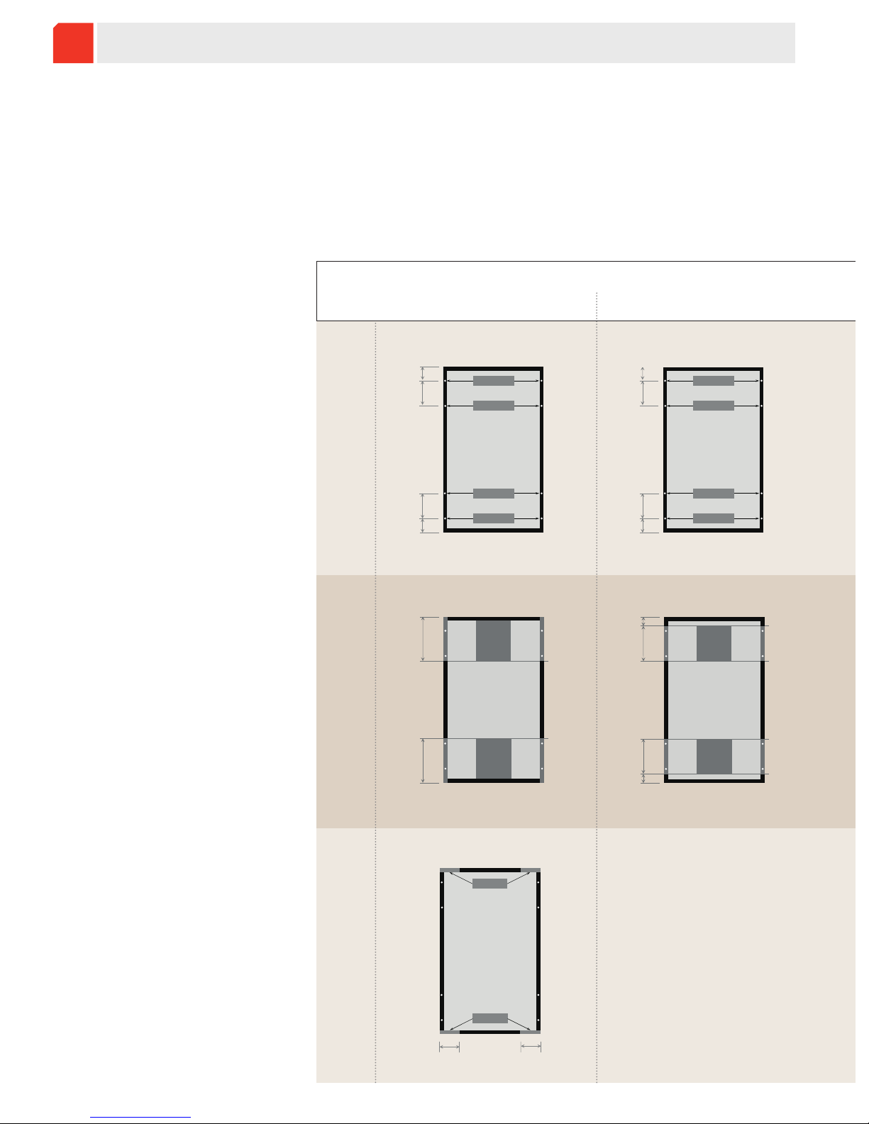
2. The standoff height should be at least 7.9 in. If other mounting means are employed, this may affect the
UL Listing.
3. The modules have been evaluated by UL for a maximum positive or negative design loading of 30 lbs/ft².
4. Wiring methods should be in accordance with the NEC.
5. For installations in Canada, the installation shall also be in accordance with CSA C22.1, safety Standards
for Electrical Installations, Canadian Electrical Code, Part 1.
6. The use of the following hardware is required in order to provide a reliable grounding connection to the
module frame: a combination of the following stainless steel hardware: Serrated washer, Spring washer,
flat washer, a size M4 nut, and bolt M4x30mm -- (see illustration grounding for details).

ADDITIONAL INFORMATION
10
WARNING!
PV modules generate electricity as soon as they are exposed to sunlight. One module generates a safe, extra-
low voltage level, but multiple modules connected in series (summing the voltage) or in parallel (summing
the current), represent a danger. The following points must be noted when handling the solar modules to
avoid the risk of fire, sparking, and fatal electric shock.
UNPACKING AND STORING MODULES
Utmost attention is required when handling module(s). The following guidelines should be followed with
caution while unpacking, transporting, and storing the modules:
Do not insert any electrically conductive materials into the plugs or sockets.
Do not fit PV modules and wiring with wet plugs and sockets.
Make sure to use proper safety equipment (insulating tools and gloves, etc.) when wiring.
Make sure that the connection is made when the circuit is cut off.
Do not disconnect under load.
To avoid the generation of an electric arc, ensure the connectors are clean and have not been
contaminated,and that the electrical connection and mechanical joint are good.
Open the packaging with care, especially when handling sharp blades. Lift the modules out of
carton box with two or more persons.
Do not strike or physically damage the module.
Carry modules with proper method in order to avoid module breakage. Using both hands is
recommended. Do not use the junction box or the cables as a handle.
Place the module with proper support. Do not place modules on top of each other. Do not twist
the module.
Do not stand on the module.
Do not mark the rear of the module using sharp objects.

ADDITIONAL INFORMATION
11
NORMAL OPERATING CONDITIONS FOR HANWHA SOLAR MODULES
Operating conditions
• The operating temperature of PV module should be within -40°C to 85°C (-40°F to 185°F).
• Ensure adequate ventilation behind the module, especially in hot environments.
• Module should be installed at least 500m from the sea to avoid corrosion due to exposure to salt.
• Other sources of corrosion, including sulfur (from sulfur sources such as volcanoes), can also lead to
performance degradation and should be avoided.
Location conditions
The following location conditions should be avoided when installing a module:
• Location with potential for extreme sand and dust damage.
• Location with extreme air pollution, chemical vapors, acid rain, and/or soot, etc.
• Location with extreme hail and/or snow.
• Location with potential extreme salt damage.
MAINTENANCE AND CARE
Dirt on the surface of the solar module may decrease power generation. Keep module surface free from any
dirt which potentially shades the cells. An at least 10 degree inclination supports the self-cleaning function
of the glass. If you still need to clean the module or if soiling on the module glass becomes excessive, use a
soft cloth and water for cleaning.
CAUTION: DO NOT USE ABRASIVE DETERGENTS
Please consult with system designer to decide the cleaning frequency according to local environmental
conditions. Once a year, check the electrical and mechanical devices to ensure every connection is tight.
The system must be periodically inspected.

CERTIFICATIONS
International Product Safety Certifications
TÜV, CE, UL, and Safety Class II certifications ensure that Hanwha Solar’s
products operate safely and comply with electrical and fire safety codes
around the world.
International Product Performance Certifications
IEC Certification ensures our products’performance and reliability.
International Quality Manufacturing Certifications
ISO 9001, OHSAS 18001, and TÜV factory inspections confirm that
Hanwha Solar’s manufacturing is carried out under proven quality
control and manufacturing processes.
Environmentally Responsible Manufacturing
ISO 14001 Certification and PV Cycle membership ensures that Hanwha
SolarOne’s manufacturing is performed with respect for the environment.
www.hanwha-solarone.com
INTERNATIONAL OFFICES
Hanwha SolarOne Co., Ltd.
No. 888, Linyang Road, Qidong
Jiangsu Province, 226200, China
Phone: 86-513-8360-6222
Fax: 86-513-8360-6278
Hanwha SolarOne GmbH
Headquarter Sales EA-Germany
Oskar Messter Straße 13
85737 Ismaning, Germany
Tel: 49-89-2175-667-30
Fax: 49-89-2175-667-399
Representative Office-Italy
Via Santa Maria Valle 3
20123 Milan, Italy
Tel: 39-02-00681-281
Fax: 39 02 00681-400
Representative Office-France
21 Avenue Le Corbusier
59042 Lille cedex, France
Tel: 33-359-811-751
Fax: 49-89-2175-667-399
Representative Office-Spain
Notari Badia, n4-Local 11
08221 Terrassa, Barcelona, Spain
Tel: 34-931-93-97-63
Fax: 34-901-70-66-22
Hanwha SolarOne USA
2424 Walsh Avenue,
Santa Clara, CA 95051
8001 Irvine Center Drive, Suite 1250
Irvine, CA 92618
Tel: 1-714-689-6868
Fax: 1-714-689-6868
For more information, and to contact
local sales or after-sales technical support,
please visit our website at:
www.hanwha-solarone.com
©Hanwha SolarOne Co., Ltd. Specifications are subject to change without notice.
Release: 2013-04-10 HW3.819.183SCV1
This manual suits for next models
9
Table of contents
Other Hanwha Solar Solar Panel manuals
Popular Solar Panel manuals by other brands

Renogy
Renogy 100W Solar Suitcase manual

Hali-Brite
Hali-Brite SPS Series Installation and maintenance manual

EDN
EDN RADIASOL 150 D Instructions for installation, use and maintenance manual

Viessmann
Viessmann Vitosol 300-T installation instructions

PVP
PVP PVP-A Series General installation manual

Simplicity
Simplicity 5600352 Operator's manual

King Pigeon
King Pigeon SLP1210-P instruction manual

AU Optronics
AU Optronics BenQ PM096BW0 installation guide

FREEFORCE
FREEFORCE ULTRALITE 600 user manual

Wolf
Wolf CFK-1 Installation, operating and maintenance instructions

SolarGo2
SolarGo2 FP110-PWM user manual

Navitron
Navitron SFB Series installation manual