Mercura GYROLED M130 ISO BASE SB1 User manual

20/02/2017
GYROLED® M130 ISO BASE SB1
GT-0657-FEUX Ind C
Head-quarters : Zone d’Activités « Les Gailletrous » - 4 rue Louis Pasteur- 41260 LA CHAUSSEE SAINT VICTOR - France
Tel : 00 33 (0) 2 54 57 52 52 –Fax 00 33 (0) 2 54 56 80 00
SAS au capital de 102. 400 € - APE (NAF) 2790 Z –SIRET 310 999 891 00040
Page 1
30161-02
1. GYROLED® M130 –Reference according to colour
2. PROTECTIVE SEAL - Reference 29637
3. USER MANUAL - Reference 29816
4. STAINLESS STEEL SCREW H M06x16 (x3) & FLAT WASHER (x3)
5. GYROLED M130 WIRING LOOM (x1) –Reference 30024
6. MINIFIT MOLEX PINS (x4) –Reference 25530
7. NYLON BAG –Reference 16782
MERCURA’s GYROLED® M130 SB1 is a high power CLASS 2 LED beacon. The light is
supplied with 14 integrated flash patterns.
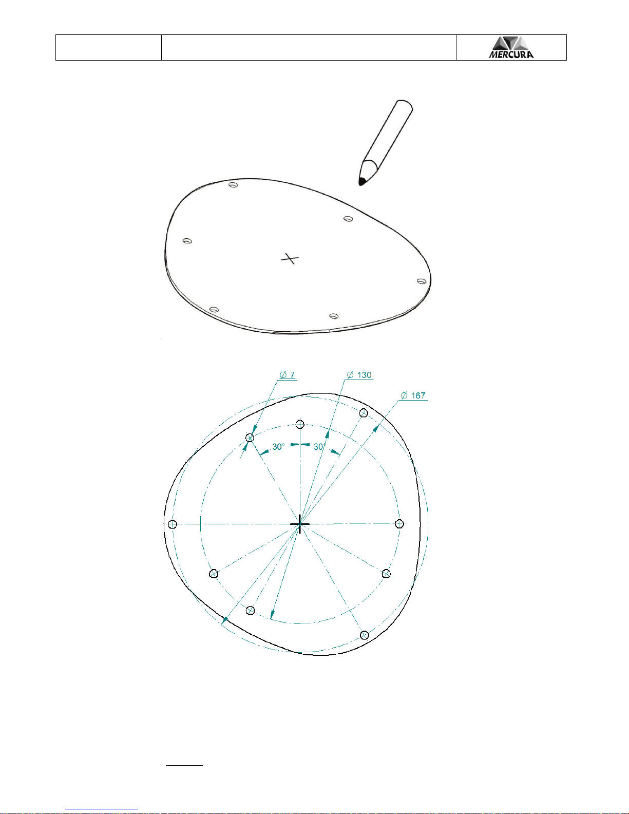
Two fixing diameters are available: 1 x ISO type Ø130 and 1 x 3-point fixing mode Ø167.
The M130 is supplied with a 10-pin connector and a wiring loom with 4 pre-connected
wires. A pin set is also supplied to add secondary functions (Synchronisation etc…)
The M130 is also delivered with a protective rubber seal that ensures the interface with the
vehicle roof.
The GYROLED® M130 is available in the following colours:
Blue
Amber
Red
Green
White
Power supply : 10 –30 Volts
Weight : 1,274 Kg
Low voltage cut off value : 8 volts
All available Flash patterns :
1. Rotating R65
2. Double Flash R65
3. Triple Flash
4. Single Flash
5. ½ Rotating
6. ½ Double Flash
7. ½ Triple Flash
8. ½ Single Flash
9. ICAO Flash
10. ICAO Rotating
11. ½ ICAO Flash
12. ½ ICAO Rotating
13 Double Flash R65 (Day) / Rotating R65 (Night)
14. Top central LED on only
The GYROLED® M130 is R65 approved in Blue, Amber and Red colour only
Power : 22W max.
Operating temperature :
-40°C to +85°C
References GYROLED® ISO:
Blue : 28700 Blue SB1 : 29812
Amber : 28701
Red : 28703
White : 28702
Green : 28704
R65 approval
Blue Flash : TB2 E2 0016105
Blue Rotating : TB2 E2 0016106
Amber Flash : TA2 E2 0016107
Amber Rotating : TA2 E2 0016108
Red Flash : TR2 E2 0016220
Red Rotating : TR2 E2 0016221
"E" Marking Approval R10 n° « E2 10R05 16034 »
CISPR25 (2008) : class 4 or 5 radiating
20/09/2017
GYROLED® M130 ISO BASE SB1
GT-0657-FEUX Ind B
Head-quarters : Zone d’Activités « Les Gailletrous » - rue Louis Pasteur- 41260 LA CHAUSSEE SAINT VICTOR - France
Tel : 00 33 (0) 2 54 57 52 52 –Fax 00 33 (0) 2 54 56 80 00
SAS au capital de 102. 400 € - APE (NAF) 2790 Z –SIRET 310 999 891 00040
Page 2
30161-01
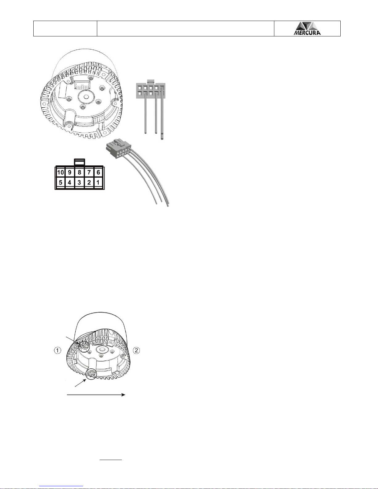
Pin n°1 : Wire n°1 : Ground power supply GYROLED M130
Pin n°2 : Wire n°2 : NIGHT function
Pin n°3 : REAR HALF FLASH function
Pin n°4 : Wire n°4 : Operating mode selection
Pin n°6 : Wire n°6 : « + » power supply GYROLED M130
Pin n°7 : Synchronized Input mode n°1
Pin n°8 : Synchronized Input mode n°2
Pin n°9 : Output synchronisation
The GYROLED® M130 is supplied with a connector kit including 4
silk-printed wires. 4 pin Molex Minifit unwired. The connector is
equipped with the 4 basic operating wires (Power supply "+" and "-"
Selection Mode, Night Gyroled®), the other pins provided separately
correspond to the connector pin numbers and are associated with
operating options (synchronization).
To select an operating mode from among the 14 available, power the
Gyroled® M130 then apply pulses to "+ Battery" to wire n°4 until you reach
the required pattern. The selected pattern remains in the memory even if
the Gyroled® M130 has been disconnected.
Note : To enable easy identification of the flash patterns, the14th mode is
only has the central LED lit up at the top of the beacon.
The NIGHT function reduces the beacon light brightness during a night
Intervention except 13th pattern (Flash to rotate mode).
The REAR HALF FLASH function lights up 8 of the 13 leds to the rear.
The choice of the Gyroled® M130 position on a roof vehicle must meet regulation requirements on light signalling installation.
The Gyroled® M130 should be placed vertically, so that the light beam is projected onto a horizontal plane.
It is also very important to adhere to certain rules of proximity to other equipment. Therefore, the Gyroled® M130 must be mounted
at more than 30 centimeters away from radio or telephone equipment (transceiver, cables, antennas, filters).
It is crucial to follow recommendations about electrical wire dimensions (diameter and length) in order to maintain the efficiency of
the line protection (fuse). Also we recommend the use of 1mm² section wire for the power supply.
The protective fuse must be positioned head-on closest to the battery. Its value must take into account the consumption of the
equipment installed, as well as the length of the line itself (2A at 12 volts ; 1A at 24 volts).
The Gyroled® M130 connections must be crimped using the appropriate tools.
GYROLED® M130 POSITIONING
MOUNTING INDICATIONS
The GYROLED® M130 installation on the vehicle roof must be done in a
specific way. The 2 small ducts on the base must be placed to the rear.
1. Rear
2. Front
20/09/2017
GYROLED® M130 ISO BASE SB1
GT-0657-FEUX Ind B
Head-quarters : Zone d’Activités « Les Gailletrous » - rue Louis Pasteur- 41260 LA CHAUSSEE SAINT VICTOR - France
Tel : 00 33 (0) 2 54 57 52 52 –Fax 00 33 (0) 2 54 56 80 00
SAS au capital de 102. 400 € - APE (NAF) 2790 Z –SIRET 310 999 891 00040
Page 3
30161-01
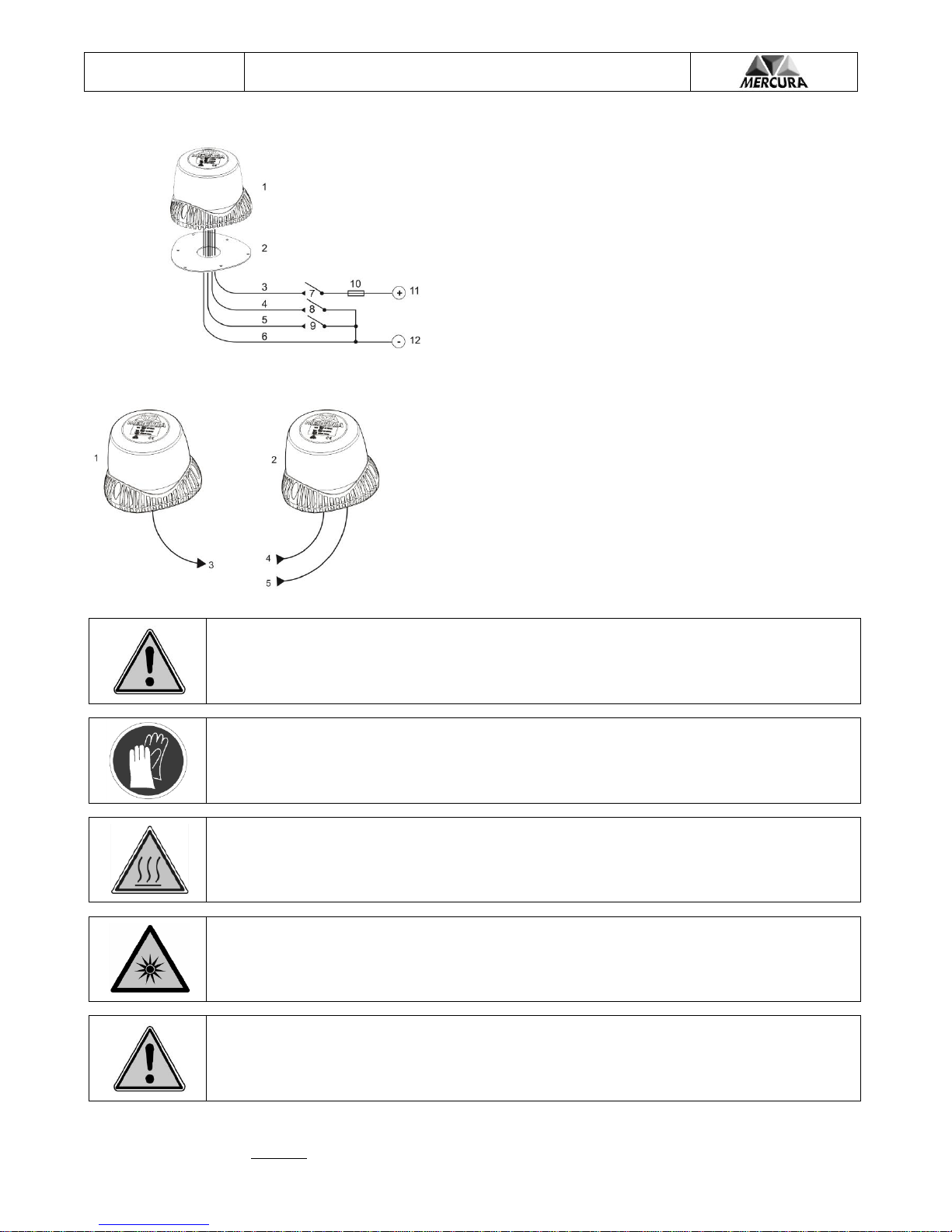
CONNECTING THE POWER SUPPLY, CRUISE FUNCTION, NIGHT FUNCTION
1. GYROLED® M130
2. Protective seal GYROLED M130 / Roof vehicle
3. Wire n°6 power supply GYROLED M130
4. Wire n°2 : Night function
5. Wire n°3 : REAR HALF FLASH function
6. Wire n°1 : Ground power supply GYROLED M130
7. M130 GYROLED® control (not supplied)*
8. Night function control (not supplied)
9. Cruise function control (not supplied)
10. Power line fuse (not supplied)
11. « + » Battery
12. Ground Battery
(*) ATTENTION ! « + » Battery M130 GYROLED® control
only.
CONNECTING THE SYNCHRONISATION MODE
1. GYROLED® M130 « Master »
2. GYROLED® M130 « Slave »
3. Wire n°9: Synchronisation signal output
4. Wire n°7 : Synchronisation signal n°1 input (Synchronisation in phase)
5. Wire n°8 : Synchronisation signal n°2 input (Synchronisation in phase
opposition)
The synchronization between 2 GYROLED® M130 is done by connecting
the "Master" beacon wire n°9 "Synch. output " to one of the 2 "Slave" beacon
synch. inputs according to the synch. mode chosen.
The Gyroled M130 installation on the vehicle should be done in compliance with the specific current
regulations regarding emergency and service vehicles special lighting. The beacon flash pattern choice must
also meet these requirements.
The installer is therefore fully responsible for the product installation and flash pattern chosen.
Handle the GYROLED M130 with precaution. Wearing gloves is recommended to avoid cuts and scratches on
the hands during installation.
Do not handle the GYROLED® M130 immediately after use, to avoid burning the hands, as the aluminum
base may still be hot.
Do not stare directly at the GYROLED during operation, so as to avoid eye damage.
The wiring loom passage from the Gyroled through to the vehicle interior must be absolutely waterproof.
The use of an impermeable seal is recommended.
20/09/2017
GYROLED® M130 ISO BASE SB1
GT-0657-FEUX Ind B
Head-quarters : Zone d’Activités « Les Gailletrous » - rue Louis Pasteur- 41260 LA CHAUSSEE SAINT VICTOR - France
Tel : 00 33 (0) 2 54 57 52 52 –Fax 00 33 (0) 2 54 56 80 00
SAS au capital de 102. 400 € - APE (NAF) 2790 Z –SIRET 310 999 891 00040
Page 4
30161-01
Table of contents
Other Mercura Automobile Accessories manuals


Popular Automobile Accessories manuals by other brands

Ridewell Suspensions
Ridewell Suspensions RAR-240 owner's manual

Prime Design
Prime Design FBM-1026-BLK Assembly instructions

ViseeO
ViseeO MB-2 user manual

Briggs & Stratton
Briggs & Stratton IS4500Z Series installation instructions

SilverCloud
SilverCloud Easy Drive 12 Instructions for use

Ameristar
Ameristar S6 quick start guide

Fiamma
Fiamma 02093A05A Installation and usage instructions

Bowers & Wilkins
Bowers & Wilkins Turnoverball 1020 installation instructions

Curt Group
Curt Group ARIES S225045 installation manual

AMP Research
AMP Research PowerStep 75124-01 installation guide

Menabo
Menabo PROFESSIONAL Fitting instructions

Cruz
Cruz N+ Series Assembly instructions


