Mercura VEGA LIGHTBAR CLASS 2 Series Quick start guide

General Technical Guide VEGA Lightbars Class 2 Siren / SPA Handy with Roof Connector
GT-0775-RAM Ind B
24/10/2018
Head Office: Zone d’Activités « Les Gailletrous » - rue Louis Pasteur- 41260 LA CHAUSSEE SAINT VICTOR
Tel : 02 54 57 52 52 –Fax 02 54 56 80 00
SAS with capital 102. 400 € - APE (NAF) 2790 Z –SIRET 310 999 891 00040
Page 1
31946-01
GENERAL TECHNICAL GUIDE
VEGA LIGHTBARS CLASS 2 SIREN / SPA HANDY
WITH ROOF CONNECTOR
1. KIT COMPOSITION..................................................................................................................................................2
2. AVAILABLE VERSIONS ...........................................................................................................................................3
3. DIMENSIONS............................................................................................................................................................3
4. WEIGHT DEPENDING ON VERSIONS ...................................................................................................................3
5. ELECTRICAL CHARACTERISTICS.........................................................................................................................4
6. INSTALLATION.........................................................................................................................................................5
6.1. SYNOPTIC........................................................................................................................................................5
6.2. INSTALLATION OF MOUNTINGS....................................................................................................................5
6.3. 18-POINT ROOF CONNECTOR ......................................................................................................................6
6.4. ROOF MOUNTING ...........................................................................................................................................6
6.5. BASE DIMENSIONS.........................................................................................................................................6
6.6. ROOF DRILLING DIAGRAM ............................................................................................................................7
6.7. MOUNTING EVALUATION...............................................................................................................................7
6.8. LIGHTBAR INSTALLATION............................................................................................................................10
7. GENERAL WIRING DIAGRAM (DEPENDING ON MODEL) .................................................................................11
7.1. WIRING SYNOPTIC........................................................................................................................................11
7.2. VEHICLE’S HARNESS GENERAL WIRING DIAGRAM.................................................................................12
7.3. HANDBRAKE MODULE OPTION...................................................................................................................13
7.4. DASHBOARD INTERFACE OPTION.............................................................................................................13

General Technical Guide VEGA Lightbars Class 2 Siren / SPA Handy with Roof Connector
GT-0775-RAM Ind B
24/10/2018
Head Office: Zone d’Activités « Les Gailletrous » - rue Louis Pasteur- 41260 LA CHAUSSEE SAINT VICTOR
Tel : 02 54 57 52 52 –Fax 02 54 56 80 00
SAS with capital 102. 400 € - APE (NAF) 2790 Z –SIRET 310 999 891 00040
Page 2
31946-01
1. KIT COMPOSITION
A. VEGA lightbar with siren equipped with wiring harness (see available versions §2)
B. Vehicle’s harness with 18-point roof connector
C. BUS-wired adaptor kit
D. Adjustable mountings
Options
C. SPA Handy control box
D. Multiplexed control box
E. Dashboard Interface
F. CCS BLL module for traditional controls (via switches)
G. Hand brake module (For controls depending on the condition of the hand brake: grill lights, flashing
scrolling...)
WARNING CONCERNING THE MOUNTING OF MERCURA’S EQUIPMENT
The installer is fully responsible for the mounting of equipment on a vehicle.
The installer must define the means and the material necessary for mounting of equipment in order to deliver the
vehicle equipped according to the regulations.
MERCURA is not responsible for failures occurring due to incorrect definition of the type of mounting system,
reinforcements, drilling holes in roof panel, state and quality of mounting system, use of vehicle manufacturer
anchoring points and the system power supply and protection definition in accordance with the vehicle energy
source.

General Technical Guide VEGA Lightbars Class 2 Siren / SPA Handy with Roof Connector
GT-0775-RAM Ind B
24/10/2018
Head Office: Zone d’Activités « Les Gailletrous » - rue Louis Pasteur- 41260 LA CHAUSSEE SAINT VICTOR
Tel : 02 54 57 52 52 –Fax 02 54 56 80 00
SAS with capital 102. 400 € - APE (NAF) 2790 Z –SIRET 310 999 891 00040
Page 3
31946-01
2. AVAILABLE VERSIONS
Length
Side
Front
Rear
Alley lights
Reference
1200
Blue
Blue
x
x
29243
1600
29245
1200
Blue
Blue
Blue
x
29247
1600
29249
1200
Blue
Blue
Amber
Yes
29251
1600
x
29253
1200
Amber
Amber
Amber
x
29255
1600
x
29257
1200 SPA
Blue
Blue
Amber
Yes
29260
1300 SPA
Amber
Amber
Amber
29261
3. DIMENSIONS
4. WEIGHT DEPENDING ON VERSIONS
REFERENCES
29239
29241
29243
29245
29247
29249
29251
29253
29254
29257
12 kg
13.5 kg
12.5 kg
14 kg
13 kg
14.5 kg
13 kg
14.5 kg
13 kg
14.5 kg

General Technical Guide VEGA Lightbars Class 2 Siren / SPA Handy with Roof Connector
GT-0775-RAM Ind B
24/10/2018
Head Office: Zone d’Activités « Les Gailletrous » - rue Louis Pasteur- 41260 LA CHAUSSEE SAINT VICTOR
Tel : 02 54 57 52 52 –Fax 02 54 56 80 00
SAS with capital 102. 400 € - APE (NAF) 2790 Z –SIRET 310 999 891 00040
Page 4
31946-01
5. ELECTRICAL CHARACTERISTICS
Operating voltage: 10.5-30 Volts
CONSUMPTION (1.20 m & 1.60 m LIGHTBARS)
The 1.20 m and 1.60 m lightbars of identical configurations have the same number of lights.
Blue Lights
Flash R65 function
6.3 A peak for 13.5 volts / 3.2 A peak for 27 volts
2.2 A average for 13.5 volts / 1.3 A average for 27 volts
Alley lights left and right: 1 A for 13.5 volts
Amber Warning Lights
Flash Mode
2.1 A peak for 13.5 volts / 1.3 A peak for 27 volts
1.1 A average for 13.5 volts / 0.7 A average for 27 volts
Left Scrolling Mode
0.6 A peak for 13.5 volts / 0.4 A peak for 27 volts
0.35 A average for 13.5 volts / 0.25 A average for 27 volts
Right Scrolling Mode
0.6 A peak for 13.5 volts / 0.4 A peak for 27 volts
0.35 A average for 13.5 volts / 0.25 A average for 27 volts
Flash set with alley lights and amber warning bar in flashing mode
9.8 A peak for 13.5 volts / 5 A peak for 27 volts
4.3 A average for 13.5 volts / 2.3 A average for 27 volts
Siren
4.2 A for 13.5 volts
2.1 A for 27 volts
Examples of fuse values* (*not supplied)
VEGA lightbars with siren, front and rear lights with or without alley lights:
30 A for 12 volts
15 A for 24 volts
VEGA lightbars with siren and only front lights:
20 A for 12 volts
10 A for 24 volts
VEGA lightbars with siren and without front or rear lights:
20 A for 12 volts
10 A for 24 volts

General Technical Guide VEGA Lightbars Class 2 Siren / SPA Handy with Roof Connector
GT-0775-RAM Ind B
24/10/2018
Head Office: Zone d’Activités « Les Gailletrous » - rue Louis Pasteur- 41260 LA CHAUSSEE SAINT VICTOR
Tel : 02 54 57 52 52 –Fax 02 54 56 80 00
SAS with capital 102. 400 € - APE (NAF) 2790 Z –SIRET 310 999 891 00040
Page 5
31946-01
6. INSTALLATION
6.1. SYNOPTIC
6.2. INSTALLATION OF MOUNTINGS
Assembly of upper and lower mountings
8 x CHC M06x12 INOX screws
16 x Ø6x14x1.2 IN A4 flat washers
8 x H M06 IN A4 locking nuts
Installation of mountings on base
4 x H M06x20 IN screws
4 x Ø6x14x1.2 IN A4 flat washers
4 x H M06 IN A4 locking nuts

General Technical Guide VEGA Lightbars Class 2 Siren / SPA Handy with Roof Connector
GT-0775-RAM Ind B
24/10/2018
Head Office: Zone d’Activités « Les Gailletrous » - rue Louis Pasteur- 41260 LA CHAUSSEE SAINT VICTOR
Tel : 02 54 57 52 52 –Fax 02 54 56 80 00
SAS with capital 102. 400 € - APE (NAF) 2790 Z –SIRET 310 999 891 00040
Page 6
31946-01
6.3. 18-POINT ROOF CONNECTOR
A. Roof connector base
B. Protective cap of the roof connector
C. Roof connector gasket
6.4. ROOF MOUNTING
A. Vehicle’s roof
B. Vehicle’s 2 drilling points
C. Roof connector gasket
D. 18-point roof connector base
6.5. BASE DIMENSIONS

General Technical Guide VEGA Lightbars Class 2 Siren / SPA Handy with Roof Connector
GT-0775-RAM Ind B
24/10/2018
Head Office: Zone d’Activités « Les Gailletrous » - rue Louis Pasteur- 41260 LA CHAUSSEE SAINT VICTOR
Tel : 02 54 57 52 52 –Fax 02 54 56 80 00
SAS with capital 102. 400 € - APE (NAF) 2790 Z –SIRET 310 999 891 00040
Page 7
31946-01
6.6. ROOF DRILLING DIAGRAM
2 fixing points
A. 2 base fixing screws
B. 18-pointHarting base
C. Roof connector gasket
D. Vehicle’s roof
E. Roof drilling (refer to the template)
F. 2 inox washers
G. 2 star washers
H. 2 locking nuts
6.7. MOUNTING EVALUATION
Temporarily place the lightbar on the roof to assess its position and inclination on the vehicle. This pre-
installation operation should also enable to evaluate harness routing inside the vehicle.
IMPERATIVELY CLEAN THE ROOF BEFORE INSTALLATION TO PRESERVE IT FROM DEGRADATION DURING
INSTALLATION AND TO FACILITATE POSITIONING OF THE LIGHTBAR.

General Technical Guide VEGA Lightbars Class 2 Siren / SPA Handy with Roof Connector
GT-0775-RAM Ind B
24/10/2018
Head Office: Zone d’Activités « Les Gailletrous » - rue Louis Pasteur- 41260 LA CHAUSSEE SAINT VICTOR
Tel : 02 54 57 52 52 –Fax 02 54 56 80 00
SAS with capital 102. 400 € - APE (NAF) 2790 Z –SIRET 310 999 891 00040
Page 8
31946-01
A. Vehicle’s roof
B. VEGA lightbar with siren
C. Adjustable mounting pad
D. Rubber pad
GENERAL WARNINGS
THE SPEAKER OUTPUT IS ORIENTED FORWARD

General Technical Guide VEGA Lightbars Class 2 Siren / SPA Handy with Roof Connector
GT-0775-RAM Ind B
24/10/2018
Head Office: Zone d’Activités « Les Gailletrous » - rue Louis Pasteur- 41260 LA CHAUSSEE SAINT VICTOR
Tel : 02 54 57 52 52 –Fax 02 54 56 80 00
SAS with capital 102. 400 € - APE (NAF) 2790 Z –SIRET 310 999 891 00040
Page 9
31946-01
LIGHTBAR
MOUNTING
RUBBER PAD
Lightbar height
VEHICLE’S ROOF

General Technical Guide VEGA Lightbars Class 2 Siren / SPA Handy with Roof Connector
GT-0775-RAM Ind B
24/10/2018
Head Office: Zone d’Activités « Les Gailletrous » - rue Louis Pasteur- 41260 LA CHAUSSEE SAINT VICTOR
Tel : 02 54 57 52 52 –Fax 02 54 56 80 00
SAS with capital 102. 400 € - APE (NAF) 2790 Z –SIRET 310 999 891 00040
Page 10
31946-01
6.8. LIGHTBAR INSTALLATION
4 x H M06x16 IN A4 screws
8 x Ø6x14x1.2 IN A4 flat washers
4 x H M06 IN A4 locking nuts
Position the lightbar on the roof by inserting the neoprene wedges between the bindings and the
roof.
Adjust the horizontality of the lightbar by adjusting the levels of the fixing screws of the upper and
lower legs
Locate and mark the piercing points.
Drill the roof at the locations defined at Ø 6.5mm.
Deburr the holes.
Apply corrosion protection at the holes (product not supplied)
Apply silicone sealant (not supplied) to the holes to seal the roof passages.
Place the lightbar, equipped with its fixings on the neoprene holds, on the roof.
Insert the screws and washers.
Place the fastening plywood under the roof and screw with the washers and nuts to a torque of 3NM
(aluminum roof).
Tighten the fixing screws on the base of the lightbar to a torque of 3NM

General Technical Guide VEGA Lightbars Class 2 Siren / SPA Handy with Roof Connector
GT-0775-RAM Ind B
24/10/2018
Head Office: Zone d’Activités « Les Gailletrous » - rue Louis Pasteur- 41260 LA CHAUSSEE SAINT VICTOR
Tel : 02 54 57 52 52 –Fax 02 54 56 80 00
SAS with capital 102. 400 € - APE (NAF) 2790 Z –SIRET 310 999 891 00040
Page 11
31946-01
7. GENERAL WIRING DIAGRAM (DEPENDING ON MODEL)
7.1. WIRING SYNOPTIC
A. VEGA lightbar with siren
B. 18-point roof connectors
C. Various variables vehicle’s control inputs depending on options.
D. Vehicle’s charging circuit
E. 8-way connector
F. BUS-wired interface
G. Control modules depending on options:
Dashboard Interface of SPA Handy Control Box
Multiplexed control box
CCS BLL module for traditional controls

General Technical Guide VEGA Lightbars Class 2 Siren / SPA Handy with Roof Connector
GT-0775-RAM Ind B
24/10/2018
Head Office: Zone d’Activités « Les Gailletrous » - rue Louis Pasteur- 41260 LA CHAUSSEE SAINT VICTOR
Tel : 02 54 57 52 52 –Fax 02 54 56 80 00
SAS with capital 102. 400 € - APE (NAF) 2790 Z –SIRET 310 999 891 00040
Page 12
31946-01
7.2. VEHICLE’S HARNESS GENERAL WIRING DIAGRAM
All the wires of the vehicle harness are indicated by the number in the white rectangles. These numbers
correspond to the pin assignment of the 18-point connector.
(*Not supplied)
A. 18-point roof connector
B. Vehicle harness
C. 8-way connector
D. BUS-wired interface to Control Box or CCS BLL Module
E. Identification of the connector tracks on the wire side
F. Information input HANDBRAKE tightened from the MERCURA handbrake module: information to the ground
G. KLAXON impulse input: "+ Battery" information
H. Information input CREW MANAGER PEDAL: Information to the mass
I. Information input ROTATING ENGINE or "+ AFTER IGNITION": Information to "+ Battery"
J. Fuse (Different value depending on the lightbar reference to be calculated according to its components (see
Chapter 5)
K. "+ Battery" power supply. Wire n ° 17 is a 2.5 mm² red wire. Wire n° 15 is a 1.5mm² red wire.
L. Ground battery. Wire n° 18 is a 2.5 mm² black wire. Wire n° 16 is a black wire of 1.5mm² black wire.
M. To GRILL LIGHTS (not supplied).
N. BROADCASTING
CORRESPONDENCE ASSIGNMENT OF THE 8-WAY CONNECTOR
0.5mm² wire number of vehicle’s
harness 18-point connector
Functions
8-way pin connector
1
Signal BF+
1
2
After ignition
2
3
Control panel power supply / Interface
3
4
CAN Low
4
5
Signal BF-
5
6
Ground
6
8
CAN High
8
General Technical Guide VEGA Lightbars Class 2 Siren / SPA Handy with Roof Connector
GT-0775-RAM Ind B
24/10/2018
Head Office: Zone d’Activités « Les Gailletrous » - rue Louis Pasteur- 41260 LA CHAUSSEE SAINT VICTOR
Tel : 02 54 57 52 52 –Fax 02 54 56 80 00
SAS with capital 102. 400 € - APE (NAF) 2790 Z –SIRET 310 999 891 00040
Page 13
31946-01
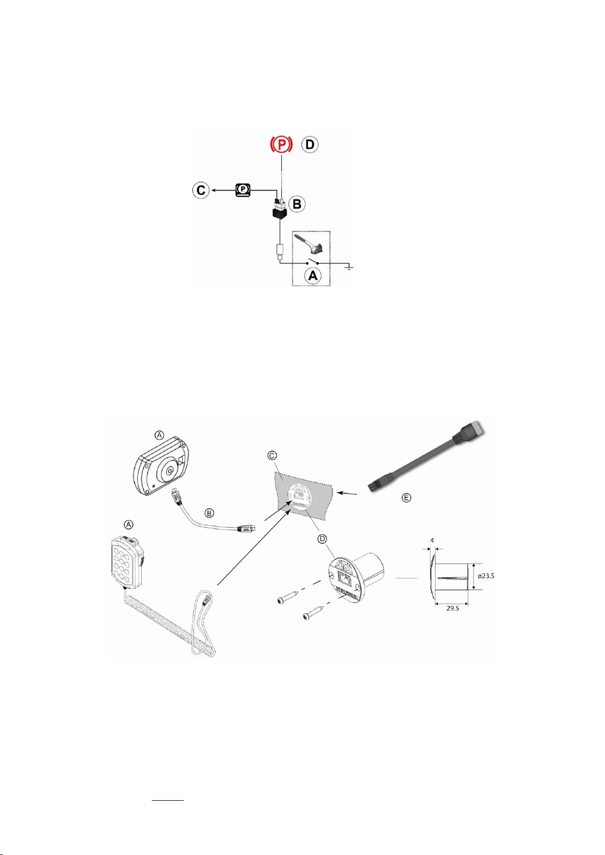
7.3. HANDBRAKE MODULE OPTION
The HANDBRAKE module is an option that enables obtaining the information on the handbrake
status from the ignition switch of the vehicle without disturbing the original circuit of the vehicle. It
must imperatively be inserted between the contactor of the vehicle and the information line
connecting it to the dashboard indicator circuit.
A. Vehicle’s HANDBRAKE contactor
B. MERCURA’s HANDBRAKE module
C. HAND BRAKE status information output to MERCURA system to be wired on wire n° 9 of the
vehicle’s harness of the VEGA lightbar with siren.
D. HANDBRAKE LED circuit of the vehicle dashboard
7.4. DASHBOARD INTERFACE OPTION
A. Control box or SPA Handy
B. 8-way Bus CAN CPT
C. Vehicle’s dashboard
D. Dashboard interface
E. BUS-wired adaptor
Table of contents
Other Mercura Automobile Accessories manuals


Popular Automobile Accessories manuals by other brands


Federal Signal Corporation
Federal Signal Corporation CUDA TRIOPTIC 351011 Series instruction sheet

ensto
ensto One Apartment Series quick guide

EUFAB
EUFAB CROW 1 operating instructions

Continental Refrigerator
Continental Refrigerator TIS-04 owner's manual

B-PWR
B-PWR PARB-144-146 Instruction guide

Rightline Gear
Rightline Gear Ace 2 Setup guide