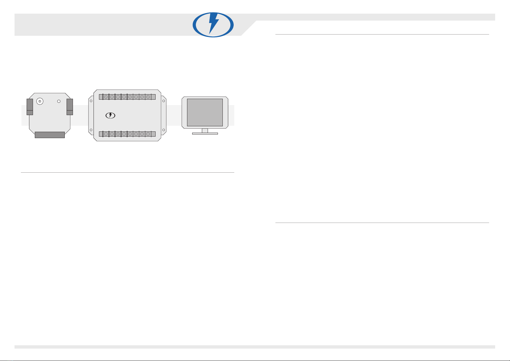
ELECTRIC VEHICLE MANAGEMENT SYSTEM V3 ZERO EMISSION VEHICLES AUSTRALIA
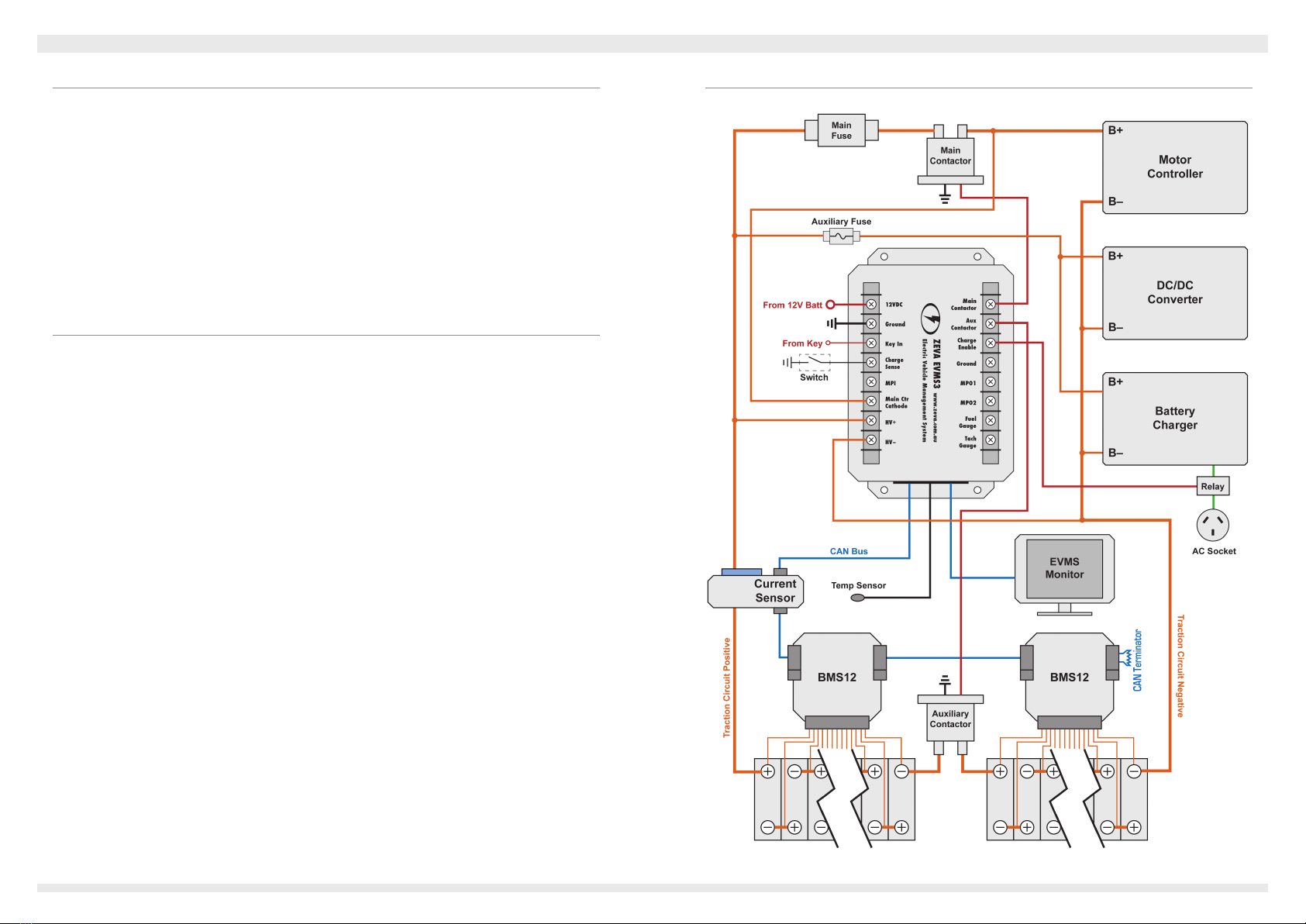
Current Sensor
TheEVMS3communicateswithacurrentsensorontheCANbustoreceiveinstantaneous
current,andusesthistocalculatebatteryStateofChargethroughintegrationovertime.Two
typesofcurrentsensorareavailable,HallEffectorShunt.
HallEffectcurrentsensorsareavailablefor300A,600Aor1200Amaximum,and•
areinstalledsimplybyslippingthebatterycablethroughthebluetorusofthehall
sensor.Smallerratedsensorsofferproportionallyhighermeasurementaccuracyso
aremoreappropriateforlowercurrentsystems.Hallsensorsarenormallyeasierto
installandgeneratenoheat,butarealittlemoreexpensiveandhaveslightlyless
accuratezeropoint.
TheShuntInterfacemeasurescurrentowthroughashuntinstalledonthebattery•
cableandoutputsittotheCANbus.TheShuntInterfacecanworkwith50A,100A,
200Aor500Ashunts,either75mVor50mV.Smallershuntsofferproportionately
highermeasurementresolution.Note that the current ratings for the shunts are
maximum continuous ratings, but the shunt interface can measure up to twice the
shunt’s nominal rating intermittently - limited by heat buildup in the shunt.Ashunt
interfaceplusshuntworksoutalittlecheaperthantheHallEffectsensorandhasa
slightlymoreaccuratezeropoint(betteraccuracywithverylowcurrents),butcan
bealittlemoreefforttoinstall,andgeneratessomeheat.
Asageneralguide,halleffectsensorsaremoresuitableforhighpowersystems,andshunts
aremoresuitableforlowerpowersystems.
Inbothcasesthecurrentsensororshuntmaybeinstalledoneitherthepositiveornegative
batterywire.TheHallSensorshouldbeorientedsuchthatdischargecurrentowsfromthe
back(black)sidetothefront(blue)side.Ensurethattherearenodevicesinstalledbetween
thebatteryandthecurrentsensororshunt,ortheEVMSwillnotbeabletocalculatestateof
chargecorrectly,sincethecurrentowto/fromthosedeviceswouldnotbemeasuredbythe
currentsensor.Note: If the status light is blinking when no current is owing, hold down the
button until it stops blinking to recalibrate the sensor’s zero point.
Charger Integration Options
Toenablecharging,theEVMSneedstoswitchintochargingmodebyconnectingtheCharge
Senseinputtoground/chassis.Thiswillwakeitfromsleepifneeded,poweruptheCAN
bustocommunicatewithBMSmodules,andstartthecharger.Itwillalsopreventthevehicle
frombeing accidentallydrivenoffwhileplugged into charge.Thereare severalwaysto
implementchargedetection:
Amagneticreedswitch(orsimilar)canbewiredbetweenChargeSenseand•
ground/chassis,andsetuptocloseitscontactswhenthedoor/covertothecharging
portisopened.
AnACrelaywithitscoilwiredinparallelwiththecharger’sACinput,sothatwhen-•
everthechargerhaspower,therelaywillalsoclosetoenableEVMSchargemode.
Somechargers(e.gnewerTCChargers)haveanoutput12Vsupplywhichcanbe•
usedtoswitchasmallsignalrelaytojoinChargeSensetoground/chassis.
ItisalsoessentialthattheEVMSisabletoswitchoffthechargerifanycellsexceedsafe
voltage,topreventdamagefromover-charging.Thereareseveralwaystoimplementthis:
IfusingCANintegrationwithaTCCharger,theEVMSisabletodisablethecharger•
overCANbussonoadditionalcontrolrelaysarerequired,andtheChargeEnable
outputcanbeleftunused.ToconnectaTCChargertoaZEVACANbus,join only
the CANGND, CANL and CANH pins.(Thechargeralsohasa12Vpinbutthis
shouldnotbejoinedtotheZEVACANbus,sinceitisa12Voutput,andonlythe
EVMSshouldmanage12VpowertotheCANbus.)
Manychargershaveapairofcontrolpinsthatgetjoinedtoenablethecharger.To•
usethismechanism,useasmall12VrelayswitchedbytheChargeEnableoutputof
theEVMS,withthenormallyopencontactswiredtotheenablepins.
TheAuxiliaryContactoroutputisdisabledaswellastheChargeEnableoutputif•
anycellsgoover-voltage,soifyourtractioncircuithasanyauxiliarycontactors
(andyourchargeristolerantofhavingitsDCsideinterruptedmid-charging),there
isnoneedtoaddfurtherrelays/contactorstostopthecharger,astheopeningofthe
auxiliarycontactorwillnecessarilyinterruptchargecurrent.
Thenaloption,whichcanbesafelyusedwithanycharger,istouseapowerrelay•
switchedbytheChargeEnableterminalfromtheEVMS,withtherelay’sNormally
OpenoutputswiredtointerrupttheACinputtothecharger(asshownontheex-
amplewiringdiagramonthepreviouspage).
Auxiliary Contactors
Auxiliarycontactors(asshownontheexamplecircuitdiagram)areoptionalbutcanserve
severalfunctionsinanEV.
Splituphighvoltagebatterypacksintosmallergroupsofnon-lethalvoltage,orto•
isolateseparategroupsofcellsdistributedaroundthevehicle,forsafety.
Switchon/offotherHVloadsthatarebeforethemaincontactor,eitherdirectly(us-•
ingarelayswitchingpowertothedeviceitself)orindirectly(bybreakingthemain
tractioncircuit).ThemostcommonexampleistheDC/DCconverter,sothatitisnot
permanentlyin-circuit.
Effectivelyfunctioningasanautomaticmaintenanceswitch.(Ifyoudon’thavean•
auxiliarycontactorbreakingthetractioncircuitwhenthekeyisoff,itisadvisable
tohaveamanualmaintenanceswitchtodothesamejobwheneverworkingonthe
vehicle.)
87